EP2009674A2 - Dispositif de fabrication et de présentation de couches de liquide - Google Patents
Dispositif de fabrication et de présentation de couches de liquide Download PDFInfo
- Publication number
- EP2009674A2 EP2009674A2 EP08104357A EP08104357A EP2009674A2 EP 2009674 A2 EP2009674 A2 EP 2009674A2 EP 08104357 A EP08104357 A EP 08104357A EP 08104357 A EP08104357 A EP 08104357A EP 2009674 A2 EP2009674 A2 EP 2009674A2
- Authority
- EP
- European Patent Office
- Prior art keywords
- liquid
- carrier plate
- liquid layer
- layer
- liquid carrier
- Prior art date
- Legal status (The legal status is an assumption and is not a legal conclusion. Google has not performed a legal analysis and makes no representation as to the accuracy of the status listed.)
- Granted
Links
Images


Classifications
-
- B—PERFORMING OPERATIONS; TRANSPORTING
- B23—MACHINE TOOLS; METAL-WORKING NOT OTHERWISE PROVIDED FOR
- B23K—SOLDERING OR UNSOLDERING; WELDING; CLADDING OR PLATING BY SOLDERING OR WELDING; CUTTING BY APPLYING HEAT LOCALLY, e.g. FLAME CUTTING; WORKING BY LASER BEAM
- B23K3/00—Tools, devices or special appurtenances for soldering, e.g. brazing, or unsoldering, not specially adapted for particular methods
- B23K3/08—Auxiliary devices therefor
- B23K3/082—Flux dispensers; Apparatus for applying flux
-
- B—PERFORMING OPERATIONS; TRANSPORTING
- B23—MACHINE TOOLS; METAL-WORKING NOT OTHERWISE PROVIDED FOR
- B23K—SOLDERING OR UNSOLDERING; WELDING; CLADDING OR PLATING BY SOLDERING OR WELDING; CUTTING BY APPLYING HEAT LOCALLY, e.g. FLAME CUTTING; WORKING BY LASER BEAM
- B23K1/00—Soldering, e.g. brazing, or unsoldering
- B23K1/20—Preliminary treatment of work or areas to be soldered, e.g. in respect of a galvanic coating
- B23K1/203—Fluxing, i.e. applying flux onto surfaces
-
- B—PERFORMING OPERATIONS; TRANSPORTING
- B23—MACHINE TOOLS; METAL-WORKING NOT OTHERWISE PROVIDED FOR
- B23K—SOLDERING OR UNSOLDERING; WELDING; CLADDING OR PLATING BY SOLDERING OR WELDING; CUTTING BY APPLYING HEAT LOCALLY, e.g. FLAME CUTTING; WORKING BY LASER BEAM
- B23K3/00—Tools, devices or special appurtenances for soldering, e.g. brazing, or unsoldering, not specially adapted for particular methods
- B23K3/06—Solder feeding devices; Solder melting pans
- B23K3/0607—Solder feeding devices
- B23K3/0638—Solder feeding devices for viscous material feeding, e.g. solder paste feeding
-
- H—ELECTRICITY
- H10—SEMICONDUCTOR DEVICES; ELECTRIC SOLID-STATE DEVICES NOT OTHERWISE PROVIDED FOR
- H10P—GENERIC PROCESSES OR APPARATUS FOR THE MANUFACTURE OR TREATMENT OF DEVICES COVERED BY CLASS H10
- H10P72/00—Handling or holding of wafers, substrates or devices during manufacture or treatment thereof
- H10P72/04—Apparatus for manufacture or treatment
- H10P72/0402—Apparatus for fluid treatment
- H10P72/0404—Apparatus for fluid treatment for general liquid treatment, e.g. etching followed by cleaning
-
- H—ELECTRICITY
- H10—SEMICONDUCTOR DEVICES; ELECTRIC SOLID-STATE DEVICES NOT OTHERWISE PROVIDED FOR
- H10P—GENERIC PROCESSES OR APPARATUS FOR THE MANUFACTURE OR TREATMENT OF DEVICES COVERED BY CLASS H10
- H10P72/00—Handling or holding of wafers, substrates or devices during manufacture or treatment thereof
- H10P72/04—Apparatus for manufacture or treatment
- H10P72/0448—Apparatus for applying a liquid, a resin, an ink or the like
-
- B—PERFORMING OPERATIONS; TRANSPORTING
- B23—MACHINE TOOLS; METAL-WORKING NOT OTHERWISE PROVIDED FOR
- B23K—SOLDERING OR UNSOLDERING; WELDING; CLADDING OR PLATING BY SOLDERING OR WELDING; CUTTING BY APPLYING HEAT LOCALLY, e.g. FLAME CUTTING; WORKING BY LASER BEAM
- B23K2101/00—Articles made by soldering, welding or cutting
- B23K2101/36—Electric or electronic devices
- B23K2101/40—Semiconductor devices
Definitions
- the present invention relates to a device for producing and presenting liquid layers, comprising a liquid carrier plate, a liquid container for applying a liquid layer on a surface of the liquid carrier plate, and a lifting mechanism by means of which the liquid carrier plate and the liquid container relative to each other are displaced or displaced.
- Such devices are for example from the patent US 6,293,317 B1 known.
- This patent discloses a downwardly open liquid container for receiving flux which is movable over a plate containing recesses for receiving the flux. Upon movement of the container over this plate, flux is discharged through the lower opening of the liquid container, and then the recesses in the plate are filled with the flux. Thereafter, for example, the contacts of semiconductor devices are immersed in such a filled recess and so wetted with flux, for example, for soldering to a circuit board.
- a device for producing and presenting liquid layers comprising a liquid carrier plate, a liquid container for applying a liquid layer on a surface of the liquid carrier plate, and a lifting mechanism by means of which the liquid carrier plate and the liquid container are displaceable or displaced relative to each other, wherein the device is furthermore designed and arranged such that that in an application position of the lifting mechanism, the liquid container for applying a liquid layer is movable or moved over the liquid carrier plate, and in a wetting position of the lifting mechanism, the liquid container lies in and / or below a surface plane of an applied liquid layer.
- the embodiment of the application and wetting position described above causes the liquid carrier plate to be raised in the wetting position relative to the liquid carrier plate in comparison to the application position. This reduces the spatial barrier formed by the liquid container when accessing the surface plane. Therefore, for example, in the Liquid layer to be immersed component for lifting over the liquid container less raised or lowered. This then, for example, a faster use of the liquid layer is possible or less mechanical effort to use the liquid layer necessary. Therefore, a device according to the above description improves the spatial accessibility to the liquid layer.
- the wetting position of the lifting mechanism can be configured such that the liquid container lies in the surface plane of an applied liquid layer, wherein the surface plane intersects the liquid container and, for example, 10 percent, 20 percent, 50 percent, 90 percent or even 100 percent of the filled from the liquid container Volume below the surface level lie.
- liquids for example, flux for soldering processes, solder pastes, adhesives, thermal pastes, electrical conductive pastes or any other liquids, especially liquids with high viscosity, be.
- the liquid carrier plate may comprise at least one planar area for applying liquids. It may, for example, also comprise a plurality of planar regions, in particular a plurality of separate planar regions. If the surface of the liquid carrier plate comprises a plurality of planar surface regions, in particular a plurality of separate planar surface regions, all these regions can have an identical vertical position or different elevations (for example for producing layers with different thicknesses in one operation).
- the liquid carrier plate may also have non-planar areas, such as grooves for discharging liquid residues.
- the liquid carrier plate may be a substantially flat plate with a circumferential groove in the edge region of the plate for the discharge of liquid residues.
- the liquid carrier plate may be formed as a substantially flat plate having at least one recess for receiving the liquids. In the latter case, the "bottom surface" of the at least one depression is then the surface of the liquid carrier plate for applying the liquid layer.
- the surface of the liquid carrier plate on which the liquid layer is applied or may be substantially planar.
- the displacement of the liquid carrier plate and the liquid container relative to one another can be effected such that at least one component of the displacement movement is perpendicular to the surface of the liquid carrier plate. Furthermore, the total displacement may be substantially perpendicular to the surface of the liquid carrier plate.
- the surface here is the area of the liquid carrier plate considered, on which the liquid layers can be applied or applied.
- an application position can correspond to a layer thickness of a liquid layer to be applied or applied.
- An application position is generally characterized by the fact that in the presence of an application position, the liquid container for moving a layer over the plate is movable or is moved.
- the liquid container can be moved, for example, parallel to the surface or along the surface of the liquid carrier plate. The movement can take place at least over parts of the liquid carrier plate.
- the liquid container can be moved substantially over the entire liquid carrier plate.
- the liquid container for applying a liquid layer can also be moved from a starting position over substantially the entire liquid carrier plate and then brought back into the starting position.
- the device can be provided that all areas of the liquid container lie in and / or below the surface level of an applied liquid layer. This means that no areas of the liquid container project beyond this surface level.
- the liquid container may still be in the surface plane with an upper side, while all remaining regions of the liquid container lie below the surface plane.
- the liquid container can also lie overall below the surface level of an applied liquid layer. This embodiment has the advantage that the liquid container no longer forms a barrier in the wetting position of the lifting mechanism for an element to be immersed in the liquid, via which the element would possibly have to be lifted. Therefore, this further improves the spatial accessibility to an applied liquid layer.
- all other regions of the device lie in and / or below the surface plane of an applied liquid layer.
- all regions of the device may also lie in and / or below the surface plane of an applied liquid layer.
- the device can also be designed such that a thickness of a liquid layer to be applied is adjustable or adjusted by means of the lifting mechanism.
- the thickness of the liquid layer to be applied for example, between a predetermined or predetermined minimum and a predetermined or predetermined maximum Thickness value continuously adjustable.
- Continuous adjustability of the thickness of a liquid layer to be applied between a minimum and maximum thickness value allows very flexible adaptation of the thickness of the liquid layer to e.g. Components that are immersed for example in this liquid layer and / or wetted with the liquid. As a result, the device is better adaptable to possible applications of the liquid layers.
- the thickness of a liquid layer to be applied may be predetermined, for example, by a height difference of the surface of the liquid carrier plate on which the liquid is applied and a lower edge of the liquid container. This is particularly applicable to devices in which the liquid containers have on their underside an opening from which the liquid emerges for application on the surface.
- An applied liquid layer may for example be partially or fully stabilized by its surface tension. Furthermore, an applied liquid layer can also be partially or completely stabilized by a mechanical boundary (eg a sidewall).
- the liquid carrier plate may be designed such that it does not have any side elements projecting vertically beyond the surface for applying the liquid layer for delimiting an applied or to be applied liquid layer.
- Such an applied liquid layer is thus e.g. not limited by walls and / or located in a depression but is at least partially stabilized, for example, on the surface tension of the liquid.
- This embodiment has the advantage that comparatively easily a continuous adjustability of a liquid layer to be applied can be achieved because, for example, no side or wall elements of a certain height can hinder the movement of the liquid container.
- the liquid carrier plate can also have one or more depressions for receiving a liquid layer.
- This embodiment has e.g. the advantage that the liquids are stored safely in the wells and the liquid layer is thereby stabilized
- the device may also comprise a base element, wherein the base element may be designed in particular for fastening the device to a carrier.
- a device may for example also be designed such that it is fastened or attachable by means of the base element to a base unit of a placement machine.
- the base element may be, for example, a completely or partially closed housing, a carrier unit or even a mechanical support frame or a skeleton.
- the lifting mechanism can be designed so that upon actuation of the lifting mechanism, the liquid carrier plate moves relative to the base member. Furthermore, the device can be configured such that upon actuation of the lifting mechanism, the liquid container moves relative to the base member.
- the lifting mechanism may be configured, for example, as a manually operated or actuatable lifting mechanism.
- the lifting mechanism may comprise a drive unit for moving the liquid carrier plate or the liquid container.
- the drive unit can be used, for example, as a motor, e.g. an electric motor, or be designed as a hydraulic or pneumatic drive unit.
- the drive unit may be, e.g. in the case of a motor, for example, be fixed relative to the base member.
- Such a designed lifting mechanism allows a simplified control of the device described.
- the lifting mechanism may comprise a first drive element driven by the drive unit and a second drive element located on the liquid carrier plate or the liquid container, wherein the first drive element cooperates with the second drive element for moving the liquid carrier plate or the liquid container.
- the first drive element can be configured as a wedge-shaped element at least in sections
- the second drive element can be configured as a wedge-shaped element which is also adapted thereto, at least in sections.
- Drive elements may for example include rollers, wheels, belts or the like. This configuration results in a mechanically simple and easy to produce construction.
- the lifting mechanism can be designed such that the first drive element for moving the liquid carrier plate or the liquid container is moved substantially parallel to the surface of the liquid carrier plate or is movable.
- the first and second drive elements may each have an angled to the surface of the liquid carrier plate oriented sliding surface, wherein the sliding surfaces of the drive elements are arranged and configured such that they move past each other during a movement of the liquid carrier plate by the drive unit.
- the sliding surfaces can be formed, for example, as a sliding bearing. Furthermore, rollers, guide rails and / or carriages can be provided on the sliding surfaces. Due to the aforementioned structure of the lifting mechanism, a space-saving drive with a simplified and easily producible structure can be achieved.
- a placement machine for equipping electrical and / or optical components on substrates comprising: a gripper for receiving electrical and / or optical components from a supply area of the placement machine and depositing the components on a substrate and a device for producing and presenting liquid layers according to the above description, wherein the placement machine is designed and arranged such that at least contact portions of held by the gripper electrical and / or optical components after receiving the components from the feed area and before settling on the substrate are at least partially wetted with the liquid or wetted using the device for the preparation and presentation of liquid layers.
- Such grippers for receiving electrical and / or optical components may be formed, for example, as suction pipettes or mechanical grippers.
- the wetting of the components with the liquid of the liquid layer can, for example, be such that a component held by the gripper is at least partially immersed in the liquid layer by movement of the gripper.
- a simplified spatial accessibility to a liquid layer in the device can be achieved with such a placement when setting the wetting position of the device. This can be done, for example, by raising in the wetting position the liquid layer relative to the liquid container and the application position and so e.g. the liquid container can form a smaller spatial barrier during transport of a component to the liquid layer.
- the placement machine can furthermore be designed such that the device for producing and presenting liquid layers at least partially in the feed area or is arranged adjacent to the feed area.
- the device can be fastened, for example, to the placement machine, for example to a base unit of the placement machine.
- the device can also be connected, for example, to a base unit of feed elements. In this way, the spatial accessibility to the liquid layers is further improved since components removed from the feed area only have to travel a relatively short distance if they are to be immersed in the liquid layer.
- the application position can be set such that a thickness of the liquid layer to be applied is predefined or can be predetermined by the distance between the lower edge of the liquid container and the surface of the liquid carrier plate.
- a liquid layer be produced with defined, eg, continuously adjustable, thickness.
- the thickness of the liquid layer to be applied depends on other parameters, such as the distance from the lower edge of the liquid container to the surface of the liquid carrier plate.
- the physico-chemical properties of the liquid e.g. Surface tension and toughness, and / or from the design of the liquid carrier plate.
- the liquid container may be moved over the liquid carrier plate, e.g. along or parallel to the surface of the liquid carrier plate.
- the liquid carrier plate can be moved under the liquid container. In this way, a liquid layer can be created on the liquid carrier plate in a simplified manner.
- the application position can be set such that the distance of the lower edge of the liquid container to the surface of the liquid carrier plate of a thickness of the liquid layer to be applied is predetermined or can be predetermined. Due to the viscosity of the liquid and the wetting of the liquid on the liquid carrier plate, the layer thickness of a prepared liquid layer may be smaller than the above-described distance between the lower edge of the liquid container to the surface of the liquid carrier plate.
- liquid container can also be moved through the liquid carrier plate or the liquid carrier plate under the liquid container to apply the liquid layer.
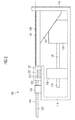
- FIG. 1 1 shows a device contact for dipping component contacts in flux with which a thin flux layer 144 has been formed on a liquid carrier plate 140.
- the device 100 comprises a liquid container 120 which stores a supply of liquid flux 124 in a downwardly open storage region 122.
- the liquid container 120 is movable by means of an electric drive 126 via a push rod 128 along the surface of the liquid carrier plate 140.
- the push rod can be formed, for example, as a threaded rod, in which case the drive unit 126 may include a corresponding threaded counter-element which is driven by a corresponding rotary drive.
- the liquid carrier plate 140 is designed to be height-adjustable, wherein the height adjustment via the interaction of attached to the liquid carrier plate 140 wedge-shaped lifting element 142 causes a provided with a corresponding slope thrust element 130.
- the thrust element 130 is via a drive unit 136 and a corresponding push rod 138 in FIG. 1 horizontally movable.
- the drive 136 and the push rod 138 may be formed, for example, corresponding to the drive 126 and the push rod 128 for the liquid container 120.
- the thrust element 130 in FIG. 1 can then, for example by means of the drive 136 via the push rod 138, the thrust element 130 in FIG. 1 to be moved to the right. Since the liquid carrier plate 140 and the lifting wedge 142 fixed thereto are movably supported in a vertical direction, said movement of the pushing element 130 will be moved by a movement of the contacting surfaces of the pushing element 130 and the lifting element 142 into a lifting movement of the lifting element 142 and thus connected liquid carrier plate 140 formed. In this way, vertical movement of the pusher 130 allows the liquid carrier plate 140 to move vertically up and down.
- a lifting mechanism comprises e.g. The push element 142, the push element 130 and the drive unit 136 and the push rod 138.
- the push element 130 would be a possible first drive element according to the above description and the lifting element 142 a possibility of a second drive element according to the above description.
- the device for immersing components in flux 100 comprises a support structure 110 to which both the drive unit 126 for the liquid container 120 and the drive unit 136 for the push element 130 are fixed.
- the liquid carrier plate 140 relative to the support structure 110 in the vertical direction movable.
- the liquid container 120 is movable relative to the support structure 110 in the horizontal direction.
- a distance of the surface of the liquid carrier plate 140 to a lower edge of the liquid container 120 is then adjusted by means of the pusher 130 via the drive unit 136 such that the layer thickness of the liquid layer 144 to be applied is predetermined by the distance.
- the liquid container 120 is guided horizontally by means of its drive unit 126 via the liquid carrier plate 140, wherein the flux 124 emerges from the lower opening of the storage area 122 of the storage container.
- the movement of the liquid container 120 over the liquid carrier plate 140 then forms the liquid layer 144 of flux. After retraction of the liquid container 120 in the in FIG. 1 As shown, the liquid layer 144 of flux is ready for use.
- liquid carrier plate 140 has no vertical boundaries for the flux layer 144, so that the flux layer 144 is stabilized solely by their surface tension.
- FIG. 1 For example, one possibility of an application position of the lifting mechanism 130, 136, 138, 142 is shown, wherein a surface plane 146 of the applied liquid layer 144 is just below the liquid container 120.
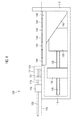
- FIG. 2 is the in FIG. 1 illustrated apparatus for producing flux layers 100 in a wetting position shown.
- the above with respect FIG. 1 described reference numerals correspond to those in FIG. 2 ,
- wetting position of the device 100 is about a movement of the thrust member 130 to the right and a resulting movement of the liquid carrier plate 140 raised it so that parts of the liquid container 120 below the surface plane 146 of the applied liquid layer 144.
- substantial parts, ie more than 50% of the volume filled in by the liquid container 120 lie below the surface plane 146.
- the liquid container 120 lies in the surface plane 146 of the liquid layer 144.
- FIG. 3 Another possibility is a wetting position in FIG. 1 and 2 illustrated device 100 for producing a flux layer 100 shown.
- the liquid carrier plate 140 is raised above the lifting mechanism 130, 136, 138, 142 so far, all regions of the liquid container 120 lie in or below the surface plane 146 of the applied flux layer 144. That is, no area of the liquid container 120 protrudes beyond the surface plane 146.
- This must be a component, which, for example, held by a gripper, from the left in FIG. 3 is brought to the flux layer 144, are not further lowered before the start of the immersion process in the flux layer 144. Therefore, by the in FIG. 3 shown wetting position further improves the spatial accessibility of the flux layer 144 for a component to be immersed.
- FIG. 4 shows a further embodiment for stabilizing the liquid layer 144 on the liquid carrier plate 140 in the FIGS. 1 to 3
- a plate 148 is provided with openings on the liquid carrier plate 140, so that after movement of the reservoir 120 for the flux 124 over the surface of the perforated plate 148 in the openings of the perforated plate 148, the liquid layer 144th was produced.
- the thickness of the liquid layer 144 is given substantially by the thickness of the perforated plate 148.
- FIG. 4 are in FIG. 4 not all elements of the perforated plate 148 and the liquid layer 144 provided with a corresponding reference numeral.
- the loss of flux can be reduced because during the application and later presentation of the liquid layer 144, liquid losses due to lateral flow of flux, in particular in the edge regions of the liquid layer 144, are severely limited or even avoided.
- the present invention describes an apparatus for the preparation and presentation of liquid layers, wherein a wettability position adjustable after the application of the liquid layer provides a simplified, better and faster accessibility of the produced liquid layer for e.g. an element to be used with the liquid layer is achieved.
Landscapes
- Engineering & Computer Science (AREA)
- Mechanical Engineering (AREA)
- Coating Apparatus (AREA)
- Materials For Medical Uses (AREA)
- Encapsulation Of And Coatings For Semiconductor Or Solid State Devices (AREA)
Applications Claiming Priority (1)
| Application Number | Priority Date | Filing Date | Title |
|---|---|---|---|
| DE102007029726A DE102007029726A1 (de) | 2007-06-27 | 2007-06-27 | Vorrichtung zur Herstellung und Präsentation von Flüssigkeitsschichten |
Publications (4)
| Publication Number | Publication Date |
|---|---|
| EP2009674A2 true EP2009674A2 (fr) | 2008-12-31 |
| EP2009674A3 EP2009674A3 (fr) | 2010-06-30 |
| EP2009674B1 EP2009674B1 (fr) | 2011-04-13 |
| EP2009674B8 EP2009674B8 (fr) | 2011-09-21 |
Family
ID=39682764
Family Applications (1)
| Application Number | Title | Priority Date | Filing Date |
|---|---|---|---|
| EP08104357A Not-in-force EP2009674B8 (fr) | 2007-06-27 | 2008-06-11 | Dispositif de fabrication et de présentation de couches de liquide |
Country Status (4)
| Country | Link |
|---|---|
| EP (1) | EP2009674B8 (fr) |
| CN (1) | CN101332454B (fr) |
| AT (1) | ATE505812T1 (fr) |
| DE (2) | DE102007029726A1 (fr) |
Cited By (4)
| Publication number | Priority date | Publication date | Assignee | Title |
|---|---|---|---|---|
| EP2009673A3 (fr) * | 2007-06-27 | 2010-06-30 | Siemens Electronics Assembly Systems GmbH & Co. KG | Dispositif de fabrication de couches de liquides dotées d'épaisseurs prédéfinies sur un support |
| CN103521400A (zh) * | 2013-10-24 | 2014-01-22 | 福建农林大学 | 一种激光熔敷试样预置涂层用夹具 |
| CN111158218A (zh) * | 2020-01-03 | 2020-05-15 | Tcl华星光电技术有限公司 | 曝光平台装置及曝光系统 |
| CN114340206A (zh) * | 2016-10-07 | 2022-04-12 | 先进装配系统有限责任两合公司 | 具有可变空穴深度的dip板及浸润电子元件接触接口的方法 |
Families Citing this family (1)
| Publication number | Priority date | Publication date | Assignee | Title |
|---|---|---|---|---|
| CN103861772B (zh) * | 2014-03-12 | 2017-01-25 | 王元 | 一种涂胶方法及装置 |
Citations (1)
| Publication number | Priority date | Publication date | Assignee | Title |
|---|---|---|---|---|
| US6293317B1 (en) | 1999-04-12 | 2001-09-25 | Esec Trading Sa | Method and device for the application of a liquid substance |
Family Cites Families (4)
| Publication number | Priority date | Publication date | Assignee | Title |
|---|---|---|---|---|
| US4946708A (en) * | 1988-11-18 | 1990-08-07 | International Business Machines Corporation | Pin transfer adhesive application for surface mount component processes |
| AT407325B (de) * | 1999-11-08 | 2001-02-26 | Datacon Semiconductor Equip | Einrichtung zum benetzen der oberfläche |
| JP2006231201A (ja) * | 2005-02-24 | 2006-09-07 | Tokyo Ohka Kogyo Co Ltd | 塗布装置 |
| DE102007029725A1 (de) * | 2007-06-27 | 2009-01-08 | Siemens Ag | Vorrichtung zur Herstellung von Flüssigkeitsschichten mit vorbestimmter Dicke auf einem Träger |
-
2007
- 2007-06-27 DE DE102007029726A patent/DE102007029726A1/de not_active Ceased
-
2008
- 2008-06-11 AT AT08104357T patent/ATE505812T1/de active
- 2008-06-11 DE DE502008003152T patent/DE502008003152D1/de active Active
- 2008-06-11 EP EP08104357A patent/EP2009674B8/fr not_active Not-in-force
- 2008-06-27 CN CN2008101275773A patent/CN101332454B/zh not_active Expired - Fee Related
Patent Citations (1)
| Publication number | Priority date | Publication date | Assignee | Title |
|---|---|---|---|---|
| US6293317B1 (en) | 1999-04-12 | 2001-09-25 | Esec Trading Sa | Method and device for the application of a liquid substance |
Cited By (4)
| Publication number | Priority date | Publication date | Assignee | Title |
|---|---|---|---|---|
| EP2009673A3 (fr) * | 2007-06-27 | 2010-06-30 | Siemens Electronics Assembly Systems GmbH & Co. KG | Dispositif de fabrication de couches de liquides dotées d'épaisseurs prédéfinies sur un support |
| CN103521400A (zh) * | 2013-10-24 | 2014-01-22 | 福建农林大学 | 一种激光熔敷试样预置涂层用夹具 |
| CN114340206A (zh) * | 2016-10-07 | 2022-04-12 | 先进装配系统有限责任两合公司 | 具有可变空穴深度的dip板及浸润电子元件接触接口的方法 |
| CN111158218A (zh) * | 2020-01-03 | 2020-05-15 | Tcl华星光电技术有限公司 | 曝光平台装置及曝光系统 |
Also Published As
| Publication number | Publication date |
|---|---|
| DE102007029726A1 (de) | 2009-01-02 |
| CN101332454B (zh) | 2013-01-30 |
| EP2009674B1 (fr) | 2011-04-13 |
| EP2009674A3 (fr) | 2010-06-30 |
| CN101332454A (zh) | 2008-12-31 |
| DE502008003152D1 (de) | 2011-05-26 |
| ATE505812T1 (de) | 2011-04-15 |
| EP2009674B8 (fr) | 2011-09-21 |
Similar Documents
| Publication | Publication Date | Title |
|---|---|---|
| DE4400523C2 (de) | Verfahren und Vorrichtung zum Herstellen eines dreidimensionalen Objekts | |
| EP3697597A1 (fr) | Dispositif de levage pour un cylindre de construction dans une machine, machine pour la fabrication de composants tridimensionnels comprenant un dispositif de levage ainsi que procédé pour la commande du dispositif de levage | |
| EP2009674B1 (fr) | Dispositif de fabrication et de présentation de couches de liquide | |
| EP3277481B1 (fr) | Procédé et dispositif de fabrication additive d'un corps | |
| EP0336232A1 (fr) | Procédé et dispositif pour le soudage par trempage de plaques conductrices | |
| DE10111033B4 (de) | Siebdruckverfahren | |
| DE102016004592B4 (de) | System und Verfahren zum Ausrichten elektronischer Bauteile | |
| WO2015091941A1 (fr) | Dispositif de fabrication d'un objet tridimensionnel par fixage magnétique de la base de construction | |
| DE68925520T2 (de) | Apparat zum Aufbringen von geringen Flüssigkeitsmengen | |
| DE102014213888A1 (de) | Justiervorrichtung und Justierverfahren | |
| EP2067166A1 (fr) | Procédé et dispositif d'aspersion des bosses d'une puce semi-conductrice avec un flux de brasage | |
| DE4210630A1 (de) | Elektrodenherstellungsgeraet | |
| DE4106733A1 (de) | Vorrichtung zum abblenden von feldlinien in einer galvanikanlage (iii) | |
| EP2009673B1 (fr) | Dispositif de fabrication de couches de liquides dotées d'épaisseurs prédéfinies sur un support | |
| DE9400364U1 (de) | Vorrichtung zum Herstellen eines dreidimensionalen Objekts | |
| DE4209385C2 (de) | Preßmaschine für elektronische Komponenten des Chip-Types | |
| DE2556928B2 (de) | Verfahren und Vorrichtung zum Züchten einer epitaktischen Halbleiterschicht in flüssiger Phase | |
| DE102008047114B4 (de) | Vorrichtung und Verfahren zum Hub-Tauch-Löten | |
| DE102016219558B4 (de) | DIP-Platte mit variabler Kavitätstiefe und Verfahren zum Dippen von Kontaktanschlüssen elektronischer Bauelemente | |
| DE102004050429B3 (de) | Vorrichtung zum definierten Aufbringen von Lotpulver auf ein Bauteil, deren Verwendung und ein dazugehöriges Verfahren | |
| DE3315794C2 (de) | Vorrichtung zur Flüssigphasenepitaxie | |
| AT407104B (de) | Einrichtung zum benetzen der oberfläche | |
| DE9400372U1 (de) | Vorrichtung zum Herstellen eines dreidimensionalen Objekts | |
| DE3123241C2 (de) | Verfahren zum Herstellen eines plattenförmigen Schaltmoduls | |
| EP0742425B1 (fr) | Dispositif pour appliquer sur des surfaces des quantités exactement dosées d'un matériau visqueux |
Legal Events
| Date | Code | Title | Description |
|---|---|---|---|
| PUAI | Public reference made under article 153(3) epc to a published international application that has entered the european phase |
Free format text: ORIGINAL CODE: 0009012 |
|
| AK | Designated contracting states |
Kind code of ref document: A2 Designated state(s): AT BE BG CH CY CZ DE DK EE ES FI FR GB GR HR HU IE IS IT LI LT LU LV MC MT NL NO PL PT RO SE SI SK TR |
|
| AX | Request for extension of the european patent |
Extension state: AL BA MK RS |
|
| RAP1 | Party data changed (applicant data changed or rights of an application transferred) |
Owner name: SIEMENS ELECTRONICS ASSEMBLY SYSTEMS GMBH & CO. KG |
|
| PUAL | Search report despatched |
Free format text: ORIGINAL CODE: 0009013 |
|
| AK | Designated contracting states |
Kind code of ref document: A3 Designated state(s): AT BE BG CH CY CZ DE DK EE ES FI FR GB GR HR HU IE IS IT LI LT LU LV MC MT NL NO PL PT RO SE SI SK TR |
|
| AX | Request for extension of the european patent |
Extension state: AL BA MK RS |
|
| RIC1 | Information provided on ipc code assigned before grant |
Ipc: H01L 21/00 20060101AFI20080818BHEP Ipc: B23K 1/20 20060101ALI20100525BHEP Ipc: B23K 3/08 20060101ALI20100525BHEP Ipc: B23K 3/06 20060101ALI20100525BHEP |
|
| 17P | Request for examination filed |
Effective date: 20100809 |
|
| RIC1 | Information provided on ipc code assigned before grant |
Ipc: B23K 1/20 20060101ALI20100827BHEP Ipc: B23K 3/08 20060101ALI20100827BHEP Ipc: H01L 21/00 20060101AFI20100827BHEP Ipc: B23K 3/06 20060101ALI20100827BHEP |
|
| GRAP | Despatch of communication of intention to grant a patent |
Free format text: ORIGINAL CODE: EPIDOSNIGR1 |
|
| GRAJ | Information related to disapproval of communication of intention to grant by the applicant or resumption of examination proceedings by the epo deleted |
Free format text: ORIGINAL CODE: EPIDOSDIGR1 |
|
| GRAP | Despatch of communication of intention to grant a patent |
Free format text: ORIGINAL CODE: EPIDOSNIGR1 |
|
| GRAS | Grant fee paid |
Free format text: ORIGINAL CODE: EPIDOSNIGR3 |
|
| AKX | Designation fees paid |
Designated state(s): AT BE BG CH CY CZ DE DK EE ES FI FR GB GR HR HU IE IS IT LI LT LU LV MC MT NL NO PL PT RO SE SI SK TR |
|
| GRAA | (expected) grant |
Free format text: ORIGINAL CODE: 0009210 |
|
| AK | Designated contracting states |
Kind code of ref document: B1 Designated state(s): AT BE BG CH CY CZ DE DK EE ES FI FR GB GR HR HU IE IS IT LI LT LU LV MC MT NL NO PL PT RO SE SI SK TR |
|
| REG | Reference to a national code |
Ref country code: GB Ref legal event code: FG4D Free format text: NOT ENGLISH |
|
| REG | Reference to a national code |
Ref country code: CH Ref legal event code: EP |
|
| REG | Reference to a national code |
Ref country code: IE Ref legal event code: FG4D Free format text: LANGUAGE OF EP DOCUMENT: GERMAN |
|
| REF | Corresponds to: |
Ref document number: 502008003152 Country of ref document: DE Date of ref document: 20110526 Kind code of ref document: P |
|
| REG | Reference to a national code |
Ref country code: DE Ref legal event code: R096 Ref document number: 502008003152 Country of ref document: DE Effective date: 20110526 |
|
| RAP2 | Party data changed (patent owner data changed or rights of a patent transferred) |
Owner name: ASM ASSEMBLY SYSTEMS GMBH & CO. KG |
|
| REG | Reference to a national code |
Ref country code: NL Ref legal event code: VDEP Effective date: 20110413 |
|
| LTIE | Lt: invalidation of european patent or patent extension |
Effective date: 20110413 |
|
| PG25 | Lapsed in a contracting state [announced via postgrant information from national office to epo] |
Ref country code: LT Free format text: LAPSE BECAUSE OF FAILURE TO SUBMIT A TRANSLATION OF THE DESCRIPTION OR TO PAY THE FEE WITHIN THE PRESCRIBED TIME-LIMIT Effective date: 20110413 Ref country code: PT Free format text: LAPSE BECAUSE OF FAILURE TO SUBMIT A TRANSLATION OF THE DESCRIPTION OR TO PAY THE FEE WITHIN THE PRESCRIBED TIME-LIMIT Effective date: 20110816 Ref country code: NO Free format text: LAPSE BECAUSE OF FAILURE TO SUBMIT A TRANSLATION OF THE DESCRIPTION OR TO PAY THE FEE WITHIN THE PRESCRIBED TIME-LIMIT Effective date: 20110713 Ref country code: HR Free format text: LAPSE BECAUSE OF FAILURE TO SUBMIT A TRANSLATION OF THE DESCRIPTION OR TO PAY THE FEE WITHIN THE PRESCRIBED TIME-LIMIT Effective date: 20110413 Ref country code: SE Free format text: LAPSE BECAUSE OF FAILURE TO SUBMIT A TRANSLATION OF THE DESCRIPTION OR TO PAY THE FEE WITHIN THE PRESCRIBED TIME-LIMIT Effective date: 20110413 |
|
| REG | Reference to a national code |
Ref country code: IE Ref legal event code: FD4D |
|
| PG25 | Lapsed in a contracting state [announced via postgrant information from national office to epo] |
Ref country code: CY Free format text: LAPSE BECAUSE OF FAILURE TO SUBMIT A TRANSLATION OF THE DESCRIPTION OR TO PAY THE FEE WITHIN THE PRESCRIBED TIME-LIMIT Effective date: 20110413 Ref country code: IS Free format text: LAPSE BECAUSE OF FAILURE TO SUBMIT A TRANSLATION OF THE DESCRIPTION OR TO PAY THE FEE WITHIN THE PRESCRIBED TIME-LIMIT Effective date: 20110813 Ref country code: GR Free format text: LAPSE BECAUSE OF FAILURE TO SUBMIT A TRANSLATION OF THE DESCRIPTION OR TO PAY THE FEE WITHIN THE PRESCRIBED TIME-LIMIT Effective date: 20110714 Ref country code: LV Free format text: LAPSE BECAUSE OF FAILURE TO SUBMIT A TRANSLATION OF THE DESCRIPTION OR TO PAY THE FEE WITHIN THE PRESCRIBED TIME-LIMIT Effective date: 20110413 Ref country code: SI Free format text: LAPSE BECAUSE OF FAILURE TO SUBMIT A TRANSLATION OF THE DESCRIPTION OR TO PAY THE FEE WITHIN THE PRESCRIBED TIME-LIMIT Effective date: 20110413 Ref country code: FI Free format text: LAPSE BECAUSE OF FAILURE TO SUBMIT A TRANSLATION OF THE DESCRIPTION OR TO PAY THE FEE WITHIN THE PRESCRIBED TIME-LIMIT Effective date: 20110413 Ref country code: ES Free format text: LAPSE BECAUSE OF FAILURE TO SUBMIT A TRANSLATION OF THE DESCRIPTION OR TO PAY THE FEE WITHIN THE PRESCRIBED TIME-LIMIT Effective date: 20110724 |
|
| PG25 | Lapsed in a contracting state [announced via postgrant information from national office to epo] |
Ref country code: MT Free format text: LAPSE BECAUSE OF FAILURE TO SUBMIT A TRANSLATION OF THE DESCRIPTION OR TO PAY THE FEE WITHIN THE PRESCRIBED TIME-LIMIT Effective date: 20110413 Ref country code: NL Free format text: LAPSE BECAUSE OF FAILURE TO SUBMIT A TRANSLATION OF THE DESCRIPTION OR TO PAY THE FEE WITHIN THE PRESCRIBED TIME-LIMIT Effective date: 20110413 |
|
| BERE | Be: lapsed |
Owner name: ASM ASSEMBLY SYSTEMS G.M.B.H. & CO. KG Effective date: 20110630 |
|
| PG25 | Lapsed in a contracting state [announced via postgrant information from national office to epo] |
Ref country code: CZ Free format text: LAPSE BECAUSE OF FAILURE TO SUBMIT A TRANSLATION OF THE DESCRIPTION OR TO PAY THE FEE WITHIN THE PRESCRIBED TIME-LIMIT Effective date: 20110413 Ref country code: IE Free format text: LAPSE BECAUSE OF FAILURE TO SUBMIT A TRANSLATION OF THE DESCRIPTION OR TO PAY THE FEE WITHIN THE PRESCRIBED TIME-LIMIT Effective date: 20110413 Ref country code: EE Free format text: LAPSE BECAUSE OF FAILURE TO SUBMIT A TRANSLATION OF THE DESCRIPTION OR TO PAY THE FEE WITHIN THE PRESCRIBED TIME-LIMIT Effective date: 20110413 |
|
| PLBE | No opposition filed within time limit |
Free format text: ORIGINAL CODE: 0009261 |
|
| STAA | Information on the status of an ep patent application or granted ep patent |
Free format text: STATUS: NO OPPOSITION FILED WITHIN TIME LIMIT |
|
| PG25 | Lapsed in a contracting state [announced via postgrant information from national office to epo] |
Ref country code: DK Free format text: LAPSE BECAUSE OF FAILURE TO SUBMIT A TRANSLATION OF THE DESCRIPTION OR TO PAY THE FEE WITHIN THE PRESCRIBED TIME-LIMIT Effective date: 20110413 Ref country code: RO Free format text: LAPSE BECAUSE OF FAILURE TO SUBMIT A TRANSLATION OF THE DESCRIPTION OR TO PAY THE FEE WITHIN THE PRESCRIBED TIME-LIMIT Effective date: 20110413 Ref country code: PL Free format text: LAPSE BECAUSE OF FAILURE TO SUBMIT A TRANSLATION OF THE DESCRIPTION OR TO PAY THE FEE WITHIN THE PRESCRIBED TIME-LIMIT Effective date: 20110413 Ref country code: SK Free format text: LAPSE BECAUSE OF FAILURE TO SUBMIT A TRANSLATION OF THE DESCRIPTION OR TO PAY THE FEE WITHIN THE PRESCRIBED TIME-LIMIT Effective date: 20110413 |
|
| 26N | No opposition filed |
Effective date: 20120116 |
|
| REG | Reference to a national code |
Ref country code: FR Ref legal event code: ST Effective date: 20120229 |
|
| PG25 | Lapsed in a contracting state [announced via postgrant information from national office to epo] |
Ref country code: BE Free format text: LAPSE BECAUSE OF NON-PAYMENT OF DUE FEES Effective date: 20110630 |
|
| PG25 | Lapsed in a contracting state [announced via postgrant information from national office to epo] |
Ref country code: FR Free format text: LAPSE BECAUSE OF NON-PAYMENT OF DUE FEES Effective date: 20110630 |
|
| REG | Reference to a national code |
Ref country code: DE Ref legal event code: R097 Ref document number: 502008003152 Country of ref document: DE Effective date: 20120116 |
|
| PG25 | Lapsed in a contracting state [announced via postgrant information from national office to epo] |
Ref country code: IT Free format text: LAPSE BECAUSE OF FAILURE TO SUBMIT A TRANSLATION OF THE DESCRIPTION OR TO PAY THE FEE WITHIN THE PRESCRIBED TIME-LIMIT Effective date: 20110413 |
|
| REG | Reference to a national code |
Ref country code: CH Ref legal event code: PL |
|
| REG | Reference to a national code |
Ref country code: CH Ref legal event code: PL |
|
| GBPC | Gb: european patent ceased through non-payment of renewal fee |
Effective date: 20120611 |
|
| PG25 | Lapsed in a contracting state [announced via postgrant information from national office to epo] |
Ref country code: LI Free format text: LAPSE BECAUSE OF NON-PAYMENT OF DUE FEES Effective date: 20120630 Ref country code: GB Free format text: LAPSE BECAUSE OF NON-PAYMENT OF DUE FEES Effective date: 20120611 Ref country code: MC Free format text: LAPSE BECAUSE OF NON-PAYMENT OF DUE FEES Effective date: 20110630 Ref country code: CH Free format text: LAPSE BECAUSE OF NON-PAYMENT OF DUE FEES Effective date: 20120630 |
|
| PG25 | Lapsed in a contracting state [announced via postgrant information from national office to epo] |
Ref country code: LU Free format text: LAPSE BECAUSE OF NON-PAYMENT OF DUE FEES Effective date: 20110611 |
|
| PG25 | Lapsed in a contracting state [announced via postgrant information from national office to epo] |
Ref country code: BG Free format text: LAPSE BECAUSE OF FAILURE TO SUBMIT A TRANSLATION OF THE DESCRIPTION OR TO PAY THE FEE WITHIN THE PRESCRIBED TIME-LIMIT Effective date: 20110713 |
|
| PG25 | Lapsed in a contracting state [announced via postgrant information from national office to epo] |
Ref country code: TR Free format text: LAPSE BECAUSE OF FAILURE TO SUBMIT A TRANSLATION OF THE DESCRIPTION OR TO PAY THE FEE WITHIN THE PRESCRIBED TIME-LIMIT Effective date: 20110413 |
|
| PG25 | Lapsed in a contracting state [announced via postgrant information from national office to epo] |
Ref country code: HU Free format text: LAPSE BECAUSE OF FAILURE TO SUBMIT A TRANSLATION OF THE DESCRIPTION OR TO PAY THE FEE WITHIN THE PRESCRIBED TIME-LIMIT Effective date: 20110413 |
|
| REG | Reference to a national code |
Ref country code: DE Ref legal event code: R081 Ref document number: 502008003152 Country of ref document: DE Owner name: ASMPT GMBH & CO. KG, DE Free format text: FORMER OWNER: ASM ASSEMBLY SYSTEMS GMBH & CO. KG, 81379 MUENCHEN, DE |
|
| P01 | Opt-out of the competence of the unified patent court (upc) registered |
Effective date: 20230530 |
|
| REG | Reference to a national code |
Ref country code: AT Ref legal event code: HC Ref document number: 505812 Country of ref document: AT Kind code of ref document: T Owner name: ASMPT GMBH & CO. KG, DE Effective date: 20230829 |
|
| PGFP | Annual fee paid to national office [announced via postgrant information from national office to epo] |
Ref country code: DE Payment date: 20240619 Year of fee payment: 17 |
|
| PGFP | Annual fee paid to national office [announced via postgrant information from national office to epo] |
Ref country code: AT Payment date: 20240620 Year of fee payment: 17 |
|
| REG | Reference to a national code |
Ref country code: DE Ref legal event code: R079 Ref document number: 502008003152 Country of ref document: DE Free format text: PREVIOUS MAIN CLASS: H01L0021000000 Ipc: H10P0095000000 |
|
| REG | Reference to a national code |
Ref country code: DE Ref legal event code: R119 Ref document number: 502008003152 Country of ref document: DE |
|
| REG | Reference to a national code |
Ref country code: AT Ref legal event code: MM01 Ref document number: 505812 Country of ref document: AT Kind code of ref document: T Effective date: 20250611 |
|
| PG25 | Lapsed in a contracting state [announced via postgrant information from national office to epo] |
Ref country code: DE Free format text: LAPSE BECAUSE OF NON-PAYMENT OF DUE FEES Effective date: 20260101 |
|
| PG25 | Lapsed in a contracting state [announced via postgrant information from national office to epo] |
Ref country code: AT Free format text: LAPSE BECAUSE OF NON-PAYMENT OF DUE FEES Effective date: 20250611 |