EP2009708A2 - Light emitting apparatus - Google Patents
Light emitting apparatus Download PDFInfo
- Publication number
- EP2009708A2 EP2009708A2 EP20080166586 EP08166586A EP2009708A2 EP 2009708 A2 EP2009708 A2 EP 2009708A2 EP 20080166586 EP20080166586 EP 20080166586 EP 08166586 A EP08166586 A EP 08166586A EP 2009708 A2 EP2009708 A2 EP 2009708A2
- Authority
- EP
- European Patent Office
- Prior art keywords
- wavelength conversion
- light emitting
- hole
- fixed
- conversion member
- Prior art date
- Legal status (The legal status is an assumption and is not a legal conclusion. Google has not performed a legal analysis and makes no representation as to the accuracy of the status listed.)
- Granted
Links
- 238000006243 chemical reaction Methods 0.000 claims abstract description 85
- 230000003287 optical effect Effects 0.000 claims abstract description 28
- 239000011521 glass Substances 0.000 claims description 24
- 238000002844 melting Methods 0.000 claims description 13
- 230000008018 melting Effects 0.000 claims description 13
- 239000000463 material Substances 0.000 claims description 10
- 239000005368 silicate glass Substances 0.000 claims description 5
- 238000000034 method Methods 0.000 description 8
- 239000004065 semiconductor Substances 0.000 description 5
- XLOMVQKBTHCTTD-UHFFFAOYSA-N Zinc monoxide Chemical compound [Zn]=O XLOMVQKBTHCTTD-UHFFFAOYSA-N 0.000 description 4
- 230000002238 attenuated effect Effects 0.000 description 4
- 239000003795 chemical substances by application Substances 0.000 description 4
- 230000031700 light absorption Effects 0.000 description 4
- 238000003466 welding Methods 0.000 description 4
- 239000000853 adhesive Substances 0.000 description 3
- 230000001070 adhesive effect Effects 0.000 description 3
- 230000015556 catabolic process Effects 0.000 description 3
- 238000006731 degradation reaction Methods 0.000 description 3
- 238000010438 heat treatment Methods 0.000 description 3
- 239000013307 optical fiber Substances 0.000 description 3
- 239000011347 resin Substances 0.000 description 3
- 229920005989 resin Polymers 0.000 description 3
- 229910000272 alkali metal oxide Inorganic materials 0.000 description 2
- 229910000287 alkaline earth metal oxide Inorganic materials 0.000 description 2
- 229910052810 boron oxide Inorganic materials 0.000 description 2
- 230000000052 comparative effect Effects 0.000 description 2
- JKWMSGQKBLHBQQ-UHFFFAOYSA-N diboron trioxide Chemical compound O=BOB=O JKWMSGQKBLHBQQ-UHFFFAOYSA-N 0.000 description 2
- 229910001392 phosphorus oxide Inorganic materials 0.000 description 2
- 239000000843 powder Substances 0.000 description 2
- VSAISIQCTGDGPU-UHFFFAOYSA-N tetraphosphorus hexaoxide Chemical compound O1P(O2)OP3OP1OP2O3 VSAISIQCTGDGPU-UHFFFAOYSA-N 0.000 description 2
- 239000011787 zinc oxide Substances 0.000 description 2
- 238000005219 brazing Methods 0.000 description 1
- 238000005260 corrosion Methods 0.000 description 1
- 230000000694 effects Effects 0.000 description 1
- 239000012535 impurity Substances 0.000 description 1
- 239000011812 mixed powder Substances 0.000 description 1
- 238000000465 moulding Methods 0.000 description 1
- 238000007789 sealing Methods 0.000 description 1
- 239000000126 substance Substances 0.000 description 1
Images



Classifications
-
- G—PHYSICS
- G02—OPTICS
- G02F—OPTICAL DEVICES OR ARRANGEMENTS FOR THE CONTROL OF LIGHT BY MODIFICATION OF THE OPTICAL PROPERTIES OF THE MEDIA OF THE ELEMENTS INVOLVED THEREIN; NON-LINEAR OPTICS; FREQUENCY-CHANGING OF LIGHT; OPTICAL LOGIC ELEMENTS; OPTICAL ANALOGUE/DIGITAL CONVERTERS
- G02F1/00—Devices or arrangements for the control of the intensity, colour, phase, polarisation or direction of light arriving from an independent light source, e.g. switching, gating or modulating; Non-linear optics
- G02F1/35—Non-linear optics
- G02F1/37—Non-linear optics for second-harmonic generation
-
- G—PHYSICS
- G02—OPTICS
- G02B—OPTICAL ELEMENTS, SYSTEMS OR APPARATUS
- G02B6/00—Light guides; Structural details of arrangements comprising light guides and other optical elements, e.g. couplings
- G02B6/24—Coupling light guides
- G02B6/42—Coupling light guides with opto-electronic elements
- G02B6/4201—Packages, e.g. shape, construction, internal or external details
- G02B6/4202—Packages, e.g. shape, construction, internal or external details for coupling an active element with fibres without intermediate optical elements, e.g. fibres with plane ends, fibres with shaped ends, bundles
-
- H—ELECTRICITY
- H01—ELECTRIC ELEMENTS
- H01S—DEVICES USING THE PROCESS OF LIGHT AMPLIFICATION BY STIMULATED EMISSION OF RADIATION [LASER] TO AMPLIFY OR GENERATE LIGHT; DEVICES USING STIMULATED EMISSION OF ELECTROMAGNETIC RADIATION IN WAVE RANGES OTHER THAN OPTICAL
- H01S3/00—Lasers, i.e. devices using stimulated emission of electromagnetic radiation in the infrared, visible or ultraviolet wave range
- H01S3/10—Controlling the intensity, frequency, phase, polarisation or direction of the emitted radiation, e.g. switching, gating, modulating or demodulating
- H01S3/106—Controlling the intensity, frequency, phase, polarisation or direction of the emitted radiation, e.g. switching, gating, modulating or demodulating by controlling devices placed within the cavity
- H01S3/108—Controlling the intensity, frequency, phase, polarisation or direction of the emitted radiation, e.g. switching, gating, modulating or demodulating by controlling devices placed within the cavity using non-linear optical devices, e.g. exhibiting Brillouin or Raman scattering
- H01S3/109—Frequency multiplication, e.g. harmonic generation
-
- H—ELECTRICITY
- H10—SEMICONDUCTOR DEVICES; ELECTRIC SOLID-STATE DEVICES NOT OTHERWISE PROVIDED FOR
- H10H—INORGANIC LIGHT-EMITTING SEMICONDUCTOR DEVICES HAVING POTENTIAL BARRIERS
- H10H20/00—Individual inorganic light-emitting semiconductor devices having potential barriers, e.g. light-emitting diodes [LED]
- H10H20/80—Constructional details
- H10H20/85—Packages
- H10H20/8506—Containers
-
- H—ELECTRICITY
- H10—SEMICONDUCTOR DEVICES; ELECTRIC SOLID-STATE DEVICES NOT OTHERWISE PROVIDED FOR
- H10H—INORGANIC LIGHT-EMITTING SEMICONDUCTOR DEVICES HAVING POTENTIAL BARRIERS
- H10H20/00—Individual inorganic light-emitting semiconductor devices having potential barriers, e.g. light-emitting diodes [LED]
- H10H20/80—Constructional details
- H10H20/85—Packages
- H10H20/851—Wavelength conversion means
- H10H20/8515—Wavelength conversion means not being in contact with the bodies
-
- G—PHYSICS
- G02—OPTICS
- G02B—OPTICAL ELEMENTS, SYSTEMS OR APPARATUS
- G02B6/00—Light guides; Structural details of arrangements comprising light guides and other optical elements, e.g. couplings
- G02B6/24—Coupling light guides
- G02B6/42—Coupling light guides with opto-electronic elements
- G02B6/4201—Packages, e.g. shape, construction, internal or external details
- G02B6/4219—Mechanical fixtures for holding or positioning the elements relative to each other in the couplings; Alignment methods for the elements, e.g. measuring or observing methods especially used therefor
- G02B6/4236—Fixing or mounting methods of the aligned elements
- G02B6/4237—Welding
Definitions
- the present invention relates to a light emitting apparatus equipped with an optical component including a wavelength conversion member for wavelength converting the light from a light source.
- a light source that transmits the light from the light source to a disperser via a separator such as an optical fiber to disperse the light into a desired pattern or change the color of the light (see Japanese Laid-Open Patent Publication No. 2003-515899 ).
- a can package in which the semiconductor laser element is hermetically sealed is also known.
- the can package is hermetically sealed by a stem mounted with the semiconductor laser element and a cap having a constant thickness.
- a glass window for extracting the laser light is formed in the cap, and the glass is fixed to the inner side of the cap by way of resin adhesive.
- the conventional light source merely has a disperser attached to the distal end of the separator such as an optical fiber, and thus the light emitting efficiency may not be satisfactory depending on the attaching method, and more improvement is required to be used as an optical component capable of being attached to the end part of the optical fiber.
- the glass is fixed with resin adhesive, and thus organic components are volatilized from the resin adhesive.
- organic components become impurities and attach to the inside of the can package, in particular, to the glass and the exit end part of the semiconductor laser element, thereby lowering the optical output of the laser light.
- an object of the present invention to provide an optical component that has a simple configuration and that prevents lowering of the optical output.
- the present invention relates to a light emitting apparatus including a light source; and an optical component including a fixed member having a through hole, and a wavelength conversion member having at least one part thereof arranged in the through hole, a cut-in part or a hole part being formed in a direction substantially perpendicular to the longitudinal direction of the through hole of the fixed member; where the light from the light source is guided to the wavelength conversion member.
- a light emitting apparatus including a light source; and an optical component including a fixed member having a through hole, and a wavelength conversion member having at least one part thereof arranged in the through hole, a cut-in part or a hole part being formed in a direction substantially perpendicular to the longitudinal direction of the through hole of the fixed member; where the light from the light source is guided to the wavelength conversion member.
- the wavelength conversion member is preferably fixed to the fixed member using a fixing member. Therefore, the wavelength conversion member can be reliably fixed to the fixed member. Furthermore, hermetic sealing is realized.
- the fixing member is preferably a low melting point glass.
- the low melting point glass having a softening point at lower than or equal to 650°C is preferable. Degradation of the optical component can be thereby suppressed.
- the fixing member is preferably filled in the cut-in part or the hole part formed in the fixed member when fixing the wavelength conversion member to the fixed member using the fixing member. Accordingly, the attachment of the wavelength conversion member to the fixed member is reliably performed with a small amount of fixing member, and thus lowering in optical output due to light absorption by the fixing member can be suppressed.
- the fixed member may include a projection or a concave part for fitting the wavelength conversion member at the through hole side.
- the wavelength conversion member preferably has a concave part that mates with the projection, or when the fixed member has a concave part on the through hole side, the wavelength conversion member preferably has a projection that fits into the concave part.
- the fixed member is a tubular body with its inner hole being circular in a transverse cross section. Chips and cracks of the fixed member can be thereby prevented.
- the fixed member preferably includes a step at the through hole.
- the wavelength conversion member is thereby positioned at the step portion of the fixed member, and thus can always be arranged at a constant position.
- the fixed member preferably has a diameter of at least one part of the through hole the same as or greater than a diameter of the wavelength conversion member. The detachment of the wavelength conversion member from the fixed member is thus less likely to occur.
- the wavelength conversion member is preferably fitted in the through hole of the fixed member. The foreign substances are thus prevented from entering into the through hole.
- the wavelength conversion member is preferably obtained by mixing a fluorescent material in glass. Degradation of the wavelength conversion member can be thereby prevented.
- the wavelength conversion member preferably has a thickness of larger than or equal to 350 ⁇ m.
- the wavelength conversion member more preferably has a thickness of larger than or equal to 400 ⁇ m, and most preferably larger than or equal to 450 ⁇ m.
- the wavelength conversion efficiency can thereby be enhanced.
- the wavelength conversion member used in the present invention wavelength converts the light, and the wavelength conversion efficiency increases as the thickness of the wavelength conversion member becomes thicker, and thus the wavelength conversion member preferably has a thickness of larger than or equal to a predetermined thickness. This is different from the aim of the configuration to have a thinner thickness since the transmissivity of the light lowers when only glass is used as in the conventional can package.
- the glass is preferably silicate glass.
- silicate glass containing one or more types of alkali metal oxide, alkali earth metal oxide, boron oxide, phosphorus oxide, zinc oxide is preferable. The resistance to weather of the wavelength conversion member thereby enhances, and degradation of the wavelength conversion member can be prevented.
- the light source preferably emits light having a light emission peak within the wavelength region of 300nm to 500nm.
- a light source having high energy thus can be used in a visible light region.
- the fixed member may adopt a configuration connected to a light guide for guiding the light from the light source.
- a configuration in which the light source and the wavelength conversion member are spaced apart so that heat from the light source is not directly transmitted can be achieved.
- an optical component that has a simple configuration and that prevents lowering of optical output is achieved.
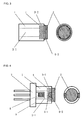
- Fig. 1 is a view showing a configuration of an optical component according to a first embodiment used in a light emitting apparatus of the present invention.
- the optical component according to the first embodiment includes a fixed member 1 and a wavelength conversion member 2.
- the fixed member 1 includes a fit-in part 3-2 in which the wavelength conversion member 2 is fitted, and a through hole 3-1 that contacts the fit-in part 3-2 with a step 4 in between.
- the outer shape of the fixed member 1 may be any shape such as circular, rectangular, and elliptical as long as it is a tubular body, but is preferably circular.
- the transverse cross sectional shape of an inner hole part of the tubular body, or the through hole 3-1 and the fit-in part 3-2 may be any shape such as circular, rectangular, and elliptical, but is preferably circular.
- the wavelength conversion member 2 may be of any shape such as column, quadratic prism, elliptic cylinder, sphere, hemisphere etc., but is preferably a column.
- the wavelength conversion member 2 is arranged in the fit-in part 3-2 of the fixed member 1, and is fixed to the fixed member 1 by filling a cut-in part 5-1 formed at the side surface of the fit-in part 3-2 with the fixing member 5-2. Any number of cut-in parts 5-1 may be formed, but is preferably equally arranged at the periphery of the wavelength conversion member 2.
- the fixing method of the fixed member 1 and the wavelength conversion member 2 is that the wavelength conversion member 2 is fixed to the fixed member 1 by pushing the fixing member (low melting point glass) 5-2, which is molded so as to comply with the shape of the cut-in part in advance, onto the cut-in part 5-1 with the wavelength conversion member 2 arranged in the fit-in part 3-2 of the fixed member 1, and performing heating in this state to fill the fixing member 5-2 in the cut-in part 5-1.
- the fixing member (low melting point glass) 5-2 which is molded so as to comply with the shape of the cut-in part in advance
- the material of the fixed member 1 is preferably a material that has an anti-corrosion property and that easily adheres to the low melting point glass, and stainless material may be used.
- the attachment of the wavelength conversion member 2 to the fixed member 1 is reliably performed with the fixing member 5-2 of a smaller amount than in the attaching method (see Fig. 3 ) in which the low melting point glass is arranged on the side surface of the wavelength conversion member, and thus the affect of the fixing member 5-2 on properties such as light absorption is small. Therefore, according to the first embodiment, the light that exits from the wavelength conversion member 2 is discharged without being attenuated, thereby improving the light emitting efficiency.
- Fig. 2 is a view showing a configuration of an optical component according to a second embodiment used in the light emitting apparatus of the present invention.
- the optical component according to the second embodiment includes a fixed member 1 and a wavelength conversion member 2.
- the fixed member 1 includes a fit-in part 3-2 in which the wavelength conversion member 2 is fitted, and a through hole 3-1 that contacts the fit-in part 3-2 with a step 4 in between.
- the outer shape of the fixed member 1 may be any shape such as circular, rectangular, and elliptical as long as it is a tubular body, but is preferably circular.
- the transverse cross sectional shape of an inner hole part of the tubular body, or the through hole 3-1 and the fit-in part 3-2, may be any shape such as circular, rectangular, and elliptical, but is preferably circular.
- the wavelength conversion member 2 may be of any shape such as column, quadratic prism, elliptic cylinder, sphere, and hemisphere, but is preferably a column.
- the wavelength conversion member 2 is arranged in the fit-in part 3-2 of the fixed member 1, and is fixed to the fixed member 1 by filling a hole part 6-1 formed at the side surface of the fit-in part 3-2 with the fixing member 6-2. Any number of hole parts 6-1 may be formed, but is preferably equally arranged at the periphery of the wavelength conversion member 2.
- the fixing method of the fixed member 1 and the wavelength conversion member 2 is that the wavelength conversion member 2 is fixed to the fixed member 1 by filling the granulated low melting point glass 6-2 serving as the fixing member into the hole part 6-1 with the wavelength conversion member 2 arranged in the fit-in part 3-2 of the fixed member 1, and performing heating in this state.
- the attachment of the wavelength conversion member 2 to the fixed member 1 is reliably performed with a small amount of fixing member 6-2, and thus the affect of the fixing member 6-2 on properties such as light absorption is small. Therefore, according to the second embodiment, the light that exits from the wavelength conversion member 2 is discharged without being attenuated, thereby improving the light emitting efficiency.
- Fig. 3 is a view showing a configuration of an optical component of a comparative example through an attaching method in which the fixing member is arranged on the side surface of the wavelength conversion member.
- the optical component with the low melting point glass arranged on the side surface of the wavelength conversion member includes a fixed member 1 and a wavelength conversion member 2.
- the fixed member 1 includes a fit-in part 3-2 in which the wavelength conversion member 2 is fitted, and a through hole 3-1 that contacts the fit-in part 3-2 with a step 4 in between, but differs from the optical components shown in Figs. 1 and 2 in that a cut-in part nor a hole part is formed at the side surface of the fit-in part 3-2.
- the fixed member 1 is a tubular body having a circular inner hole.
- the wavelength conversion member 2 has a columnar shape.
- the fixing method of the fixed member 1 and the wavelength conversion member 2 is that the wavelength conversion member 2 is fixed to the fixed member 1 by inserting the low melting point glass 6-3 molded into a ring shape in the wavelength conversion member 2 with the wavelength conversion member 2 arranged in the fit-in part 3-2 of the fixed member 1, and performing heating in this state.
- the fixed member 1 and the wavelength conversion member 2 cannot be fixed with a small amount of fixing member 6-3 since the cut-in part nor the hole part is formed at the side surface of the fit-in part 3-2 of the fixed member 1, and the fixing member 6-3 must be arranged around the entire periphery of the wavelength conversion member 2.
- the fixed portion of the fixed member 1 and the wavelength conversion member 2 has a shape in which the low melting point glass is arranged at the side surface of the wavelength conversion member. In this case, some of the light that exits from the wavelength conversion member 2 is absorbed by the fixing member 6-3 and shielded, whereby the light emitting efficiently lowers.
- Fig. 4 is a view showing a configuration of a light emitting apparatus of the present invention equipped with an optical component according to the first embodiment.
- the light emitting device shown in Fig. 4 has a mounting platform 7 fixed to the through hole 3-1 side arranged opposite the fit-in part 3-2, which is fitted with the wavelength conversion member 2, of the fixed member 1 by way of a joining part 9.
- the fixing method includes weld fixation, fixing agent fixation, and brazing.
- a light source 8 is arranged on the mounting platform 7, and is arranged at a position where the light that exits from the light source 8 is efficiently guided to the wavelength conversion member.
- the attachment of the wavelength conversion member 2 to the fixed member 1 is reliably performed with a small amount of fixing member 5-2, and thus none of the fixing member 5-2 goes around to the through hole 3-1 side, and properties such as light absorption will not be affected. Therefore, the light that exits from the light source 8 is guided to the wavelength conversion member 2 without being attenuated, and the light emitting efficiency can be improved.
- the light source 8 emits light having a light emission peak within the wavelength region of 300nm to 500nm, and a light emitting diode, a semiconductor laser element etc. is used as the light source.
- Fig. 5 is a view showing a configuration of another light emitting device equipped with the optical component according to the first embodiment of the present invention.
- the light emitting device shown in Fig. 5 has a light guide holding member 11 arranged with a light guide 10 fixed to the through hole 3-1 side arranged opposite the fit-in part 3-2, which is fitted with the wavelength conversion member 2, of the fixed member 1 by way of a joining part 12 arranged on the side surface of the fixed member 1.
- the fixing method includes weld fixation and fixing agent fixation.
- the fixed member 1 and the light guide holding member 11 can be weld fixed through, e.g. YAG laser welding.
- YAG laser welding the YAG laser is irradiated onto the fixed member 1 to melt the fixed member 1, thereby weld fixing the fixed member 1 and the light guide holding member 11. Therefore, the portion weld fixed by the YAG welding becomes the joining part 12.
- fixing agent fixation a hole is formed at the side surface of the fixed member 1 in advance, and after the light guide holding member 11 is inserted into the through hole 3-1, the fixing material is filled into the hole formed at the side surface of the fixed member 1, thereby fixing with fixing agent the fixed member 1 and the light guide holding member 11. Therefore, the portion fixed by the fixing material becomes the joining part 12.
- the attachment of the wavelength conversion member 2 to the fixed member 1 is reliably performed with a small amount of fixing member 5-2, and thus none of the fixing member 5-2 goes around to the through hole 3-1 side, and the light guide 10 can be brought closer to the wavelength conversion member 2. Therefore, the light that exits from the light guide 10 is guided to the wavelength conversion member 2 without being attenuated, thereby improving the light emitting efficiency.
- the glass used for the wavelength conversion member is preferably silicate glass.
- silicate glass containing one or more types of alkali metal oxide, alkali earth metal oxide, boron oxide, phosphorus oxide, zinc oxide is preferable.
- the wavelength conversion member is obtained by mixing fluorescent material powder and glass powder, and performing e.g. heat press molding on the mixed powder.
- the fixing material is preferably the low melting point glass having a softening point at lower than or equal to 650°C.
- Fig. 6 is a view showing one part of a light emitting apparatus according to a first example of the present invention.
- the transverse cross sectional shape of the fixed member 1, the through hole 3-1 and the fit-in part 3-2 is circular.
- the outer diameter of the fixed member 1 is 1.25mm
- the inner diameter of the through hole 3-1 is 0.7mm
- the inner diameter of the fit-in part 3-2 is 0.9mm.
- the depth of the fit-in part 3-2 is 0.1mm
- the size of the cut-in part 5-1 is 0.2mm in radius and 0.1mm in depth and is arranged at two locations at opposite angles at the side surface of the fit-in part 3-2.
- the wavelength conversion member 2 also has a columnar shape having a diameter of 0.9mm and a thickness of 0.45mm.
- the wavelength conversion member 2 is fitted in the fit-in part 3-2, and is fixed by filling the fixing member 5-2 to the cut-in part 5-1.
- the material of the fixing member 5-2 used for fixing is the low melting point glass having a softening point at 520°C, and is filled by 0.07mg.
- the light guide holding member 11 arranged with the light guide 10 is inserted into the through hole 3-1 of the fixed member 1, and is fixed by a fixing part 13. YAG laser welding is used for fixing.
- Fig. 7 shows the output characteristic of the light that exits from the wavelength conversion member 2 when the laser light of about 445nm is entered from the incident side of the light guide 10. This is compared with the optical output characteristic of a sample having a shape in which the low melting point glass is arranged on the side surface of the wavelength conversion member as shown in Fig. 3 without using the present invention. As a result, the increase by approximately 1.3 times in light emitting efficiency is achieved by the present invention.
- the present invention can be used in light emitting devices such as light emitting diode and semiconductor laser element.
Landscapes
- Physics & Mathematics (AREA)
- Nonlinear Science (AREA)
- Optics & Photonics (AREA)
- General Physics & Mathematics (AREA)
- Electromagnetism (AREA)
- Engineering & Computer Science (AREA)
- Plasma & Fusion (AREA)
- Semiconductor Lasers (AREA)
- Led Device Packages (AREA)
Abstract
Description
- The present invention relates to a light emitting apparatus equipped with an optical component including a wavelength conversion member for wavelength converting the light from a light source.
- Conventionally, a light source is proposed that transmits the light from the light source to a disperser via a separator such as an optical fiber to disperse the light into a desired pattern or change the color of the light (see Japanese Laid-Open Patent Publication No.
2003-515899 - A can package in which the semiconductor laser element is hermetically sealed is also known. The can package is hermetically sealed by a stem mounted with the semiconductor laser element and a cap having a constant thickness. A glass window for extracting the laser light is formed in the cap, and the glass is fixed to the inner side of the cap by way of resin adhesive.
- However, the conventional light source merely has a disperser attached to the distal end of the separator such as an optical fiber, and thus the light emitting efficiency may not be satisfactory depending on the attaching method, and more improvement is required to be used as an optical component capable of being attached to the end part of the optical fiber.
- As for the can package, the glass is fixed with resin adhesive, and thus organic components are volatilized from the resin adhesive. Such organic components become impurities and attach to the inside of the can package, in particular, to the glass and the exit end part of the semiconductor laser element, thereby lowering the optical output of the laser light.
- It is, therefore, an object of the present invention to provide an optical component that has a simple configuration and that prevents lowering of the optical output.
- According to the present invention, such aim is accomplished in the following manner.
- The present invention relates to a light emitting apparatus including a light source; and an optical component including a fixed member having a through hole, and a wavelength conversion member having at least one part thereof arranged in the through hole, a cut-in part or a hole part being formed in a direction substantially perpendicular to the longitudinal direction of the through hole of the fixed member; where the light from the light source is guided to the wavelength conversion member. A configuration that is simple and that prevents lowering in optical output is thereby achieved.
- The wavelength conversion member is preferably fixed to the fixed member using a fixing member. Therefore, the wavelength conversion member can be reliably fixed to the fixed member. Furthermore, hermetic sealing is realized.
- The fixing member is preferably a low melting point glass. In particular, the low melting point glass having a softening point at lower than or equal to 650°C is preferable. Degradation of the optical component can be thereby suppressed.
- The fixing member is preferably filled in the cut-in part or the hole part formed in the fixed member when fixing the wavelength conversion member to the fixed member using the fixing member. Accordingly, the attachment of the wavelength conversion member to the fixed member is reliably performed with a small amount of fixing member, and thus lowering in optical output due to light absorption by the fixing member can be suppressed.
- In addition to the above configuration, the fixed member may include a projection or a concave part for fitting the wavelength conversion member at the through hole side. When the fixed member has a projection on the through hole side, the wavelength conversion member preferably has a concave part that mates with the projection, or when the fixed member has a concave part on the through hole side, the wavelength conversion member preferably has a projection that fits into the concave part. With this configuration, the wavelength conversion member can be fixed even more reliably.
- Preferably, the fixed member is a tubular body with its inner hole being circular in a transverse cross section. Chips and cracks of the fixed member can be thereby prevented.
- The fixed member preferably includes a step at the through hole. The wavelength conversion member is thereby positioned at the step portion of the fixed member, and thus can always be arranged at a constant position.
- The fixed member preferably has a diameter of at least one part of the through hole the same as or greater than a diameter of the wavelength conversion member. The detachment of the wavelength conversion member from the fixed member is thus less likely to occur.
- The wavelength conversion member is preferably fitted in the through hole of the fixed member. The foreign substances are thus prevented from entering into the through hole.
- The wavelength conversion member is preferably obtained by mixing a fluorescent material in glass. Degradation of the wavelength conversion member can be thereby prevented.
- The wavelength conversion member preferably has a thickness of larger than or equal to 350µm. The wavelength conversion member more preferably has a thickness of larger than or equal to 400µm, and most preferably larger than or equal to 450µm. The wavelength conversion efficiency can thereby be enhanced. The wavelength conversion member used in the present invention wavelength converts the light, and the wavelength conversion efficiency increases as the thickness of the wavelength conversion member becomes thicker, and thus the wavelength conversion member preferably has a thickness of larger than or equal to a predetermined thickness. This is different from the aim of the configuration to have a thinner thickness since the transmissivity of the light lowers when only glass is used as in the conventional can package.
- The glass is preferably silicate glass. In particular, silicate glass containing one or more types of alkali metal oxide, alkali earth metal oxide, boron oxide, phosphorus oxide, zinc oxide is preferable. The resistance to weather of the wavelength conversion member thereby enhances, and degradation of the wavelength conversion member can be prevented.
- The light source preferably emits light having a light emission peak within the wavelength region of 300nm to 500nm. A light source having high energy thus can be used in a visible light region.
- The fixed member may adopt a configuration connected to a light guide for guiding the light from the light source. A configuration in which the light source and the wavelength conversion member are spaced apart so that heat from the light source is not directly transmitted can be achieved.
- According to the present invention, an optical component that has a simple configuration and that prevents lowering of optical output is achieved.
-
-
Fig. 1 is a view showing a configuration of an optical component according to a first embodiment used in a light emitting apparatus of the present invention; -
Fig. 2 is a view showing a configuration of an optical component according to a second embodiment used in the light emitting apparatus of the present invention; -
Fig. 3 is a view showing a configuration of an optical component of a comparative example in which a fixing member is arranged on the side surface of the waveform conversion member; -
Fig. 4 is a view showing a configuration of a light emitting apparatus of the present invention equipped with an optical component according to the first embodiment; -
Fig. 5 is a view showing a configuration of a light emitting apparatus according to another embodiment of the present invention; -
Fig. 6 is a view showing one part of a light emitting apparatus according to a first example of the present invention; and -
Fig. 7 is a view showing the effects of the first example of the present invention. - The preferred embodiments according to the present invention will now be described in detail with reference to the accompanying drawings.
-
Fig. 1 is a view showing a configuration of an optical component according to a first embodiment used in a light emitting apparatus of the present invention. - As shown in
Fig. 1 , the optical component according to the first embodiment includes afixed member 1 and awavelength conversion member 2. Thefixed member 1 includes a fit-in part 3-2 in which thewavelength conversion member 2 is fitted, and a through hole 3-1 that contacts the fit-in part 3-2 with astep 4 in between. The outer shape of thefixed member 1 may be any shape such as circular, rectangular, and elliptical as long as it is a tubular body, but is preferably circular. The transverse cross sectional shape of an inner hole part of the tubular body, or the through hole 3-1 and the fit-in part 3-2, may be any shape such as circular, rectangular, and elliptical, but is preferably circular. Thewavelength conversion member 2 may be of any shape such as column, quadratic prism, elliptic cylinder, sphere, hemisphere etc., but is preferably a column. Thewavelength conversion member 2 is arranged in the fit-in part 3-2 of the fixedmember 1, and is fixed to the fixedmember 1 by filling a cut-in part 5-1 formed at the side surface of the fit-in part 3-2 with the fixing member 5-2. Any number of cut-in parts 5-1 may be formed, but is preferably equally arranged at the periphery of thewavelength conversion member 2. - The fixing method of the fixed
member 1 and thewavelength conversion member 2 is that thewavelength conversion member 2 is fixed to the fixedmember 1 by pushing the fixing member (low melting point glass) 5-2, which is molded so as to comply with the shape of the cut-in part in advance, onto the cut-in part 5-1 with thewavelength conversion member 2 arranged in the fit-in part 3-2 of the fixedmember 1, and performing heating in this state to fill the fixing member 5-2 in the cut-in part 5-1. - The material of the fixed
member 1 is preferably a material that has an anti-corrosion property and that easily adheres to the low melting point glass, and stainless material may be used. - According to the first embodiment, the attachment of the
wavelength conversion member 2 to the fixedmember 1 is reliably performed with the fixing member 5-2 of a smaller amount than in the attaching method (seeFig. 3 ) in which the low melting point glass is arranged on the side surface of the wavelength conversion member, and thus the affect of the fixing member 5-2 on properties such as light absorption is small. Therefore, according to the first embodiment, the light that exits from thewavelength conversion member 2 is discharged without being attenuated, thereby improving the light emitting efficiency. -
Fig. 2 is a view showing a configuration of an optical component according to a second embodiment used in the light emitting apparatus of the present invention. - As shown in
Fig. 2 , the optical component according to the second embodiment includes a fixedmember 1 and awavelength conversion member 2. The fixedmember 1 includes a fit-in part 3-2 in which thewavelength conversion member 2 is fitted, and a through hole 3-1 that contacts the fit-in part 3-2 with astep 4 in between. The outer shape of the fixedmember 1 may be any shape such as circular, rectangular, and elliptical as long as it is a tubular body, but is preferably circular. The transverse cross sectional shape of an inner hole part of the tubular body, or the through hole 3-1 and the fit-in part 3-2, may be any shape such as circular, rectangular, and elliptical, but is preferably circular. Thewavelength conversion member 2 may be of any shape such as column, quadratic prism, elliptic cylinder, sphere, and hemisphere, but is preferably a column. Thewavelength conversion member 2 is arranged in the fit-in part 3-2 of the fixedmember 1, and is fixed to the fixedmember 1 by filling a hole part 6-1 formed at the side surface of the fit-in part 3-2 with the fixing member 6-2. Any number of hole parts 6-1 may be formed, but is preferably equally arranged at the periphery of thewavelength conversion member 2. - The fixing method of the fixed
member 1 and thewavelength conversion member 2 is that thewavelength conversion member 2 is fixed to the fixedmember 1 by filling the granulated low melting point glass 6-2 serving as the fixing member into the hole part 6-1 with thewavelength conversion member 2 arranged in the fit-in part 3-2 of the fixedmember 1, and performing heating in this state. - According to the second embodiment, the attachment of the
wavelength conversion member 2 to the fixedmember 1 is reliably performed with a small amount of fixing member 6-2, and thus the affect of the fixing member 6-2 on properties such as light absorption is small. Therefore, according to the second embodiment, the light that exits from thewavelength conversion member 2 is discharged without being attenuated, thereby improving the light emitting efficiency. -
Fig. 3 is a view showing a configuration of an optical component of a comparative example through an attaching method in which the fixing member is arranged on the side surface of the wavelength conversion member. - As shown in
Fig. 3 , the optical component with the low melting point glass arranged on the side surface of the wavelength conversion member includes a fixedmember 1 and awavelength conversion member 2. The fixedmember 1 includes a fit-in part 3-2 in which thewavelength conversion member 2 is fitted, and a through hole 3-1 that contacts the fit-in part 3-2 with astep 4 in between, but differs from the optical components shown inFigs. 1 and 2 in that a cut-in part nor a hole part is formed at the side surface of the fit-in part 3-2. The fixedmember 1 is a tubular body having a circular inner hole. Thewavelength conversion member 2 has a columnar shape. The fixing method of the fixedmember 1 and thewavelength conversion member 2 is that thewavelength conversion member 2 is fixed to the fixedmember 1 by inserting the low melting point glass 6-3 molded into a ring shape in thewavelength conversion member 2 with thewavelength conversion member 2 arranged in the fit-in part 3-2 of the fixedmember 1, and performing heating in this state. - In the optical component shown in
Fig. 3 , the fixedmember 1 and thewavelength conversion member 2 cannot be fixed with a small amount of fixing member 6-3 since the cut-in part nor the hole part is formed at the side surface of the fit-in part 3-2 of the fixedmember 1, and the fixing member 6-3 must be arranged around the entire periphery of thewavelength conversion member 2. Thus, the fixed portion of the fixedmember 1 and thewavelength conversion member 2 has a shape in which the low melting point glass is arranged at the side surface of the wavelength conversion member. In this case, some of the light that exits from thewavelength conversion member 2 is absorbed by the fixing member 6-3 and shielded, whereby the light emitting efficiently lowers. -
Fig. 4 is a view showing a configuration of a light emitting apparatus of the present invention equipped with an optical component according to the first embodiment. - The light emitting device shown in
Fig. 4 has a mountingplatform 7 fixed to the through hole 3-1 side arranged opposite the fit-in part 3-2, which is fitted with thewavelength conversion member 2, of the fixedmember 1 by way of a joining part 9. The fixing method includes weld fixation, fixing agent fixation, and brazing. Alight source 8 is arranged on the mountingplatform 7, and is arranged at a position where the light that exits from thelight source 8 is efficiently guided to the wavelength conversion member. - The attachment of the
wavelength conversion member 2 to the fixedmember 1 is reliably performed with a small amount of fixing member 5-2, and thus none of the fixing member 5-2 goes around to the through hole 3-1 side, and properties such as light absorption will not be affected. Therefore, the light that exits from thelight source 8 is guided to thewavelength conversion member 2 without being attenuated, and the light emitting efficiency can be improved. Thelight source 8 emits light having a light emission peak within the wavelength region of 300nm to 500nm, and a light emitting diode, a semiconductor laser element etc. is used as the light source. -
Fig. 5 is a view showing a configuration of another light emitting device equipped with the optical component according to the first embodiment of the present invention. - The light emitting device shown in
Fig. 5 has a lightguide holding member 11 arranged with alight guide 10 fixed to the through hole 3-1 side arranged opposite the fit-in part 3-2, which is fitted with thewavelength conversion member 2, of the fixedmember 1 by way of a joiningpart 12 arranged on the side surface of the fixedmember 1. The fixing method includes weld fixation and fixing agent fixation. - In weld fixation, the fixed
member 1 and the lightguide holding member 11 can be weld fixed through, e.g. YAG laser welding. In YAG laser welding, the YAG laser is irradiated onto the fixedmember 1 to melt the fixedmember 1, thereby weld fixing the fixedmember 1 and the lightguide holding member 11. Therefore, the portion weld fixed by the YAG welding becomes the joiningpart 12. - In fixing agent fixation, a hole is formed at the side surface of the fixed
member 1 in advance, and after the lightguide holding member 11 is inserted into the through hole 3-1, the fixing material is filled into the hole formed at the side surface of the fixedmember 1, thereby fixing with fixing agent the fixedmember 1 and the lightguide holding member 11. Therefore, the portion fixed by the fixing material becomes the joiningpart 12. - The attachment of the
wavelength conversion member 2 to the fixedmember 1 is reliably performed with a small amount of fixing member 5-2, and thus none of the fixing member 5-2 goes around to the through hole 3-1 side, and thelight guide 10 can be brought closer to thewavelength conversion member 2. Therefore, the light that exits from thelight guide 10 is guided to thewavelength conversion member 2 without being attenuated, thereby improving the light emitting efficiency. - The glass used for the wavelength conversion member is preferably silicate glass. In particular, silicate glass containing one or more types of alkali metal oxide, alkali earth metal oxide, boron oxide, phosphorus oxide, zinc oxide is preferable. The wavelength conversion member is obtained by mixing fluorescent material powder and glass powder, and performing e.g. heat press molding on the mixed powder.
- The fixing material is preferably the low melting point glass having a softening point at lower than or equal to 650°C.
-
Fig. 6 is a view showing one part of a light emitting apparatus according to a first example of the present invention. - In the first example, the transverse cross sectional shape of the fixed
member 1, the through hole 3-1 and the fit-in part 3-2 is circular. The outer diameter of the fixedmember 1 is 1.25mm, the inner diameter of the through hole 3-1 is 0.7mm, and the inner diameter of the fit-in part 3-2 is 0.9mm. The depth of the fit-in part 3-2 is 0.1mm, and the size of the cut-in part 5-1 is 0.2mm in radius and 0.1mm in depth and is arranged at two locations at opposite angles at the side surface of the fit-in part 3-2. Thewavelength conversion member 2 also has a columnar shape having a diameter of 0.9mm and a thickness of 0.45mm. Thewavelength conversion member 2 is fitted in the fit-in part 3-2, and is fixed by filling the fixing member 5-2 to the cut-in part 5-1. The material of the fixing member 5-2 used for fixing is the low melting point glass having a softening point at 520°C, and is filled by 0.07mg. The lightguide holding member 11 arranged with thelight guide 10 is inserted into the through hole 3-1 of the fixedmember 1, and is fixed by a fixingpart 13. YAG laser welding is used for fixing. -
Fig. 7 shows the output characteristic of the light that exits from thewavelength conversion member 2 when the laser light of about 445nm is entered from the incident side of thelight guide 10. This is compared with the optical output characteristic of a sample having a shape in which the low melting point glass is arranged on the side surface of the wavelength conversion member as shown inFig. 3 without using the present invention. As a result, the increase by approximately 1.3 times in light emitting efficiency is achieved by the present invention. - The present invention can be used in light emitting devices such as light emitting diode and semiconductor laser element.
Claims (10)
- A light emitting apparatus comprising:a light source; andan optical component including a fixed member (1) with a through hole (3-1) and a wavelength conversion member (2),wherein the light source (8) is arranged on a mounting platform 7, which is fixed to the through hole (3-1) side arranged opposite the fit-in part (3-2),
the fixed member (1) including- a fit-in part (3-2) in which the wavelength conversion member (2) is fitted, whereby the through hole (3-1) contacts the fit-in part (3-2) with a step (4) in between,- and a cut-in part or a hole part being formed at the fit-in part (3-2);
the light from said light source is guided to said wavelength conversion member. - The light emitting apparatus according to claim 1, wherein said wavelength conversion member is fixed to said fixed member using a fixing member.
- The light emitting apparatus according to claim 2, wherein said fixing member is low melting point glass.
- The light emitting apparatus according to claim 2 or 3, wherein said fixing member is filled into said cut-in part or said hole part.
- The light emitting apparatus according to claim 1, wherein said fixed member is a tubular body and has an inner hole whose transverse cross sectional shape is circular shape.
- The light emitting apparatus according to claim 1 or 5, wherein said fixed member includes a step at said through hole.
- The light emitting apparatus according to any one of claims 1, 5 and 6, wherein a diameter of at least one part of said through hole in said fixed member is the same as or larger than a diameter of said wavelength conversion member.
- The light emitting apparatus according to any one of claims 1 and 5 to 7, wherein said wavelength conversion member is obtained by mixing a fluorescent material in glass.
- The light emitting apparatus according to claim 8, wherein said glass is silicate glass.
- The light emitting apparatus according to any one of claims 1 to 9, wherein said light source emits light having a light emission peak within the wavelength region of 300nm to 500nm.
Applications Claiming Priority (2)
| Application Number | Priority Date | Filing Date | Title |
|---|---|---|---|
| JP2006150553A JP2007324239A (en) | 2006-05-30 | 2006-05-30 | Light emitting device |
| EP07009734.0A EP1862141B1 (en) | 2006-05-30 | 2007-05-15 | Light emitting apparatus |
Related Parent Applications (2)
| Application Number | Title | Priority Date | Filing Date |
|---|---|---|---|
| EP07009734.0A Division EP1862141B1 (en) | 2006-05-30 | 2007-05-15 | Light emitting apparatus |
| EP07009734.0A Division-Into EP1862141B1 (en) | 2006-05-30 | 2007-05-15 | Light emitting apparatus |
Publications (3)
| Publication Number | Publication Date |
|---|---|
| EP2009708A2 true EP2009708A2 (en) | 2008-12-31 |
| EP2009708A3 EP2009708A3 (en) | 2009-02-18 |
| EP2009708B1 EP2009708B1 (en) | 2020-01-15 |
Family
ID=38335583
Family Applications (2)
| Application Number | Title | Priority Date | Filing Date |
|---|---|---|---|
| EP07009734.0A Not-in-force EP1862141B1 (en) | 2006-05-30 | 2007-05-15 | Light emitting apparatus |
| EP08166586.1A Ceased EP2009708B1 (en) | 2006-05-30 | 2007-05-15 | Light emitting apparatus |
Family Applications Before (1)
| Application Number | Title | Priority Date | Filing Date |
|---|---|---|---|
| EP07009734.0A Not-in-force EP1862141B1 (en) | 2006-05-30 | 2007-05-15 | Light emitting apparatus |
Country Status (3)
| Country | Link |
|---|---|
| US (1) | US7843124B2 (en) |
| EP (2) | EP1862141B1 (en) |
| JP (1) | JP2007324239A (en) |
Families Citing this family (4)
| Publication number | Priority date | Publication date | Assignee | Title |
|---|---|---|---|---|
| JP4638837B2 (en) * | 2006-05-30 | 2011-02-23 | 日本電気硝子株式会社 | Optical component and light emitting device |
| US9693826B2 (en) | 2008-02-28 | 2017-07-04 | Biolitec Unternehmensbeteiligungs Ii Ag | Endoluminal laser ablation device and method for treating veins |
| JP2009289976A (en) * | 2008-05-29 | 2009-12-10 | Nichia Corp | Light emitting device |
| JP2012095911A (en) * | 2010-11-04 | 2012-05-24 | Fujifilm Corp | Endoscope and light source device for endoscope |
Citations (1)
| Publication number | Priority date | Publication date | Assignee | Title |
|---|---|---|---|---|
| JP2003515899A (en) | 1999-12-03 | 2003-05-07 | クリー・ライティング・カンパニー | Solid lamp |
Family Cites Families (23)
| Publication number | Priority date | Publication date | Assignee | Title |
|---|---|---|---|---|
| US3550095A (en) * | 1967-05-02 | 1970-12-22 | Matsushita Electric Industrial Co Ltd | Luminescent memory and display device |
| FR2503388A1 (en) * | 1981-04-06 | 1982-10-08 | Socapex | CONNECTOR END FOR OPTIC FIBER, METHOD FOR CENTERING FIBER THEREIN AND DEVICE FOR IMPLEMENTING SAID METHOD |
| JPS5834887A (en) * | 1981-08-26 | 1983-03-01 | Toshiba Corp | Suspension of fluorescent material |
| JPS6057808A (en) | 1983-09-10 | 1985-04-03 | Fujitsu Ltd | Ferrule for optical connector |
| DE3431748A1 (en) | 1984-08-29 | 1986-03-13 | Siemens AG, 1000 Berlin und 8000 München | Device for the sealed bushing of an optical waveguide |
| JPS61144613A (en) * | 1984-12-18 | 1986-07-02 | Fujitsu Ltd | Fixing method of optical parts |
| US4789992A (en) | 1985-10-15 | 1988-12-06 | Luxtron Corporation | Optical temperature measurement techniques |
| US4695697A (en) | 1985-12-13 | 1987-09-22 | Gv Medical, Inc. | Fiber tip monitoring and protection assembly |
| JPH01167812A (en) * | 1987-12-24 | 1989-07-03 | Matsushita Electric Ind Co Ltd | Optical fiber cable |
| JPH0486705A (en) | 1990-07-31 | 1992-03-19 | Canon Inc | Light guide |
| JPH05176208A (en) * | 1991-10-14 | 1993-07-13 | Sony Corp | Video camera |
| FR2693559B1 (en) | 1992-07-13 | 1994-08-26 | Sept Doloy Sa | Hermetic passage of an optical fiber in a metal tube. |
| JPH07272302A (en) * | 1994-03-31 | 1995-10-20 | Matsushita Electric Ind Co Ltd | Objective lens device |
| US5734762A (en) * | 1995-09-15 | 1998-03-31 | Qualop Systems Corporation | Optical isolator system and method |
| US5661829A (en) * | 1996-03-19 | 1997-08-26 | Oplink Communications, Inc. | Optical isolator |
| JP4004705B2 (en) * | 2000-02-29 | 2007-11-07 | 松下電器産業株式会社 | Imaging device and imaging device assembling method |
| US6631220B1 (en) * | 2000-07-07 | 2003-10-07 | Optiwork, Inc. | Optical isolator |
| TW506537U (en) * | 2001-11-21 | 2002-10-11 | Hon Hai Prec Ind Co Ltd | Optical fiber collimator |
| TW505241U (en) * | 2001-12-12 | 2002-10-01 | Hon Hai Prec Ind Co Ltd | Optical fiber isolator |
| KR100443987B1 (en) * | 2002-02-14 | 2004-08-09 | 삼성전자주식회사 | Soldering apparatus for collimator and soldering method thereof |
| JP4158012B2 (en) * | 2002-03-06 | 2008-10-01 | 日本電気硝子株式会社 | Luminescent color conversion member |
| US6956243B1 (en) * | 2004-07-23 | 2005-10-18 | Unity Opto Technology Co., Ltd | Light emitting diode |
| JP4638837B2 (en) * | 2006-05-30 | 2011-02-23 | 日本電気硝子株式会社 | Optical component and light emitting device |
-
2006
- 2006-05-30 JP JP2006150553A patent/JP2007324239A/en not_active Withdrawn
-
2007
- 2007-05-15 EP EP07009734.0A patent/EP1862141B1/en not_active Not-in-force
- 2007-05-15 EP EP08166586.1A patent/EP2009708B1/en not_active Ceased
- 2007-05-24 US US11/802,760 patent/US7843124B2/en active Active
Patent Citations (1)
| Publication number | Priority date | Publication date | Assignee | Title |
|---|---|---|---|---|
| JP2003515899A (en) | 1999-12-03 | 2003-05-07 | クリー・ライティング・カンパニー | Solid lamp |
Non-Patent Citations (1)
| Title |
|---|
| NARENDRAN N. ET AL.: "Journal of Crystal Growth", vol. 268, 1 August 2004, ELSEVIER, article "Solid-state lighting: failure analysis of white LEDs", pages: 449 - 456 |
Also Published As
| Publication number | Publication date |
|---|---|
| JP2007324239A (en) | 2007-12-13 |
| EP2009708A3 (en) | 2009-02-18 |
| US7843124B2 (en) | 2010-11-30 |
| EP2009708B1 (en) | 2020-01-15 |
| US20070279928A1 (en) | 2007-12-06 |
| EP1862141B1 (en) | 2018-08-22 |
| EP1862141A1 (en) | 2007-12-05 |
Similar Documents
| Publication | Publication Date | Title |
|---|---|---|
| EP1903361B1 (en) | Optical component and light emitting device using the same | |
| JP5287275B2 (en) | Light emitting device | |
| US6071017A (en) | Optical package with alignment means and method of assembling an optical package | |
| EP1862140A1 (en) | Optical component | |
| US6550983B1 (en) | Optical package with alignment means and method of assembling an optical package | |
| US7843124B2 (en) | Light emitting apparatus | |
| US11933485B2 (en) | Hermetically sealed LED light and method for manufacturing a hermetically sealed LED light | |
| JPWO2016185537A1 (en) | Endoscope and light transmission module | |
| CN101178465A (en) | optical module | |
| US20050105857A1 (en) | Ferrule block and optical module using the same | |
| US7572068B2 (en) | Laser module having detachable transparent member covering light-output window | |
| US20070019694A1 (en) | Laser module having controlled optical power density at exposed surfaces | |
| WO2010098277A1 (en) | Optical semiconductor device | |
| US6623176B2 (en) | Optical fiber assembly and method for suppressing optical instabilities due to improperly cured epoxy | |
| KR20110020174A (en) | Optical device and its manufacturing method | |
| US7309175B1 (en) | Reducing heating from non-coupled light in power transmitting optical fibers | |
| JP2008046520A (en) | Optical connector, optical fiber module, and method of assembling the same | |
| US20190129108A1 (en) | Modular Laser Connector Packaging System and Method | |
| JP4085919B2 (en) | Optical module | |
| WO2009025662A1 (en) | Reducing heating from non-coupled light in power transmitting optical fibers | |
| JP2005217004A (en) | Optical communication module | |
| JP4731251B2 (en) | Endoscope | |
| JPS6352108A (en) | Photoelectron device and its manufacture | |
| JP2560135B2 (en) | Method for filling transparent resin in semiconductor laser device | |
| EP3229052A1 (en) | Optical fiber affixing structure, semiconductor laser module and method for producing semiconductor laser module |
Legal Events
| Date | Code | Title | Description |
|---|---|---|---|
| PUAI | Public reference made under article 153(3) epc to a published international application that has entered the european phase |
Free format text: ORIGINAL CODE: 0009012 |
|
| AC | Divisional application: reference to earlier application |
Ref document number: 1862141 Country of ref document: EP Kind code of ref document: P |
|
| AK | Designated contracting states |
Kind code of ref document: A2 Designated state(s): AT BE BG CH CY CZ DE DK EE ES FI FR GB GR HU IE IS IT LI LT LU LV MC MT NL PL PT RO SE SI SK TR |
|
| AX | Request for extension of the european patent |
Extension state: AL BA HR MK RS |
|
| PUAL | Search report despatched |
Free format text: ORIGINAL CODE: 0009013 |
|
| AK | Designated contracting states |
Kind code of ref document: A3 Designated state(s): AT BE BG CH CY CZ DE DK EE ES FI FR GB GR HU IE IS IT LI LT LU LV MC MT NL PL PT RO SE SI SK TR |
|
| AX | Request for extension of the european patent |
Extension state: AL BA HR MK RS |
|
| 17P | Request for examination filed |
Effective date: 20090814 |
|
| AKX | Designation fees paid |
Designated state(s): DE FR GB |
|
| 17Q | First examination report despatched |
Effective date: 20090929 |
|
| RIC1 | Information provided on ipc code assigned before grant |
Ipc: H01L 33/50 20100101ALI20110627BHEP Ipc: H01L 33/48 20100101AFI20110627BHEP |
|
| GRAP | Despatch of communication of intention to grant a patent |
Free format text: ORIGINAL CODE: EPIDOSNIGR1 |
|
| GRAS | Grant fee paid |
Free format text: ORIGINAL CODE: EPIDOSNIGR3 |
|
| GRAJ | Information related to disapproval of communication of intention to grant by the applicant or resumption of examination proceedings by the epo deleted |
Free format text: ORIGINAL CODE: EPIDOSDIGR1 |
|
| INTC | Intention to grant announced (deleted) | ||
| GRAP | Despatch of communication of intention to grant a patent |
Free format text: ORIGINAL CODE: EPIDOSNIGR1 |
|
| INTG | Intention to grant announced |
Effective date: 20190605 |
|
| GRAS | Grant fee paid |
Free format text: ORIGINAL CODE: EPIDOSNIGR3 |
|
| GRAA | (expected) grant |
Free format text: ORIGINAL CODE: 0009210 |
|
| AC | Divisional application: reference to earlier application |
Ref document number: 1862141 Country of ref document: EP Kind code of ref document: P |
|
| AK | Designated contracting states |
Kind code of ref document: B1 Designated state(s): DE FR GB |
|
| REG | Reference to a national code |
Ref country code: GB Ref legal event code: FG4D |
|
| REG | Reference to a national code |
Ref country code: DE Ref legal event code: R096 Ref document number: 602007059773 Country of ref document: DE |
|
| REG | Reference to a national code |
Ref country code: DE Ref legal event code: R097 Ref document number: 602007059773 Country of ref document: DE |
|
| PLBE | No opposition filed within time limit |
Free format text: ORIGINAL CODE: 0009261 |
|
| STAA | Information on the status of an ep patent application or granted ep patent |
Free format text: STATUS: NO OPPOSITION FILED WITHIN TIME LIMIT |
|
| 26N | No opposition filed |
Effective date: 20201016 |
|
| PGFP | Annual fee paid to national office [announced via postgrant information from national office to epo] |
Ref country code: FR Payment date: 20210412 Year of fee payment: 15 |
|
| PGFP | Annual fee paid to national office [announced via postgrant information from national office to epo] |
Ref country code: GB Payment date: 20210422 Year of fee payment: 15 |
|
| PGFP | Annual fee paid to national office [announced via postgrant information from national office to epo] |
Ref country code: DE Payment date: 20220329 Year of fee payment: 16 |
|
| GBPC | Gb: european patent ceased through non-payment of renewal fee |
Effective date: 20220515 |
|
| PG25 | Lapsed in a contracting state [announced via postgrant information from national office to epo] |
Ref country code: FR Free format text: LAPSE BECAUSE OF NON-PAYMENT OF DUE FEES Effective date: 20220531 |
|
| PG25 | Lapsed in a contracting state [announced via postgrant information from national office to epo] |
Ref country code: GB Free format text: LAPSE BECAUSE OF NON-PAYMENT OF DUE FEES Effective date: 20220515 |
|
| P01 | Opt-out of the competence of the unified patent court (upc) registered |
Effective date: 20230522 |
|
| REG | Reference to a national code |
Ref country code: DE Ref legal event code: R119 Ref document number: 602007059773 Country of ref document: DE |
|
| PG25 | Lapsed in a contracting state [announced via postgrant information from national office to epo] |
Ref country code: DE Free format text: LAPSE BECAUSE OF NON-PAYMENT OF DUE FEES Effective date: 20231201 |