EP2009732B1 - Abstimmbare Lambda-Viertel Filterbaugruppe - Google Patents
Abstimmbare Lambda-Viertel Filterbaugruppe Download PDFInfo
- Publication number
- EP2009732B1 EP2009732B1 EP08010853A EP08010853A EP2009732B1 EP 2009732 B1 EP2009732 B1 EP 2009732B1 EP 08010853 A EP08010853 A EP 08010853A EP 08010853 A EP08010853 A EP 08010853A EP 2009732 B1 EP2009732 B1 EP 2009732B1
- Authority
- EP
- European Patent Office
- Prior art keywords
- contact
- short circuit
- circuit means
- electrical
- short
- Prior art date
- Legal status (The legal status is an assumption and is not a legal conclusion. Google has not performed a legal analysis and makes no representation as to the accuracy of the status listed.)
- Not-in-force
Links
- 239000004020 conductor Substances 0.000 claims abstract description 64
- 230000008878 coupling Effects 0.000 claims abstract description 16
- 238000010168 coupling process Methods 0.000 claims abstract description 16
- 238000005859 coupling reaction Methods 0.000 claims abstract description 16
- 238000005516 engineering process Methods 0.000 description 1
- 238000010295 mobile communication Methods 0.000 description 1
Images


Classifications
-
- H—ELECTRICITY
- H01—ELECTRIC ELEMENTS
- H01P—WAVEGUIDES; RESONATORS, LINES, OR OTHER DEVICES OF THE WAVEGUIDE TYPE
- H01P1/00—Auxiliary devices
- H01P1/20—Frequency-selective devices, e.g. filters
- H01P1/201—Filters for transverse electromagnetic waves
- H01P1/202—Coaxial filters
-
- H—ELECTRICITY
- H01—ELECTRIC ELEMENTS
- H01P—WAVEGUIDES; RESONATORS, LINES, OR OTHER DEVICES OF THE WAVEGUIDE TYPE
- H01P1/00—Auxiliary devices
- H01P1/24—Terminating devices
- H01P1/28—Short-circuiting plungers
Definitions
- the invention relates to a tunable ⁇ / 4 filter assembly having a signal-carrying electrical conductor and a lying on a reference potential electrically conductive element, which may be in particular a lying on ground housing.
- ⁇ / 4 filters are used as bandpass filters in high-frequency technology, for example.
- such filters have a short-circuit line of fixed length between a signal-carrying conductor and a ground.
- the bandpass character of such a filter results from the particular wave characteristic at high frequencies, since at high frequencies the short circuit at the center frequency f 0 is hidden, so that signals with frequencies distributed within a certain bandwidth around the center frequency, the conductor can happen.
- Such filters are also used as overvoltage protection, for example in mobile communications.
- an overvoltage protection connector for a coaxial cable which includes an inner and an outer conductor wherein a helical short-circuiting dummy tail of fixed length shorts the inner conductor to the outer conductor.
- an overvoltage protection device in which an inner conductor is arranged in a housing which together form a coaxial line.
- a fixed length helical conductor serves as a shorting element to transfer energy to a ground connection during an overvoltage event.
- the document DE 195 20 974 A1 describes an overvoltage protection for RF lines, with a Koaxial effetsabites comprising an inner conductor and an outer conductor.
- the inner conductor is firmly connected to the outer conductor via inner conductor sections.
- the document WO 2004/004064 describes a lightning arrester device with an inner conductor and a coaxially arranged housing. A pair of two leads connect the inner conductor to the housing.
- the document EP-A-1 772 931 shows a known coaxial cable, wherein short-circuit elements are arranged with a fixed length between the inner conductor and the outer conductor of the coaxial cable.
- US-A-2 438 912 shows an apparatus for impedance matching or impedance coupling.
- the device has an inner conductor and an outer conductor, which are spaced apart by means of insulating discs.
- the device has an inner conductor and an outer conductor, which are electrically insulated from each other by means of a dielectric disk.
- the document DE 15 41 960 A1 describes a narrow band filter assembly having an outer conductor and an inner conductor. Through the inner conductor a sliding stub pierced, which lies in a tube. Short-circuit valves contact the stub conductor with the pipe.
- a disadvantage of the known filter is the fact that due to the fixed short-circuit length, the center frequency is fixed. Consequently, a separate filter must be used for each different frequency response.
- the present invention is therefore an object of the invention to provide a ⁇ / 4 filter assembly, which is universal and can be used for a variable frequency range.
- a key idea of the invention is to provide a tunable ⁇ / 4 filter whose frequency response is variable by the length of a short-circuiting device is adjustable.
- a tunable ⁇ / 4 filter assembly which has a signal carrying having an electrical conductor and a lying on a reference potential electrically conductive element.
- at least one short-circuit device is provided, which electrically contacts the electrical conductor.
- an electrical coupling device is provided which the Short-circuit device coupled to the electrically conductive element at an adjustable contact point, wherein the electrical coupling device and the short-circuiting device are movable relative to each other, so as to be able to adjust the length of the short-circuiting device.
- the length of the short-circuit device is preferably continuously adjustable within a predeterminable length range, whereby the center frequency of the tunable ⁇ / 4 filter assembly is also continuously adjustable. In this way, a ⁇ / 4 filter with variable bandpass performance is achieved.
- the short-circuit device expediently has a first contact section, which is connected to the electrical conductor, and a second contact section adjoining the first contact section, to which the electrical coupling device electrically engages.
- a further short-circuit device which lies in the same plane as the first short-circuit device.
- the further short-circuit device has a first contact section, which is connected to the electrical conductor, and a second contact section adjoining the first contact section, which electrically engages the electrical coupling device.
- the second contact portions of the two short-circuit devices each form a circular segment-shaped conductor element, which is arranged in each case substantially at a distance r around the electrical conductor, wherein the two second contact portions are arranged substantially diametrically opposite each other.
- each second contact portion is preferably smaller than ⁇ r.
- the electrical element is again a conductive housing, which at least partially surrounds the conductor and the short-circuiting device.
- the flexible and powerful coupling device has a first and a second rotatable electrically conductive actuating element, each having a contact element, wherein the actuating elements are movable independently of each other.
- the contact element of the first control element engages an adjustable contact point on the second contact section of the first short-circuit device, while the contact element of the second control element acts on an adjustable contact point on the second contact section of the other short-circuit device.
- In the housing at least one slot for moving the contact elements by means of the adjusting elements is provided, wherein the adjusting elements abut against the housing, so that the adjusting elements and the housing are at the same potential.
- the contact elements are designed as sliding contacts.
- Fig. 1 shows an exemplary ⁇ / 4 filter assembly 10, the center frequency and thus the bandwidth of which is adjustable by means of two short-circuit devices 40 and 50 of variable length.
- the ⁇ / 4 filter assembly 10 shown schematically in longitudinal section has an inner signal-carrying conductor 20 having terminals 25 at its two ends.
- the electrical conductor 20 is preferably held centrally in an electrically conductive housing 30.
- the housing 30 has a circular cross-section, wherein the diameter in the vicinity of the two line ends is smaller than in the middle region of the electrical conductor 20.
- the two short-circuit devices 40 and 50 are soldered, the design of which Fig. 2 is shown in more detail.
- a coupling device 70 which has two electrically conductive rings 73 and 75 as adjusting elements.
- two parallel grooves may be included in which the rings are rotatably guided.
- a sliding contact 72 is formed, which electrically contacts the short-circuiting device 40, while on the ring 75, a sliding contact 77 is integrally formed, which contacts the short-circuiting device 50 electrically.
- slots are provided so that the sliding contacts along the respective short-circuiting device can be moved by means of the rings.
- Fig. 2 shows in cross section the filter assembly 10 and in particular the electrically conductive housing 30, which the electrical conductor 20 and the two short-circuiting devices 40 and 50th at least partially surrounds.
- the short-circuiting device 40 has a first conductor-shaped contact portion 40a, one end of which is electrically connected to the electrical conductor 20 at a predetermined location.
- the ladder-shaped contact portion 40a extends perpendicularly away from the electrical conductor 20 and has a length r.
- a circular segment-shaped contact portion 40b is formed at the outer end of the contact portion 40a.
- the electrical conductor 20 forms the center of the circular segment-shaped contact section 40b, wherein the radius of curvature of the contact section 40b substantially corresponds to the length r.
- the sliding contact 72 of the annular adjusting element 73 engages at a contact point 80 on the circular segment-shaped contact portion 40b.
- the sliding contact 72 moves along the circular segment-shaped contact portion 40b, whereby the contact point 80 and thus the length of the short-circuiting device 40 can be changed continuously.
- the short-circuit connection extends from the conductor 20, via the contact portions 40a and 40b, the contact point 80, the sliding contact 72, the actuating element 73 to the electrically conductive housing 30th
- the in the Fig. 2 illustrated second short-circuit device 50 is similar to the short-circuit device 40 constructed.
- a ladder-shaped contact portion 50a is electrically connected to the electrical conductor 20 at one location so that both shorting devices 40 and 50 are in the same plane.
- the ladder-shaped contact portion 50a again extends perpendicularly away from the electrical conductor 20.
- At its outer end is a circular segment-shaped Contact section 50b molded.
- the ladder-shaped contact portion 50a may, but need not, have the same length r as the ladder-shaped contact portion 40a.
- both of the circular-segment-shaped contact portions 40b and 50b have a circumference smaller than ⁇ r. In this way results in a setting angle for the adjusting elements 73 and 75, which is smaller than 180 °.
- the setting angle can be, for example, 150 °.
- the sliding contact 77 of the adjusting element 75 engages a variable contact point 85 on the circular segment-shaped contact portion 50b, whereby the length of the short-circuiting device 50 is adjustable.
- the in Fig. 2 illustrated circular segment-shaped contact portions 40b and 50b may be formed as a linear contact portions, which are arranged parallel to the conductor 20.
- the adjusting elements 73 and 75 are not formed as rotatable rings, but as adjusting elements which can be displaced along the electrical conductor, in which case the sliding contacts 72 and 75 at the elongate contact portions which extend parallel to the electrical conductor, attack.
- Fig. 3 shows a plan view of in Fig. 1 shown filter assembly 10 with the two annular control elements 73 and 75, wherein the housing 30 marks or detent points may be present in order to set predefined bandwidths for the ⁇ / 4 filter assembly 10 can.
- Fig. 4 shows an alternative ⁇ / 4 filter assembly 100, in which two short-circuiting devices 140 and 150 with respect to an electrical conductor 120 are axially displaced from each other and thus form a parallel circuit.
- An electrical housing 130 is disposed at least partially around the electrical conductor 120 and the short-circuiting devices 140 and 150 and has a similar shape as the electrical housing 30 according to FIG Fig. 1 on.
- a coupling device 170 is provided which, with respect to the conductor 120, comprises two axially displaced annular adjusting elements 173 and 125.
- the annular control element 173 has a sliding contact 172, which acts to change the length of the short-circuiting device 140 thereto, while a sliding contact 177 of the annular control element 175 acts on the short-circuiting device 150.
- Fig. 5 is schematically the cross section of in Fig. 4 shown filter assembly 100 shown.
- the circular electrical enclosure 130 surrounds the electrical conductor 130 and the shorting devices 140 and 150 electrically connected to the conductor 130 Fig. 5 only the short-circuit device 140 is shown.
- the short-circuit device 150 is shaped similar to the short-circuit device 140 and is concealed by it in the illustration shown.
- the short-circuiting device 140 has a ladder-shaped contact section 140a, which is soldered to a contact point of the electrical conductor 120, for example.
- the ladder-shaped contact portion 140a extends perpendicularly away from the electrical conductor 120.
- the length of the contact portion 140a is r.
- the ladder-shaped contact portion 140a At the outer end of the ladder-shaped contact portion 140a is closed circular contact portion 140b, which extends substantially at a distance r concentrically around the electrical conductor 120.
- the circumference of the circular contact portion 140b is smaller than 2 ⁇ r, so that there is a setting angle for the actuator 173, which is smaller than 360 ° but larger than the setting angle of in Fig. 1 and 2 shown adjusting elements.
- the sliding contact 172 of the adjusting element 173 engages a contact point 180 on the circular contact section 140b, thereby forming an electrical connection between the electrical conductor 120 and the housing 130, via the contact section 140a, the circular contact section 140b, the loop contact 172 the electrically conductive actuator 173 and the housing 130 is formed.
- the actuator 175 and the short-circuiting device 150 At an axial distance to the actuator 175 and the short-circuiting device 150 is arranged.
- Control element 173 and control element 175 can be moved independently of each other, so that the bandwidth of the ⁇ / 4 filter assembly 100 is variably adjustable.
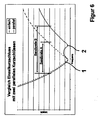
- Fig. 6 are the waveforms of the VSWR versus frequency for a single short-circuit ⁇ / 4 filter and for the in Fig. 4 shown ⁇ / 4 filter assembly shown with a parallel connection of two short-circuiting devices. It can clearly be seen that the bandwidth of a ⁇ / 4 filter assembly as shown in FIG Fig. 4 shown has a greater bandwidth than a ⁇ / 4 filter assembly, which uses only a single short-circuit device. This is because of that the two short-circuit devices 140 and 150 each define a center frequency for the ⁇ / 4 filter, as shown in FIG Fig. 6 can be seen at the marked with 1 and 2 places.
Landscapes
- Physics & Mathematics (AREA)
- Electromagnetism (AREA)
- Filters And Equalizers (AREA)
- Control Of Motors That Do Not Use Commutators (AREA)
- Oscillators With Electromechanical Resonators (AREA)
- Networks Using Active Elements (AREA)
- Semiconductor Lasers (AREA)
- Coupling Device And Connection With Printed Circuit (AREA)
Description
- Die Erfindung betrifft eine abstimmbare λ/4-Filterbaugruppe mit einem signalführenden elektrischen Leiter und einem auf einem Bezugspotential liegenden elektrisch leitfähigen Element, welches insbesondere ein auf Masse liegendes Gehäuse sein kann.
- λ/4-Filter werden beispielsweise in der Hochfrequenztechnik als Bandpässe verwendet. Derartige Filter weisen beispielsweise zwischen einem signalführenden Leiter und einer Masse eine Kurzschlussleitung fester Länge auf. Die Bandbreite des Filters hängt von der Länge des Kurzschlussleiters ab, die die Mittenfrequenz des Filters gemäß der Gleichung f0=c/λ festlegt. Der Bandpass-Charakter eines solchen Filters ergibt sich aus der speziellen Wellencharakteristik bei hohen Frequenzen, da bei hohen Frequenzen der Kurzschluss bei der Mittenfrequenz f0 ausgeblendet wird, so dass Signale mit Frequenzen, die innerhalb einer bestimmten Bandbreite um die Mittenfrequenz verteilt sind, den Leiter passieren können.
- Derartige Filter werden ebenfalls als Überspannungsschutz beispielsweise im Mobilfunk eingesetzt.
- So ist beispielsweise in der
DE 9422 171 U1 ein Überspannungsschutz-Steckverbinder für ein Koaxialkabel beschrieben, welches einen inneren und einen äußeren Leiter aufweist, wobei ein spiralförmiger kurzschließender Blindschwanz fester Länge den Innenleiter mit dem Außenleiter kurzschließt. - Aus der
US PS 6,061,223 ist beispielsweise eine Überspannungs-Schutzeinrichtung bekannt, bei der ein Innenleiter in einem Gehäuse angeordnet ist, die zusammen eine koaxiale Leitung bilden. Ein spiralförmiger Leiter fester Länge dient als Kurzschlusselement, um Energie während eines Überspannungsereignisses zu einer Masseverbindung hin zu übertragen. - Das Dokument
DE 195 20 974 A1 beschreibt einen Überspannungsschutz für HF-Leitungen, mit einem Koaxialleitungsabschnitt aufweisend einen Innenleiter und einen Außenleiter. Der Innenleiter ist über Innenleiterabschnitte mit dem Außenleiter fest verbunden. - Das Dokument
WO 2004/004064 beschreibt eine Blitzstromableiter-Einrichtung mit einem Innenleiter und einem koaxial dazu angeordneten Gehäuse. Ein Paar von zwei Leitungen verbindet den Innenleiter mit dem Gehäuse. - Das Dokument
EP-A-1 772 931 zeigt ein bekanntes Koaxialkabel, wobei Kurzschlusselemente mit einer festen Länge zwischen dem Innenleiter und dem Außenleiter des Koaxialkabels angeordnet sind. - Aus dem Dokument
US-A-2 438 912 geht eine Vorrichtung zur Impedanzanpassung bzw. Impedanzkopplung hervor. Die Vorrichtung weist einen Innenleiter und einen Außenleiter auf, welche mittels isolierender Scheiben voneinander beabstandet sind. - Auch aus dem Dokument
US-A-3 264 584 geht eine Vorrichtung zur Impedanzanpassung bzw. Impedanzkopplung hervor. Die Vorrichtung weist einen Innenleiter und einen Außenleiter auf, welche mittels einer dielektrischen Scheibe elektrisch voneinander isoliert sind. - Das Dokument
DE 15 41 960 A1 beschreibt eine schmalbandige Filteranordnung mit einem äußeren Leiter und einem Innenleiter. Durch den Innenleiter ist ein verschiebbarer Stichleiter gestochen, welcher in einem Rohr liegt. Kurzschlussschieber kontaktieren den Stichleiter mit dem Rohr. - Ein Nachteil der bekannten Filter ist darin zu sehen, dass infolge der festen Kurzschlusslänge die Mittenfrequenz fest vorgegeben ist. Für jedes unterschiedliche Frequenzverhalten muss demzufolge ein separates Filter eingesetzt werden.
- Der vorliegenden Erfindung liegt daher die Aufgabe zugrunde, eine λ/4-Filterbaugruppe zu schaffen, welche universell und für einen variablen Frequenzbereich einsetzbar ist.
- Ein Kerngedanke der Erfindung ist darin zu sehen, ein abstimmbares λ/4-Filter zu schaffen, dessen Frequenzgang veränderbar ist, indem die Länge einer Kurzschlusseinrichtung einstellbar ist.
- Das technische Problem wird durch eine abstimmbare λ/4-Filterbaugruppe gelöst, welche einen signalführenden elektrischen Leiter und ein auf einem Bezugspotential liegendes elektrisch leitfähiges Element aufweist. Zudem ist wenigstens eine Kurzschlusseinrichtung vorgesehen, die den elektrischen Leiter elektrisch kontaktiert. Ferner ist eine elektrische Kopplungseinrichtung vorgesehen, die die Kurzschlusseinrichtung an einer einstellbaren Kontaktstelle mit dem elektrisch leitfähigen Element koppelt, wobei die elektrische Kopplungseinrichtung und die Kurzschlusseinrichtung relativ zueinander bewegbar sind, um so die Länge der Kurzschlusseinrichtung einstellen zu können.
- Die Länge der Kurzschlusseinrichtung ist vorzugsweise kontinuierlich innerhalb eines vorbestimmbaren Längenbereichs einstellbar, wodurch die Mittenfrequenz der abstimmbaren λ/4-Filterbaugruppe ebenfalls kontinuierlich einstellbar ist. Auf diese Weise wird ein λ/4-Filter mit variablem Bandpassverhalten erzielt.
- In zweckmäßiger Weise weist die Kurzschlusseinrichtung einen ersten Kontaktabschnitt, der mit dem elektrischen Leiter verbunden ist, sowie einen zweiten an den ersten Kontaktabschnitt anschließenden Kontaktabschnitt auf, an den die elektrische Kopplungseinrichtung elektrisch angreift.
- Um die Bandbreite des λ/4-Filters verändern zu können, ist eine weitere Kurzschlusseinrichtung vorgesehen, die in der gleichen Ebene wie die erste Kurzschlusseinrichtung liegt. Die weitere Kurzschlusseinrichtung weist einen ersten Kontaktabschnitt, der mit dem elektrischen Leiter verbunden ist, und einen zweiten an den ersten Kontaktabschnitt anschließenden Kontaktabschnitt auf, der an die elektrische Kopplungseinrichtung elektrisch angreift. Die zweiten Kontaktabschnitte der beiden Kurzschlusseinrichtungen bilden jeweils ein Kreissegment-förmiges Leiterelement, welches jeweils im Wesentlichen mit einem Abstand r um den elektrischen Leiter angeordnet ist, wobei die beiden zweiten Kontaktabschnitte im Wesentlichen diametral zueinander angeordnet sind.
- Der Umfang jedes zweiten Kontaktabschnitts ist vorzugsweise kleiner als πr.
- Hierbei ist das elektrische Element wieder ein leitfähiges Gehäuse, welches den Leiter und die Kurzschlusseinrichtung wenigstens teilweise umgibt. Die flexible und leistungsfähige Kopplungseinrichtung weist ein erstes und ein zweites drehbares elektrisch leitfähiges Stellelement mit jeweils einem Kontaktelement auf, wobei die Stellelemente unabhängig voneinander bewegbar sind. Das Kontaktelement des ersten Stellelements greift an einer einstellbaren Kontaktstelle an dem zweiten Kontaktabschnitt der ersten Kurzschlusseinrichtung an, während das Kontaktelement des zweiten Stellelements an einer einstellbaren Kontaktstelle an dem zweiten Kontaktabschnitt der anderen Kurzschlusseinrichtung angreift. In dem Gehäuse ist wenigstens ein Schlitz zum Bewegen der Kontaktelemente mittels der Stellelemente vorgesehen, wobei die Stellelemente an dem Gehäuse anliegen, so dass die Stellelemente und das Gehäuse auf gleichem Potential liegen.
- Bei einer bevorzugten Ausführungsform sind die Kontaktelemente als Schleifkontakte ausgebildet.
- Die Erfindung wird nachfolgend anhand zweier Ausführungsbeispiele in Verbindung mit den beiliegenden Zeichnungen näher erläutert.
Es zeigen: - Fig. 1
- eine abstimmbare λ/4-Filterbaugruppe gemäß der Erfindung im Längsschnitt,
- Fig. 2
- einen Querschnitt der in
Fig. 1 dargestellten λ /4-Filterbaugruppe, - Fig. 3
- eine Seitenansicht der in
Fig. 1 gezeigten λ/4- Filterbaugruppe, - Fig. 4
- eine alternative Ausführungsform einer abstimmbaren λ/4-Filterbaugruppe,
- Fig. 5
- einen Querschnitt der in
Fig. 4 gezeigten λ/4- Filterbaugruppe, und - Fig. 6
- die Kurvenverläufe des VSWR für eine Filterbaugruppe mit einer Kurzschlusseinrichtung bzw. mit zwei Kurzschlusseinrichtungen.
-
Fig. 1 zeigt eine beispielhafte λ/4-Filterbaugruppe 10, deren Mittenfrequenz und somit deren Bandbreite mit Hilfe zweier Kurzschlusseinrichtungen 40 und 50 variabler Länge einstellbar ist. Die schematisch im Längsschnitt dargestellte λ/4-Filterbaugruppe 10 weist einen inneren signalführenden Leiter 20 auf, der an seinen beiden Enden Anschlüsse 25 besitzt. Der elektrische Leiter 20 ist in einem elektrisch leitfähigen Gehäuse 30 vorzugsweise zentral gehalten. Das Gehäuse 30 weist im vorliegenden Beispiel einen kreisförmigen Querschnitt auf, wobei der Durchmesser in der Nähe der beiden Leitungsenden kleiner ist als im mittleren Bereich des elektrischen Leiters 20. An den elektrischen Leiter 20 sind die beiden Kurzschlusseinrichtungen 40 und 50 beispielsweise angelötet, deren Gestaltung inFig. 2 näher dargestellt ist. Um die Mittenfrequenz variieren zu können, ist eine Kopplungseinrichtung 70 vorgesehen, die zwei elektrisch leitfähige Ringe 73 und 75 als Stellelemente aufweist. In dem elektrischen Gehäuse können zwei parallel verlaufende Nuten enthalten sein, in denen die Ringe drehbar geführt werden. An dem Ring 73 ist ein Schleifkontakt 72 angeformt, der die Kurzschlusseinrichtung 40 elektrisch kontaktiert, während am Ring 75 ein Schleifkontakt 77 angeformt ist, welcher die Kurzschlusseinrichtung 50 elektrisch berührt. In dem Gehäuse 30 sind Schlitze vorgesehen, so dass die Schleifkontakte entlang der jeweiligen Kurzschlusseinrichtung mittels der Ringe bewegt werden können. -
Fig. 2 zeigt im Querschnitt die Filterbaugruppe 10 und insbesondere das elektrisch leitfähige Gehäuse 30, welches den elektrischen Leiter 20 und die beiden Kurzschlusseinrichtungen 40 und 50 wenigstens teilweise umgibt. Die Kurzschlusseinrichtung 40 weist einen ersten leiterförmigen Kontaktabschnitt 40a auf, dessen eine Ende an einer vorbestimmten Stelle mit dem elektrischen Leiter 20 elektrisch verbunden ist. Der leiterförmige Kontaktabschnitt 40a erstreckt sich senkrecht von dem elektrischen Leiter 20 weg und weist eine Länge r auf. Am äußeren Ende des Kontaktabschnitts 40a ist ein Kreissegment-förmiger Kontaktabschnitt 40b angeformt. Der elektrische Leiter 20 bildet den Mittelpunkt des Kreissegment-förmigen Kontaktabschnitts 40b, wobei der Krümmungsradius des Kontaktabschnitts 40b im Wesentlichen der Länge r entspricht. Der Schleifkontakt 72 des ringförmigen Stellelements 73 greift an einer Kontaktstelle 80 an dem Kreissegment-förmigen Kontaktabschnitt 40b an. Bei einer Drehung des ringförmigen Stellelements 73 bewegt sich der Schleifkontakt 72 entlang des Kreissegment-förmigen Kontaktabschnitts 40b, wodurch die Kontaktstelle 80 und somit die Länge der Kurzschlusseinrichtung 40 kontinuierlich verändert werden kann. Die Kurzschlussverbindung erstreckt sich vom Leiter 20, über die Konatktabschnitte 40a und 40b, die Kontaktstelle 80, den Schleifkontakt 72, das Stellelement 73 zum elektrisch leitfähigen Gehäuse 30. - Die in der
Fig. 2 dargestellte zweite Kurzschlusseinrichtung 50 ist ähnlich der Kurzschlusseinrichtung 40 aufgebaut. Ein leiterförmiger Kontaktabschnitt 50a ist mit dem elektrischen Leiter 20 an einer Stelle elektrisch verbunden, so dass beide Kurzschlusseinrichtungen 40 und 50 in derselben Ebene liegen. Der leiterförmige Kontaktabschnitt 50a erstreckt sich wiederum senkrecht von dem elektrischen Leiter 20 weg. An seinem äußeren Ende ist ein Kreissegment-förmiger Kontaktabschnitt 50b angeformt. Der leiterförmigen Kontaktabschnitt 50a kann, muss aber nicht, die gleiche Länge r wie der leiterförmige Kontaktabschnitt 40a aufweisen. Wie inFig. 2 gezeigt, weisen beide Kreissegment-förmige Kontaktabschnitte 40b und 50b einen Umfang auf, der kleiner πr ist. Auf diese Weise ergibt sich ein Einstellwinkel für die Stellelemente 73 und 75, der kleiner als 180° ist. Im gezeigten Beispiel kann der Einstellwinkel beispielsweise 150° betragen. - Der Schleifkontakt 77 des Stellelements 75 greift an einer veränderlichen Kontaktstelle 85 an dem Kreissegment-förmigen Kontaktabschnitt 50b an, wodurch die Länge der Kurzschlusseinrichtung 50 einstellbar ist.
- An dieser Stelle sei angemerkt, dass die in
Fig. 2 dargestellten Kreissegment-förmigen Kontaktabschnitte 40b und 50b auch als lineare Kontaktabschnitte ausgebildet sein können, die parallel zum Leiter 20 angeordnet sind. In diesem Fall sind die Stellelemente 73 und 75 nicht als drehbare Ringe ausgebildet, sondern als Stellelemente, die entlang des elektrischen Leiters verschoben werden können, wobei in diesem Fall die Schleifkontakte 72 und 75 an den länglich ausgebildeten Kontaktabschnitten, welche parallel zum elektrischen Leiter verlaufen, angreifen. -
Fig. 3 zeigt eine Draufsicht der inFig. 1 gezeigten Filterbaugruppe 10 mit den beiden ringförmigen Stellelementen 73 und 75, wobei am Gehäuse 30 Markierungen oder Rastpunkte vorhanden sein können, um vordefinierte Bandbreiten für die λ/4-Filterbaugrupe 10 einstellen zu können. -
Fig. 4 zeigt eine alternative λ/4-Filterbaugruppe 100, bei der zwei Kurzschlusseinrichtungen 140 und 150 bezüglich eines elektrischen Leiters 120 axial verschoben zueinander angeordnet sind und somit eine Parallelschaltung bilden. Ein elektrisches Gehäuse 130 ist zumindest teilweise um den elektrischen Leiter 120 und die Kurzschlusseinrichtungen 140 und 150 angeordnet und weist eine ähnliche Form wie das elektrische Gehäuse 30 gemäßFig. 1 auf. Eine Kopplungseinrichtung 170 ist vorgesehen, die bezüglich des Leiters 120 zwei axial zueinander versetzte ringförmige Stellelementen 173 und 125 umfasst. Das ringförmige Stellelement 173 weist einen Schleifkontakt 172 auf, der zur Veränderung der Länge der Kurzschlusseinrichtung 140 an dieser angreift, während ein Schleifkontakt 177 des ringförmigen Stellelements 175 an der Kurzschlusseinrichtung 150 angreift. - In
Fig. 5 ist schematisch der Querschnitt der inFig. 4 gezeigten Filterbaugruppe 100 dargestellt. Das im Querschnitt kreisförmige elektrische Gehäuse 130 umgibt den elektrischen Leiter 130 sowie die mit dem Leiter 130 elektrisch verbundene Kurzschlusseinrichtungen 140 und 150. InFig. 5 ist lediglich die Kurzschlusseinrichtung 140 dargestellt. Die Kurzschlusseinrichtung 150 ist ähnlich der Kurzschlusseinrichtung 140 geformt und wird von dieser in der gezeigten Darstellung verdeckt. Die Kurzschlusseinrichtung 140 weist einen leiterförmigen Kontaktabschnitt 140a auf, der an einer Kontaktstelle des elektrischen Leiters 120 beispielsweise angelötet ist. Der leiterförmige Kontaktabschnitt 140a erstreckt sich senkrecht vom elektrischen Leiter 120 weg. Die Länge des Kontaktabschnittes 140a betrage r. Am äußeren Ende des leiterförmigen Kontaktabschnittes 140a schließt sich ein kreisförmiger Kontaktabschnitt 140b an, der im Wesentlichen im Abstand r konzentrisch um den elektrischen Leiter 120 verläuft. Der Umfang des kreisförmigen Kontaktabschnittes 140b ist kleiner als 2πr, so dass sich ein Einstellwinkel für das Stellelement 173 ergibt, der kleiner als 360° aber größer als der Einstellwinkel der inFig. 1 und 2 gezeigten Stellelemente ist. - Wie in
Fig. 5 gezeigt, greift der Schleifkontakt 172 des Stellelementes 173 an einer Kontaktstelle 180 an dem kreisförmigen Kontaktabschnitt 140b an, wodurch eine elektrische Verbindung zwischen dem elektrischen Leiter 120 und dem Gehäuse 130 gebildet wird, die über den Kontaktabschnitt 140a, den kreisförmigen Kontaktabschnitt 140b, den Schleifenkontakt 172 des elektrisch leitfähigen Stellelement 173 und dem Gehäuse 130 gebildet wird. In axialem Abstand dazu ist das Stellelement 175 und die Kurzschlusseinrichtung 150 angeordnet. Stellelement 173 und Stellelement 175 können unabhängig voneinander bewegt werden, so dass die Bandbreite der λ/4-Filterbaugruppe 100 variabel einstellbar ist. - In
Fig. 6 sind die Kurvenverläufe des VSWR (Voltage Standing Wave Ratio) über der Frequenz für ein λ/4-Filter mit einer einzigen Kurzschlusseinrichtung und für die inFig. 4 gezeigte λ/4-Filterbaugruppe mit einer Parallelschaltung zweier Kurzschlusseinrichtungen dargestellt. Es ist deutlich zu sehen, dass die Bandbreite einer λ/4-Filterbaugruppe, wie sie inFig. 4 gezeigt ist, eine größere Bandbreite aufweist, als eine λ/4-Filterbaugruppe, welche nur eine einzige Kurzschlusseinrichtung verwendet. Dies liegt daran, dass die beiden Kurzschlusseinrichtungen 140 und 150 jeweils eine Mittenfrequenz für das λ/4-Filter festlegen, wie dies inFig. 6 an den mit 1 und 2 markierten Stellen erkennbar ist.
Claims (3)
- Abstimmbare λ/4-Filterbaugruppe (10; 100) mit einem signalführenden elektrischen Leiter (20; 120), einem auf einem Bezugspotential liegenden elektrisch leitfähigen Element (30; 130),
wenigstens einer Kurzschlusseinrichtung (40; 140), die den elektrischen Leiter (20; 120) elektrisch kontaktiert,
einer elektrischen Kopplungseinrichtung (70; 170), die die Kurzschlusseinrichtung (40; 140) an einer einstellbaren Kontaktstelle (80; 180) mit dem elektrisch leitfähigen Element (30; 130) koppelt, wobei die elektrische Kopplungseinrichtung (70; 170) und die Kurzschlusseinrichtung (40; 140) relativ zueinander bewegbar sind, um die Länge der Kurzschlusseinrichtung (40; 140) einstellen zu können wobei
die Kurzschlusseinrichtung (40; 140) einen ersten Kontaktabschnitt (40a; 140a), der mit dem elektrischen Leiter (20; 120) verbunden ist, und einen zweiten, an den ersten Kontaktabschnitt (40a; 140a) anschließenden Kontaktabschnitt (40b; 140b) aufweist, an den die elektrische Kopplungseinrichtung (70; 170) elektrisch angreift, wobei
eine weitere Kurzschlusseinrichtung (50), die einen ersten Kontaktabschnitt (50a), der mit dem elektrischen Leiter (20) verbunden ist, und einen zweiten, an den ersten Kontaktabschnitt (50a) anschließenden Kontaktabschnitt (50b) aufweist, an den die elektrische Kopplungseinrichtung (70) elektrisch angreift, wobei die beiden Kurzschlusseinrichtungen in der gleichen Ebene liegen, wobei das elektrische Element ein Gehäuse (30) ist, welches den Leiter (20) und die Kurzschlusseinrichtungen (40, 50) wenigstens teilweise umgibt, und wobei
die Kopplungseinrichtung (70) ein erstes und ein zweites drehbares, elektrisch leitfähiges Stellelement (73, 75) mit jeweils einem Kontaktelement (72, 77) aufweist, wobei das Kontaktelement (72) des ersten Stellelements an einer einstellbaren Kontaktstelle (80) an dem zweiten Kontaktabschnitt (40b) der ersten Kurzschlusseinrichtung (40) und das Kontaktelement (77) des zweiten Stellelements (75) an einer einstellbaren Kontaktstelle (85) an dem zweiten Kontaktabschnitt (50b) der anderen Kurzschlusseinrichtung (50) angreifen, und wobei in dem Gehäuse (30) wenigstens ein Schlitz zum Durchführen der Kontaktelemente (72, 77) vorgesehen ist und die Stellelemente an dem Gehäuse (30) anliegen, wobei
die zweiten Kontaktabschnitte (40b, 50b) der beiden Kurzschlusseinrichtungen (40, 50) jeweils ein Kreissegment-förmiges Leiterelement bilden, welches jeweils in einem Abstand r um den elektrischen Leiter (20) angeordnet ist, und wobei
die zweiten Kontaktabschnitte (40b, 50b) im Wesentlichen diametral zueinander angeordnet sind und die Stellelemente unabhängig voneinander bewegbar sind. - Abstimmbare λ/4-Filterbaugruppe nach Anspruch 1,
dadurch gekennzeichnet, dass
der Umfang jedes zweiten Kontaktabschnitts (40b, 50b) kleiner als πr ist. - Abstimmbare λ/4-Filterbaugruppe nach einem der Ansprüche 1 oder 2,
dadurch gekennzeichnet, dass
die Kontaktelemente (72, 77; 172, 177) Schleifkontakte sind.
Applications Claiming Priority (1)
| Application Number | Priority Date | Filing Date | Title |
|---|---|---|---|
| DE102007030157A DE102007030157A1 (de) | 2007-06-27 | 2007-06-27 | Abstimmbare λ/4 Filterbaugruppe |
Publications (2)
| Publication Number | Publication Date |
|---|---|
| EP2009732A1 EP2009732A1 (de) | 2008-12-31 |
| EP2009732B1 true EP2009732B1 (de) | 2011-03-23 |
Family
ID=39765233
Family Applications (1)
| Application Number | Title | Priority Date | Filing Date |
|---|---|---|---|
| EP08010853A Not-in-force EP2009732B1 (de) | 2007-06-27 | 2008-06-14 | Abstimmbare Lambda-Viertel Filterbaugruppe |
Country Status (4)
| Country | Link |
|---|---|
| US (1) | US7826194B2 (de) |
| EP (1) | EP2009732B1 (de) |
| AT (1) | ATE503286T1 (de) |
| DE (2) | DE102007030157A1 (de) |
Families Citing this family (2)
| Publication number | Priority date | Publication date | Assignee | Title |
|---|---|---|---|---|
| US8456789B2 (en) * | 2010-12-15 | 2013-06-04 | Andrew Llc | Tunable coaxial surge arrestor |
| US10790564B2 (en) * | 2016-07-18 | 2020-09-29 | Commscope Italy, S.R.L. | Tubular in-line filters that are suitable for cellular applications and related methods |
Family Cites Families (13)
| Publication number | Priority date | Publication date | Assignee | Title |
|---|---|---|---|---|
| DE87341C (de) | ||||
| US2438912A (en) | 1942-06-29 | 1948-04-06 | Sperry Corp | Impedance transformer |
| US3264584A (en) | 1961-11-15 | 1966-08-02 | Bell Telephone Labor Inc | Adjustable impedance matching transformers |
| DE1541960A1 (de) | 1967-02-01 | 1970-11-26 | Philips Patentverwaltung | Schmalbandige Filteranordnung |
| JPS58225586A (ja) * | 1982-06-23 | 1983-12-27 | ヒロセ電機株式会社 | 同軸型避雷構造 |
| EP0671063B1 (de) * | 1993-10-07 | 1999-01-07 | Andrew A.G. | Verbinder mit schutz gegen überspannung |
| DE9422171U1 (de) | 1993-10-07 | 1998-09-17 | Andrew AG, Bachenbulach, Zürich | Überspannungsschutz-Steckverbindung |
| DE19520974A1 (de) | 1995-06-08 | 1996-12-12 | Spinner Gmbh Elektrotech | Überspannungsschutz für HF-Leitungen |
| US6061223A (en) | 1997-10-14 | 2000-05-09 | Polyphaser Corporation | Surge suppressor device |
| DE19936869C1 (de) | 1999-08-05 | 2001-03-08 | Spinner Gmbh Elektrotech | Koaxialer Überspannungsableiter |
| WO2002103875A1 (en) * | 2001-06-15 | 2002-12-27 | Kauffman George M | Protective device |
| ES2239552T3 (es) * | 2002-06-26 | 2008-02-16 | HUBER & SUHNER AG | Dispositivo de filtro antiparasito y descargador de corriente de rayo. |
| US7324318B2 (en) | 2005-10-07 | 2008-01-29 | Andrew Corporation | Multiple planar inductor coaxial surge suppressor |
-
2007
- 2007-06-27 DE DE102007030157A patent/DE102007030157A1/de not_active Withdrawn
-
2008
- 2008-06-14 AT AT08010853T patent/ATE503286T1/de active
- 2008-06-14 EP EP08010853A patent/EP2009732B1/de not_active Not-in-force
- 2008-06-14 DE DE502008002925T patent/DE502008002925D1/de active Active
- 2008-06-25 US US12/146,028 patent/US7826194B2/en not_active Expired - Fee Related
Also Published As
| Publication number | Publication date |
|---|---|
| ATE503286T1 (de) | 2011-04-15 |
| EP2009732A1 (de) | 2008-12-31 |
| US20090002103A1 (en) | 2009-01-01 |
| DE502008002925D1 (de) | 2011-05-05 |
| DE102007030157A1 (de) | 2009-01-08 |
| US7826194B2 (en) | 2010-11-02 |
Similar Documents
| Publication | Publication Date | Title |
|---|---|---|
| DE69415790T2 (de) | Verbinder mit schutz gegen überspannung | |
| AT393762B (de) | Als wendelantenne ausgebildete uhf-sendeund/oder empfangsantenne | |
| EP3635814B1 (de) | Dual-polarisierter kreuzdipol und antennenanordnung mit zwei solchen dual-polarisierten kreuzdipolen | |
| EP2656435B1 (de) | Abstimmbares hochfrequenzfilter | |
| DE60107313T2 (de) | Überspannungsschutz für Breitband-Anpassungszweig | |
| DE69501782T2 (de) | Überspannungsableiter für koaxialübertragungsleitung | |
| EP2735052B1 (de) | Ungerichteter hf-leistungsteiler | |
| EP1516390B1 (de) | Störschutzfilter- und blitzstromableiter-einrichtung | |
| DE2656729C3 (de) | Breitbanddipolantenne | |
| DE837404C (de) | Verbindungsstueck zum Verbinden eines Erdsymmetrischen Stromkreises mit einem erdunsymmetrischen | |
| EP2374182B1 (de) | Filternanordnung | |
| DE69625054T2 (de) | Antennenanordnung | |
| EP0855756B1 (de) | EMP-Ableiter | |
| DE4005654C2 (de) | ||
| DE19512003A1 (de) | Antenne für die Ausstrahlung und/oder den Empfang elektromagnetischer Signale, insbesondere Ultrahochfrequenzen, und Vorrichtung, welche eine derartige Antenne verwendet | |
| DE202019101043U1 (de) | Phasenschiebermodulanordnung zum Einsatz in einer Mobilfunkantenne | |
| EP3837741B1 (de) | Kabelanordnung | |
| DE10241431B4 (de) | Überspannungsschutzsystem für eine koaxiale Übertragungsleitung | |
| EP2009732A1 (de) | Abstimmbare Viertelwellen-Filterbaugruppe | |
| WO2006029868A1 (de) | Hochfrequenzfilter | |
| DE2908255C2 (de) | Y-Zirkulator | |
| DE19920980A1 (de) | Speise- oder Auskoppelvorrichtung für Koaxialleitung, insbesondere für Mehrfach-Koaxialleitung | |
| EP1885016B1 (de) | Überspannungsschutz für eine Koaxialleitung | |
| DE9421069U1 (de) | Überspannungsschutz-Steckverbindung | |
| DE10212365C1 (de) | Koaxialverbinder mit Überspannungsschutz |
Legal Events
| Date | Code | Title | Description |
|---|---|---|---|
| PUAI | Public reference made under article 153(3) epc to a published international application that has entered the european phase |
Free format text: ORIGINAL CODE: 0009012 |
|
| AK | Designated contracting states |
Kind code of ref document: A1 Designated state(s): AT BE BG CH CY CZ DE DK EE ES FI FR GB GR HR HU IE IS IT LI LT LU LV MC MT NL NO PL PT RO SE SI SK TR |
|
| AX | Request for extension of the european patent |
Extension state: AL BA MK RS |
|
| RTI1 | Title (correction) |
Free format text: ADJUSTABLE LAMBDA-QUARTER FILTER ASSEMBLY |
|
| 17P | Request for examination filed |
Effective date: 20090630 |
|
| 17Q | First examination report despatched |
Effective date: 20090730 |
|
| AKX | Designation fees paid |
Designated state(s): AT BE BG CH CY CZ DE DK EE ES FI FR GB GR HR HU IE IS IT LI LT LU LV MC MT NL NO PL PT RO SE SI SK TR |
|
| GRAP | Despatch of communication of intention to grant a patent |
Free format text: ORIGINAL CODE: EPIDOSNIGR1 |
|
| GRAS | Grant fee paid |
Free format text: ORIGINAL CODE: EPIDOSNIGR3 |
|
| GRAA | (expected) grant |
Free format text: ORIGINAL CODE: 0009210 |
|
| AK | Designated contracting states |
Kind code of ref document: B1 Designated state(s): AT BE BG CH CY CZ DE DK EE ES FI FR GB GR HR HU IE IS IT LI LT LU LV MC MT NL NO PL PT RO SE SI SK TR |
|
| REG | Reference to a national code |
Ref country code: GB Ref legal event code: FG4D Free format text: NOT ENGLISH |
|
| REG | Reference to a national code |
Ref country code: CH Ref legal event code: EP |
|
| REG | Reference to a national code |
Ref country code: IE Ref legal event code: FG4D |
|
| REF | Corresponds to: |
Ref document number: 502008002925 Country of ref document: DE Date of ref document: 20110505 Kind code of ref document: P |
|
| REG | Reference to a national code |
Ref country code: DE Ref legal event code: R096 Ref document number: 502008002925 Country of ref document: DE Effective date: 20110505 |
|
| REG | Reference to a national code |
Ref country code: SE Ref legal event code: TRGR |
|
| REG | Reference to a national code |
Ref country code: NL Ref legal event code: VDEP Effective date: 20110323 |
|
| PG25 | Lapsed in a contracting state [announced via postgrant information from national office to epo] |
Ref country code: LV Free format text: LAPSE BECAUSE OF FAILURE TO SUBMIT A TRANSLATION OF THE DESCRIPTION OR TO PAY THE FEE WITHIN THE PRESCRIBED TIME-LIMIT Effective date: 20110323 Ref country code: GR Free format text: LAPSE BECAUSE OF FAILURE TO SUBMIT A TRANSLATION OF THE DESCRIPTION OR TO PAY THE FEE WITHIN THE PRESCRIBED TIME-LIMIT Effective date: 20110624 Ref country code: HR Free format text: LAPSE BECAUSE OF FAILURE TO SUBMIT A TRANSLATION OF THE DESCRIPTION OR TO PAY THE FEE WITHIN THE PRESCRIBED TIME-LIMIT Effective date: 20110323 Ref country code: LT Free format text: LAPSE BECAUSE OF FAILURE TO SUBMIT A TRANSLATION OF THE DESCRIPTION OR TO PAY THE FEE WITHIN THE PRESCRIBED TIME-LIMIT Effective date: 20110323 |
|
| LTIE | Lt: invalidation of european patent or patent extension |
Effective date: 20110323 |
|
| PG25 | Lapsed in a contracting state [announced via postgrant information from national office to epo] |
Ref country code: NO Free format text: LAPSE BECAUSE OF FAILURE TO SUBMIT A TRANSLATION OF THE DESCRIPTION OR TO PAY THE FEE WITHIN THE PRESCRIBED TIME-LIMIT Effective date: 20110623 Ref country code: SI Free format text: LAPSE BECAUSE OF FAILURE TO SUBMIT A TRANSLATION OF THE DESCRIPTION OR TO PAY THE FEE WITHIN THE PRESCRIBED TIME-LIMIT Effective date: 20110323 Ref country code: BG Free format text: LAPSE BECAUSE OF FAILURE TO SUBMIT A TRANSLATION OF THE DESCRIPTION OR TO PAY THE FEE WITHIN THE PRESCRIBED TIME-LIMIT Effective date: 20110623 Ref country code: CY Free format text: LAPSE BECAUSE OF FAILURE TO SUBMIT A TRANSLATION OF THE DESCRIPTION OR TO PAY THE FEE WITHIN THE PRESCRIBED TIME-LIMIT Effective date: 20110323 |
|
| REG | Reference to a national code |
Ref country code: IE Ref legal event code: FD4D |
|
| PG25 | Lapsed in a contracting state [announced via postgrant information from national office to epo] |
Ref country code: EE Free format text: LAPSE BECAUSE OF FAILURE TO SUBMIT A TRANSLATION OF THE DESCRIPTION OR TO PAY THE FEE WITHIN THE PRESCRIBED TIME-LIMIT Effective date: 20110323 Ref country code: PT Free format text: LAPSE BECAUSE OF FAILURE TO SUBMIT A TRANSLATION OF THE DESCRIPTION OR TO PAY THE FEE WITHIN THE PRESCRIBED TIME-LIMIT Effective date: 20110725 |
|
| PG25 | Lapsed in a contracting state [announced via postgrant information from national office to epo] |
Ref country code: RO Free format text: LAPSE BECAUSE OF FAILURE TO SUBMIT A TRANSLATION OF THE DESCRIPTION OR TO PAY THE FEE WITHIN THE PRESCRIBED TIME-LIMIT Effective date: 20110323 Ref country code: IS Free format text: LAPSE BECAUSE OF FAILURE TO SUBMIT A TRANSLATION OF THE DESCRIPTION OR TO PAY THE FEE WITHIN THE PRESCRIBED TIME-LIMIT Effective date: 20110723 Ref country code: CZ Free format text: LAPSE BECAUSE OF FAILURE TO SUBMIT A TRANSLATION OF THE DESCRIPTION OR TO PAY THE FEE WITHIN THE PRESCRIBED TIME-LIMIT Effective date: 20110323 Ref country code: SK Free format text: LAPSE BECAUSE OF FAILURE TO SUBMIT A TRANSLATION OF THE DESCRIPTION OR TO PAY THE FEE WITHIN THE PRESCRIBED TIME-LIMIT Effective date: 20110323 Ref country code: ES Free format text: LAPSE BECAUSE OF FAILURE TO SUBMIT A TRANSLATION OF THE DESCRIPTION OR TO PAY THE FEE WITHIN THE PRESCRIBED TIME-LIMIT Effective date: 20110704 |
|
| PG25 | Lapsed in a contracting state [announced via postgrant information from national office to epo] |
Ref country code: MT Free format text: LAPSE BECAUSE OF FAILURE TO SUBMIT A TRANSLATION OF THE DESCRIPTION OR TO PAY THE FEE WITHIN THE PRESCRIBED TIME-LIMIT Effective date: 20110323 Ref country code: NL Free format text: LAPSE BECAUSE OF FAILURE TO SUBMIT A TRANSLATION OF THE DESCRIPTION OR TO PAY THE FEE WITHIN THE PRESCRIBED TIME-LIMIT Effective date: 20110323 |
|
| BERE | Be: lapsed |
Owner name: PHOENIX CONTACT G.M.B.H. & CO. KG Effective date: 20110630 |
|
| PLBE | No opposition filed within time limit |
Free format text: ORIGINAL CODE: 0009261 |
|
| STAA | Information on the status of an ep patent application or granted ep patent |
Free format text: STATUS: NO OPPOSITION FILED WITHIN TIME LIMIT |
|
| PG25 | Lapsed in a contracting state [announced via postgrant information from national office to epo] |
Ref country code: IE Free format text: LAPSE BECAUSE OF FAILURE TO SUBMIT A TRANSLATION OF THE DESCRIPTION OR TO PAY THE FEE WITHIN THE PRESCRIBED TIME-LIMIT Effective date: 20110323 |
|
| 26N | No opposition filed |
Effective date: 20111227 |
|
| PG25 | Lapsed in a contracting state [announced via postgrant information from national office to epo] |
Ref country code: PL Free format text: LAPSE BECAUSE OF FAILURE TO SUBMIT A TRANSLATION OF THE DESCRIPTION OR TO PAY THE FEE WITHIN THE PRESCRIBED TIME-LIMIT Effective date: 20110323 Ref country code: DK Free format text: LAPSE BECAUSE OF FAILURE TO SUBMIT A TRANSLATION OF THE DESCRIPTION OR TO PAY THE FEE WITHIN THE PRESCRIBED TIME-LIMIT Effective date: 20110323 |
|
| REG | Reference to a national code |
Ref country code: FR Ref legal event code: ST Effective date: 20120229 |
|
| PG25 | Lapsed in a contracting state [announced via postgrant information from national office to epo] |
Ref country code: BE Free format text: LAPSE BECAUSE OF NON-PAYMENT OF DUE FEES Effective date: 20110630 |
|
| REG | Reference to a national code |
Ref country code: DE Ref legal event code: R097 Ref document number: 502008002925 Country of ref document: DE Effective date: 20111227 |
|
| PG25 | Lapsed in a contracting state [announced via postgrant information from national office to epo] |
Ref country code: FR Free format text: LAPSE BECAUSE OF NON-PAYMENT OF DUE FEES Effective date: 20110630 |
|
| PG25 | Lapsed in a contracting state [announced via postgrant information from national office to epo] |
Ref country code: IT Free format text: LAPSE BECAUSE OF FAILURE TO SUBMIT A TRANSLATION OF THE DESCRIPTION OR TO PAY THE FEE WITHIN THE PRESCRIBED TIME-LIMIT Effective date: 20110323 |
|
| REG | Reference to a national code |
Ref country code: CH Ref legal event code: PL |
|
| REG | Reference to a national code |
Ref country code: CH Ref legal event code: PL |
|
| GBPC | Gb: european patent ceased through non-payment of renewal fee |
Effective date: 20120614 |
|
| PG25 | Lapsed in a contracting state [announced via postgrant information from national office to epo] |
Ref country code: LI Free format text: LAPSE BECAUSE OF NON-PAYMENT OF DUE FEES Effective date: 20120630 Ref country code: MC Free format text: LAPSE BECAUSE OF NON-PAYMENT OF DUE FEES Effective date: 20110630 Ref country code: CH Free format text: LAPSE BECAUSE OF NON-PAYMENT OF DUE FEES Effective date: 20120630 Ref country code: GB Free format text: LAPSE BECAUSE OF NON-PAYMENT OF DUE FEES Effective date: 20120614 |
|
| PG25 | Lapsed in a contracting state [announced via postgrant information from national office to epo] |
Ref country code: LU Free format text: LAPSE BECAUSE OF NON-PAYMENT OF DUE FEES Effective date: 20110614 |
|
| PG25 | Lapsed in a contracting state [announced via postgrant information from national office to epo] |
Ref country code: TR Free format text: LAPSE BECAUSE OF FAILURE TO SUBMIT A TRANSLATION OF THE DESCRIPTION OR TO PAY THE FEE WITHIN THE PRESCRIBED TIME-LIMIT Effective date: 20110323 |
|
| PG25 | Lapsed in a contracting state [announced via postgrant information from national office to epo] |
Ref country code: HU Free format text: LAPSE BECAUSE OF FAILURE TO SUBMIT A TRANSLATION OF THE DESCRIPTION OR TO PAY THE FEE WITHIN THE PRESCRIBED TIME-LIMIT Effective date: 20110323 |
|
| REG | Reference to a national code |
Ref country code: AT Ref legal event code: MM01 Ref document number: 503286 Country of ref document: AT Kind code of ref document: T Effective date: 20130614 |
|
| PGFP | Annual fee paid to national office [announced via postgrant information from national office to epo] |
Ref country code: SE Payment date: 20140623 Year of fee payment: 7 Ref country code: FI Payment date: 20140626 Year of fee payment: 7 |
|
| PG25 | Lapsed in a contracting state [announced via postgrant information from national office to epo] |
Ref country code: AT Free format text: LAPSE BECAUSE OF NON-PAYMENT OF DUE FEES Effective date: 20130614 |
|
| PGFP | Annual fee paid to national office [announced via postgrant information from national office to epo] |
Ref country code: DE Payment date: 20150728 Year of fee payment: 8 |
|
| PG25 | Lapsed in a contracting state [announced via postgrant information from national office to epo] |
Ref country code: FI Free format text: LAPSE BECAUSE OF NON-PAYMENT OF DUE FEES Effective date: 20150614 |
|
| REG | Reference to a national code |
Ref country code: SE Ref legal event code: EUG |
|
| PG25 | Lapsed in a contracting state [announced via postgrant information from national office to epo] |
Ref country code: SE Free format text: LAPSE BECAUSE OF NON-PAYMENT OF DUE FEES Effective date: 20150615 |
|
| REG | Reference to a national code |
Ref country code: DE Ref legal event code: R119 Ref document number: 502008002925 Country of ref document: DE |
|
| PG25 | Lapsed in a contracting state [announced via postgrant information from national office to epo] |
Ref country code: DE Free format text: LAPSE BECAUSE OF NON-PAYMENT OF DUE FEES Effective date: 20170103 |