EP2009746A9 - Koaxialer Winkelstecker mit innerem Leitungsübergang und Herstellungsverfahren - Google Patents
Koaxialer Winkelstecker mit innerem Leitungsübergang und Herstellungsverfahren Download PDFInfo
- Publication number
- EP2009746A9 EP2009746A9 EP08005761A EP08005761A EP2009746A9 EP 2009746 A9 EP2009746 A9 EP 2009746A9 EP 08005761 A EP08005761 A EP 08005761A EP 08005761 A EP08005761 A EP 08005761A EP 2009746 A9 EP2009746 A9 EP 2009746A9
- Authority
- EP
- European Patent Office
- Prior art keywords
- inner conductor
- connector
- primary
- interface
- transition
- Prior art date
- Legal status (The legal status is an assumption and is not a legal conclusion. Google has not performed a legal analysis and makes no representation as to the accuracy of the status listed.)
- Granted
Links
- 239000004020 conductor Substances 0.000 title claims abstract description 63
- 230000007704 transition Effects 0.000 title claims abstract description 24
- 238000000034 method Methods 0.000 title claims description 17
- 238000004519 manufacturing process Methods 0.000 title claims description 9
- 230000008878 coupling Effects 0.000 claims description 17
- 238000010168 coupling process Methods 0.000 claims description 17
- 238000005859 coupling reaction Methods 0.000 claims description 17
- 229910052751 metal Inorganic materials 0.000 claims description 11
- 239000002184 metal Substances 0.000 claims description 11
- 239000012212 insulator Substances 0.000 claims description 10
- 238000001746 injection moulding Methods 0.000 claims description 6
- 230000000717 retained effect Effects 0.000 claims description 6
- 239000000463 material Substances 0.000 description 6
- 238000003754 machining Methods 0.000 description 4
- 229910000679 solder Inorganic materials 0.000 description 4
- 229910000861 Mg alloy Inorganic materials 0.000 description 3
- 230000008901 benefit Effects 0.000 description 3
- 238000005516 engineering process Methods 0.000 description 3
- 150000002739 metals Chemical class 0.000 description 3
- 238000007789 sealing Methods 0.000 description 3
- 239000007787 solid Substances 0.000 description 3
- 230000009974 thixotropic effect Effects 0.000 description 3
- 239000000853 adhesive Substances 0.000 description 2
- 230000001070 adhesive effect Effects 0.000 description 2
- 238000005266 casting Methods 0.000 description 2
- 238000002347 injection Methods 0.000 description 2
- 239000007924 injection Substances 0.000 description 2
- 238000009434 installation Methods 0.000 description 2
- 229910001092 metal group alloy Inorganic materials 0.000 description 2
- 238000012986 modification Methods 0.000 description 2
- 230000004048 modification Effects 0.000 description 2
- 238000000465 moulding Methods 0.000 description 2
- 230000008569 process Effects 0.000 description 2
- 239000002699 waste material Substances 0.000 description 2
- 239000011230 binding agent Substances 0.000 description 1
- 230000005540 biological transmission Effects 0.000 description 1
- 230000000295 complement effect Effects 0.000 description 1
- 230000007812 deficiency Effects 0.000 description 1
- 230000000694 effects Effects 0.000 description 1
- 239000000284 extract Substances 0.000 description 1
- 230000001965 increasing effect Effects 0.000 description 1
- 238000003780 insertion Methods 0.000 description 1
- 230000037431 insertion Effects 0.000 description 1
- 230000002452 interceptive effect Effects 0.000 description 1
- 230000013011 mating Effects 0.000 description 1
- 239000007769 metal material Substances 0.000 description 1
- 238000005555 metalworking Methods 0.000 description 1
- 229920005596 polymer binder Polymers 0.000 description 1
- 239000002491 polymer binding agent Substances 0.000 description 1
- 239000000843 powder Substances 0.000 description 1
- 238000003908 quality control method Methods 0.000 description 1
- 230000009467 reduction Effects 0.000 description 1
- 239000002904 solvent Substances 0.000 description 1
- 239000001993 wax Substances 0.000 description 1
Images


Classifications
-
- H—ELECTRICITY
- H01—ELECTRIC ELEMENTS
- H01R—ELECTRICALLY-CONDUCTIVE CONNECTIONS; STRUCTURAL ASSOCIATIONS OF A PLURALITY OF MUTUALLY-INSULATED ELECTRICAL CONNECTING ELEMENTS; COUPLING DEVICES; CURRENT COLLECTORS
- H01R24/00—Two-part coupling devices, or either of their cooperating parts, characterised by their overall structure
- H01R24/38—Two-part coupling devices, or either of their cooperating parts, characterised by their overall structure having concentrically or coaxially arranged contacts
- H01R24/40—Two-part coupling devices, or either of their cooperating parts, characterised by their overall structure having concentrically or coaxially arranged contacts specially adapted for high frequency
- H01R24/54—Intermediate parts, e.g. adapters, splitters or elbows
-
- H—ELECTRICITY
- H01—ELECTRIC ELEMENTS
- H01R—ELECTRICALLY-CONDUCTIVE CONNECTIONS; STRUCTURAL ASSOCIATIONS OF A PLURALITY OF MUTUALLY-INSULATED ELECTRICAL CONNECTING ELEMENTS; COUPLING DEVICES; CURRENT COLLECTORS
- H01R9/00—Structural associations of a plurality of mutually-insulated electrical connecting elements, e.g. terminal strips or terminal blocks; Terminals or binding posts mounted upon a base or in a case; Bases therefor
- H01R9/03—Connectors arranged to contact a plurality of the conductors of a multiconductor cable, e.g. tapping connections
- H01R9/05—Connectors arranged to contact a plurality of the conductors of a multiconductor cable, e.g. tapping connections for coaxial cables
-
- H—ELECTRICITY
- H01—ELECTRIC ELEMENTS
- H01R—ELECTRICALLY-CONDUCTIVE CONNECTIONS; STRUCTURAL ASSOCIATIONS OF A PLURALITY OF MUTUALLY-INSULATED ELECTRICAL CONNECTING ELEMENTS; COUPLING DEVICES; CURRENT COLLECTORS
- H01R13/00—Details of coupling devices of the kinds covered by groups H01R12/70 or H01R24/00 - H01R33/00
- H01R13/46—Bases; Cases
- H01R13/52—Dustproof, splashproof, drip-proof, waterproof, or flameproof cases
- H01R13/5202—Sealing means between parts of housing or between housing part and a wall, e.g. sealing rings
-
- H—ELECTRICITY
- H01—ELECTRIC ELEMENTS
- H01R—ELECTRICALLY-CONDUCTIVE CONNECTIONS; STRUCTURAL ASSOCIATIONS OF A PLURALITY OF MUTUALLY-INSULATED ELECTRICAL CONNECTING ELEMENTS; COUPLING DEVICES; CURRENT COLLECTORS
- H01R13/00—Details of coupling devices of the kinds covered by groups H01R12/70 or H01R24/00 - H01R33/00
- H01R13/62—Means for facilitating engagement or disengagement of coupling parts or for holding them in engagement
- H01R13/622—Screw-ring or screw-casing
-
- H—ELECTRICITY
- H01—ELECTRIC ELEMENTS
- H01R—ELECTRICALLY-CONDUCTIVE CONNECTIONS; STRUCTURAL ASSOCIATIONS OF A PLURALITY OF MUTUALLY-INSULATED ELECTRICAL CONNECTING ELEMENTS; COUPLING DEVICES; CURRENT COLLECTORS
- H01R24/00—Two-part coupling devices, or either of their cooperating parts, characterised by their overall structure
- H01R24/38—Two-part coupling devices, or either of their cooperating parts, characterised by their overall structure having concentrically or coaxially arranged contacts
- H01R24/40—Two-part coupling devices, or either of their cooperating parts, characterised by their overall structure having concentrically or coaxially arranged contacts specially adapted for high frequency
- H01R24/42—Two-part coupling devices, or either of their cooperating parts, characterised by their overall structure having concentrically or coaxially arranged contacts specially adapted for high frequency comprising impedance matching means or electrical components, e.g. filters or switches
- H01R24/44—Two-part coupling devices, or either of their cooperating parts, characterised by their overall structure having concentrically or coaxially arranged contacts specially adapted for high frequency comprising impedance matching means or electrical components, e.g. filters or switches comprising impedance matching means
-
- H—ELECTRICITY
- H01—ELECTRIC ELEMENTS
- H01R—ELECTRICALLY-CONDUCTIVE CONNECTIONS; STRUCTURAL ASSOCIATIONS OF A PLURALITY OF MUTUALLY-INSULATED ELECTRICAL CONNECTING ELEMENTS; COUPLING DEVICES; CURRENT COLLECTORS
- H01R9/00—Structural associations of a plurality of mutually-insulated electrical connecting elements, e.g. terminal strips or terminal blocks; Terminals or binding posts mounted upon a base or in a case; Bases therefor
- H01R9/03—Connectors arranged to contact a plurality of the conductors of a multiconductor cable, e.g. tapping connections
- H01R9/05—Connectors arranged to contact a plurality of the conductors of a multiconductor cable, e.g. tapping connections for coaxial cables
- H01R9/0521—Connection to outer conductor by action of a nut
-
- H—ELECTRICITY
- H01—ELECTRIC ELEMENTS
- H01R—ELECTRICALLY-CONDUCTIVE CONNECTIONS; STRUCTURAL ASSOCIATIONS OF A PLURALITY OF MUTUALLY-INSULATED ELECTRICAL CONNECTING ELEMENTS; COUPLING DEVICES; CURRENT COLLECTORS
- H01R9/00—Structural associations of a plurality of mutually-insulated electrical connecting elements, e.g. terminal strips or terminal blocks; Terminals or binding posts mounted upon a base or in a case; Bases therefor
- H01R9/16—Fastening of connecting parts to base or case; Insulating connecting parts from base or case
- H01R9/18—Fastening by means of screw or nut
-
- H—ELECTRICITY
- H01—ELECTRIC ELEMENTS
- H01R—ELECTRICALLY-CONDUCTIVE CONNECTIONS; STRUCTURAL ASSOCIATIONS OF A PLURALITY OF MUTUALLY-INSULATED ELECTRICAL CONNECTING ELEMENTS; COUPLING DEVICES; CURRENT COLLECTORS
- H01R2103/00—Two poles
Definitions
- the invention relates to connectors for coaxial cable. More particularly the invention relates to a right angle coaxial connector with improved electrical performance and a cost effective method of precision manufacture.
- Angled coaxial cable connectors are useful for connecting to an RF device when a cable to device connection with the cable extending normal to the device is undesirable, such as a cable connection to a rack mounted device and or a device located close to an interfering surface such as a wall.
- the right angle transition of the inner conductor necessary to form a right angle coaxial connector introduces several problems.
- the right angle transition makes it difficult to insert the inner conductor within the surrounding body, unless the body is formed in multiple pieces, has access covers and or, for example, a soldered connection is made at the transition point once the inner conductor is inserted from one end, which greatly complicates assembly.
- the transition introduces an impedance discontinuity into the coaxial transmission line to which the connector is attached.
- Both smooth larger radius bends and block type sharp corner bends introduce a measurable impedance discontinuity.
- the inner conductor element may be small in size and relatively fragile, significantly complicating cost effective manufacture with high levels of precision.
- an angled coaxial cable connector 1 is demonstrated with a primary side 3 standardized 7-16 DIN connector primary interface 5 and a secondary side 7 with an annular corrugated solid outer conductor coaxial cable 43 secondary interface 9.
- the connector 1 is demonstrated as a right angle.
- any desired angle, connection interface and or coaxial cable interfaces may be applied to either or both of the primary and secondary sides 3, 7.
- the connector 1 has a unitary generally cylindrical inner conductor 11 mounted coaxial within a bore 13 extending between the primary side 3 and the secondary side 7 of an outer body 15.
- the inner conductor 11 has a first end 17 on a longitudinal axis having a transition 19 to a second end 21 on a secondary axis normal to the primary longitudinal axis.
- Unitary as used herein defines the inner conductor 11 as formed as a single integral element, not an assembly joined together via mechanical fasteners, soldered or via adhesive from separately fabricated elements.
- Generally cylindrical as used herein means that, except for the areas of the transition 19, the first end 17 and the second end 21 (depending upon the interfaces selected), the inner conductor 11 has a circular cross section taken along the primary longitudinal axis and the secondary axis, respectively.
- an outer side 23 of the transition 19 is formed with a planar back angle surface 25, best shown for example in figures 3-5 .
- the planar back angle surface 25 may be arranged symmetrical with both the longitudinal axis and the secondary axis, at one half of the angle between the primary longitudinal axis and the secondary axis, in this case forty-five degrees to both the primary longitudinal axis and to the secondary axis, respectively.
- An inner side 27 of the transition may be formed with an arc radius or alternatively, a right angle intersection 29.
- the planar back angle surface 25 extends across the width of the inner conductor 11 presenting an angled "reflective surface" to the direction of signal flow between the longitudinal axis and the secondary axis complementary to the desired angle of the connector, having increasing effects on the inner conductor 11 with respect to reduction of impedance discontinuity and generation of intermodulation distortion as the operating frequency increases.
- the first and second ends 17, 21 of the inner conductor 11 are configured for the desired primary and secondary interfaces 5, 9.
- the first end 17 is demonstrated as a pin 31 for the 7/16 DIN connector interface.
- the second end 21 has a coupling surface 33 in the form of threads 35.
- the threads 35 of the coupling surface 33 enable easy attachment of a range of different inner conductor interface(s) 37, here demonstrated as a spring basket 39 for securely contacting a solid center conductor 41 of an annular corrugated solid outer conductor coaxial cable 43.
- the outer body 15 is formed with a bore 13 between primary and secondary sides 3, 7.
- a primary interface mount 45 is formed in the primary side 3 of the body15, for example, In the form of an angular groove 47 open the primary side 3, preferably coaxial with the bore 13.
- a primary interface 5 may be press fit within the annular groove 47, the primary interface 5 carrying an insulator 51 which positions the inner conductor 11 coaxial within the bore 13, retained with respect to the insulator 51 by inner conductor shoulder(s) 53 (see figures 2 ).
- the insulator 51 may be retained, for example, between the primary side 3 and an interface shoulder 55.
- a sealing gasket 57 such as an o-ring, may be applied between the insulator 51 and the primary interface 5 to environmentally seal the connector 1, even when unconnected to another connector or device.
- the secondary interface 9 is demonstrated as a spring finger nut 59 against outer conductor clamp surface 61 coaxial cable interface 63 attached to the outer body 15 via a secondary interface mount 64 here demonstrated as an integral threaded shoulder 65.
- An insulator 51 supporting the inner conductor interfaces 37 seats against a body shoulder 67, retained by an inward projecting lip of the secondary interface 9.
- Sealing gasket(s) 57 may be applied at the connections between the outer body 15 and the body shoulder 65, between the spring finger nut 59 and the coaxial cable interface 63 and between the outer conductor 67 and the spring finger nut 59 to environmentally seal the connection.
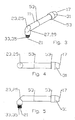
- Figure 9 common element notations as described herein above, demonstrates an alternative embodiment, here having an angle of forty five degrees.
- the planar back angle surface 25 is applied symmetrical with both the longitudinal axis and the secondary axis, at one half the angle between the primary longitudinal axis and the secondary axis.
- the planar back angle surface 25 extends across less than the width of the inner conductor 11 presenting an angled "reflective surface" to the direction of signal flow for only a portion of the conductor cross section.
- impedance discontinuity effects are reduced even where the reflective surface covers less than the full inner conductor 11 cross section.
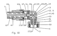
- FIGs 10 and 11 Alternatives for the coupling surface 33 and further variations of the second interface 9 for specific coaxial cables are demonstrated in Figures 10 and 11 , common element notations as described herein above.
- the inner conductor interface 37 is coupled to the inner conductor 11 at the coupling surface 33 via a spring basket 39 rather than threads.
- Figure 11 demonstrates a direct solder connection of the center conductor 41 to a coupling surface 33 formed as a cavity, eliminating the need for the inner conducor interface 37. Access to the solder area is provided by a solder port 69.
- the coupling surface 33 can be any connection means, for example, a pin into socket with annular or cantilever snap fit.
- a conductive adhesive may also be applied to the selected inner conductor interface 37 interconnection with the coupling surface 33.
- An angled connector 1 according to the invention may be manufactured using a combination of different techniques each selected to minimize overall costs while generating the different components with a desired level of precision.
- the elements that are generally concentric, including the relatively small inner conductor interface spring basket 37, may be manufactured via machining or molding depending upon the materials desired.
- the outer body 15 is relatively simple to mold or machine, having minimal features.
- the specific geometry of the inner conductor 11 may be cost effectively formed with high precision via Metal Injection Molding (MIM) or Thixoforming, to reduce the quality control, cost and time requirements associated with high tolerance mechanical machining of a small non-concentric electrical component.
- MIM Metal Injection Molding
- Thixoforming to reduce the quality control, cost and time requirements associated with high tolerance mechanical machining of a small non-concentric electrical component.
- MIM also known as powder injection molding
- powder injection molding is a net-shape process for producing solid metal parts that combines the design freedom of plastic injection molding with material properties near that of wrought metals.
- MIM is capable of producing an almost limitless array of highly complex geometries in many different metals and metal alloys.
- Design and economic limitations of traditional metalworking technologies, such as machining and casting, can be overcome by MIM.
- finely granulated metal material is uniformly mixed with a wax or polymer binder and injection molded.
- a "green" molded part is then extracted from the mold.
- a de-binding step extracts the majority of binder from the green part via application of low temperature and or a solvent.
- the de-bound green part is then sintered at high temperature wherein the de-bound part is proportionally shrunk to the final target size, concentrating the metal density and strength characteristics to close to that of a casting made from the same material by conventional means.
- MIM manufacturing technologies may be applied to form the precision shapes of inner conductors described herein using a range of metals and or metal alloys. Because of the minimal waste inherent in the MIM manufacturing process, although the superior electro-mechanical properties of a metal is realized, the material cost is minimized because extremely low waste occurs relative to metal machining.
- Thixoforming is another highly advantageous method of forming the inner conductor via thixotropic magnesium alloy metal injection molding technology.
- a magnesium alloy is heated until it reaches a thixotropic state and is then injection molded, similar to plastic injection molding techniques.
- an inner conductor according to the invention may be cost effectively fabricated to high levels of manufacturing tolerance and in high volumes.
- The, for example, magnesium alloys used in thixotropic metal molding have suitable rigidity characteristics and also have the benefit of being light in weight.
- the invention provides a cost effective right angle coaxial connector 1 with improved electrical performance despite having a minimum number of separate components. Also, materials cost and the complexity of required assembly operations are reduced. Installation of the connector onto the cable may be reliably achieved with time requirements and assembly operations similar those of a conventional straight body coaxial connector.
Landscapes
- Coupling Device And Connection With Printed Circuit (AREA)
- Manufacturing Of Electrical Connectors (AREA)
Applications Claiming Priority (1)
| Application Number | Priority Date | Filing Date | Title |
|---|---|---|---|
| US11/765,869 US7419403B1 (en) | 2007-06-20 | 2007-06-20 | Angled coaxial connector with inner conductor transition and method of manufacture |
Publications (4)
| Publication Number | Publication Date |
|---|---|
| EP2009746A2 EP2009746A2 (de) | 2008-12-31 |
| EP2009746A9 true EP2009746A9 (de) | 2009-03-25 |
| EP2009746A3 EP2009746A3 (de) | 2011-11-09 |
| EP2009746B1 EP2009746B1 (de) | 2013-03-20 |
Family
ID=39718358
Family Applications (1)
| Application Number | Title | Priority Date | Filing Date |
|---|---|---|---|
| EP08005761A Not-in-force EP2009746B1 (de) | 2007-06-20 | 2008-03-27 | Koaxialer Winkelstecker mit innerem Leitungsübergang und Herstellungsverfahren |
Country Status (7)
| Country | Link |
|---|---|
| US (1) | US7419403B1 (de) |
| EP (1) | EP2009746B1 (de) |
| JP (1) | JP2009004376A (de) |
| KR (1) | KR20080112107A (de) |
| CN (1) | CN101330182A (de) |
| BR (1) | BRPI0803016A2 (de) |
| CA (1) | CA2631078A1 (de) |
Families Citing this family (34)
| Publication number | Priority date | Publication date | Assignee | Title |
|---|---|---|---|---|
| US8826972B2 (en) * | 2005-07-28 | 2014-09-09 | Intelliserv, Llc | Platform for electrically coupling a component to a downhole transmission line |
| US7607942B1 (en) * | 2008-08-14 | 2009-10-27 | Andrew Llc | Multi-shot coaxial connector and method of manufacture |
| US20110003507A1 (en) * | 2008-08-14 | 2011-01-06 | Andrew Llc | Multi-shot Connector Assembly and Method of Manufacture |
| GB2469023B (en) * | 2009-03-30 | 2013-01-02 | Tyco Electronics Ltd Uk | Coaxial connector and method of assembling one |
| CN101888048B (zh) * | 2009-05-12 | 2013-02-27 | 深圳日海通讯技术股份有限公司 | 一种同轴电缆连接器 |
| US20100304608A1 (en) * | 2009-05-26 | 2010-12-02 | Jan Michael Clausen | Angled Coaxial Junction |
| US8047872B2 (en) * | 2009-07-22 | 2011-11-01 | Corning Gilbert Inc. | Coaxial angle connector and related method |
| CN102044815B (zh) * | 2009-10-22 | 2014-04-02 | 西安金波科技有限责任公司 | Sma射频同轴连接器的加工方法 |
| CN101826692A (zh) * | 2010-05-10 | 2010-09-08 | 苏州市吴通通讯器材有限公司 | 一种移动通信转接器 |
| CN101888049B (zh) * | 2010-06-21 | 2012-06-20 | 贵州航天电器股份有限公司 | 一种弯式射频三同轴电连接器 |
| US8668504B2 (en) | 2011-07-05 | 2014-03-11 | Dave Smith Chevrolet Oldsmobile Pontiac Cadillac, Inc. | Threadless light bulb socket |
| DE102012201123B3 (de) * | 2012-01-26 | 2013-03-21 | Lisa Dräxlmaier GmbH | Gewinkelter Hochvolt-Stecker |
| US9054471B2 (en) * | 2012-02-03 | 2015-06-09 | Megaphase, Llc | Coaxial angled adapter |
| US9793660B2 (en) * | 2012-03-19 | 2017-10-17 | Holland Electronics, Llc | Shielded coaxial connector |
| US20160336697A1 (en) * | 2015-01-20 | 2016-11-17 | Spinner Gmbh | Hf coaxial cable with angular plug connection, and a method for producing same |
| US8992250B1 (en) * | 2013-03-15 | 2015-03-31 | Megaphase, Llc | Clockable cable adapter |
| WO2014148205A1 (ja) * | 2013-03-21 | 2014-09-25 | 日本電気株式会社 | マイクロ波屋外無線装置 |
| US9478929B2 (en) | 2014-06-23 | 2016-10-25 | Ken Smith | Light bulb receptacles and light bulb sockets |
| CN105990744B (zh) * | 2015-01-30 | 2019-06-07 | 康普技术有限责任公司 | 包括同轴电缆和直角弯头同轴连接器的组件及其制造方法 |
| CN104638433A (zh) * | 2015-02-15 | 2015-05-20 | 苏州东威连接器电子有限公司 | 一种弯角连接器 |
| US9941616B2 (en) | 2015-02-24 | 2018-04-10 | Thomas & Betts International Llc | Multi-piece jacket for separable connectors |
| US20160284442A1 (en) * | 2015-03-24 | 2016-09-29 | Fujitsu Limited | Coaxial cable |
| US9691525B2 (en) | 2015-03-24 | 2017-06-27 | Fujitsu Limited | Coaxial cable |
| CN104993259B (zh) * | 2015-05-27 | 2017-08-29 | 中国工程物理研究院化工材料研究所 | 小型低电感高压圆形电连接器 |
| WO2018057333A1 (en) * | 2016-09-20 | 2018-03-29 | Commscope Technologies Llc | Right angle coaxial connector assembly |
| JP6814080B2 (ja) * | 2017-03-23 | 2021-01-13 | ホシデン株式会社 | L型インナー端子、そのl型インナー端子を含むl型同軸コネクタ及びそのl型同軸コネクタの製造方法 |
| CN107394542A (zh) * | 2017-08-30 | 2017-11-24 | 陕西益华电气股份有限公司 | 一种配接电缆的弯式射频同轴连接器 |
| CN108054569B (zh) * | 2017-12-26 | 2019-12-17 | 中国人民解放军海军工程大学 | 一种大水深大电流穿舱密封组件 |
| US11456566B2 (en) * | 2020-03-05 | 2022-09-27 | Applied Optoelectronics, Inc. | Coaxial connector seizure assembly with integrated mechanical stop and a hybrid fiber-coaxial (HFC) module implementing same |
| CN112736543A (zh) * | 2020-12-08 | 2021-04-30 | 北京无线电计量测试研究所 | 一种直角弯型射频电缆连接器 |
| KR102569196B1 (ko) * | 2021-02-22 | 2023-08-22 | 계림금속 주식회사 | 금속분말 사출성형을 이용한 전기자동차용 구리 커넥터의 제조방법 |
| KR200496820Y1 (ko) * | 2021-05-10 | 2023-05-08 | (주) 라투스 | 알에프 커넥터 |
| CN114323444A (zh) * | 2021-12-07 | 2022-04-12 | 北京无线电计量测试研究所 | 一种耐高温密封腔测试装置和配置方法 |
| CN115986476A (zh) * | 2023-01-13 | 2023-04-18 | 中航富士达科技股份有限公司 | 一种mil-dtl-5015标准弯式圆柱形连接器 |
Family Cites Families (26)
| Publication number | Priority date | Publication date | Assignee | Title |
|---|---|---|---|---|
| BE416412A (de) | 1935-07-08 | |||
| US2165961A (en) | 1935-10-22 | 1939-07-11 | Emi Ltd | High frequency signaling system |
| US2530064A (en) | 1944-04-18 | 1950-11-14 | Clarence W Jones | Bent coaxial transmission line |
| US2952823A (en) | 1956-03-26 | 1960-09-13 | Boeing Co | High-frequency coaxial transmission line elbow fittings |
| JPS58155786U (ja) * | 1982-04-13 | 1983-10-18 | ヒロセ電機株式会社 | L字形同軸コネクタ |
| US4900258A (en) | 1989-06-12 | 1990-02-13 | Amp Incorporated | Multi-port coaxial printed circuit board connector |
| US5037329A (en) | 1990-09-27 | 1991-08-06 | Gte Products Corporation | Angular connector for a shielded coaxial cable |
| US5322453A (en) | 1992-11-25 | 1994-06-21 | M/A-Com Omni Spectra, Inc. | RF connector jack and plug assembly |
| US6471545B1 (en) | 1993-05-14 | 2002-10-29 | The Whitaker Corporation | Coaxial connector for coaxial cable having a corrugated outer conductor |
| US6540558B1 (en) | 1995-07-03 | 2003-04-01 | Berg Technology, Inc. | Connector, preferably a right angle connector, with integrated PCB assembly |
| US6126482A (en) | 1997-10-31 | 2000-10-03 | Thomas & Betts International, Inc. | Right angle coaxial cable connector |
| FR2781934B1 (fr) * | 1998-07-31 | 2000-10-06 | Radiall Sa | Element de connecteur coaxial comportant un raccord pour relier le conducteur central d'un cable coaxial au contact central de l'element de connecteur |
| JP2000340303A (ja) * | 1999-05-27 | 2000-12-08 | Orient Micro Wave:Kk | 金属ハウジング、同軸コネクタおよびその製造方法 |
| JP2002151218A (ja) * | 2000-11-14 | 2002-05-24 | Sumitomo Electric Ind Ltd | 同軸管エルボ |
| US6361348B1 (en) | 2001-01-15 | 2002-03-26 | Tyco Electronics Corporation | Right angle, snap on coaxial electrical connector |
| US6478618B2 (en) * | 2001-04-06 | 2002-11-12 | Shen-Chia Wong | High retention coaxial connector |
| JP2002334754A (ja) * | 2001-05-09 | 2002-11-22 | Orient Micro Wave:Kk | L型同軸コネクタおよびその製造方法 |
| US6454601B1 (en) * | 2001-06-27 | 2002-09-24 | Andrew Corporation | Connector for coaxial cables |
| JP3500135B2 (ja) * | 2001-07-24 | 2004-02-23 | 古河電気工業株式会社 | 同軸給電線と同軸エルボとの接続部構造 |
| US6719586B2 (en) | 2002-02-12 | 2004-04-13 | Tyco Electronics Corporation | Electrical connector with anti-tip feature to prevent tipping during assembly |
| US6821150B2 (en) | 2002-11-22 | 2004-11-23 | Tyco Electronics Corporation | Connector assembly having dielectric cover |
| US6817899B1 (en) | 2003-04-09 | 2004-11-16 | Yazaki North America, Inc. | Angled connector for coaxial cable |
| JP2006221968A (ja) * | 2005-02-10 | 2006-08-24 | Hitachi Cable Ltd | 高周波同軸ケーブル用コネクタ |
| US7070440B1 (en) | 2005-06-03 | 2006-07-04 | Yazaki North America, Inc. | Coaxial cable insulation displacement connector |
| US7121883B1 (en) * | 2005-06-06 | 2006-10-17 | John Mezzalingua Associates, Inc. | Coax connector having steering insulator |
| US7217154B2 (en) * | 2005-10-19 | 2007-05-15 | Andrew Corporation | Connector with outer conductor axial compression connection and method of manufacture |
-
2007
- 2007-06-20 US US11/765,869 patent/US7419403B1/en active Active
-
2008
- 2008-03-27 EP EP08005761A patent/EP2009746B1/de not_active Not-in-force
- 2008-05-09 CA CA002631078A patent/CA2631078A1/en not_active Abandoned
- 2008-05-30 KR KR1020080050869A patent/KR20080112107A/ko not_active Ceased
- 2008-06-11 JP JP2008153561A patent/JP2009004376A/ja active Pending
- 2008-06-17 CN CNA2008101256715A patent/CN101330182A/zh active Pending
- 2008-06-20 BR BRPI0803016-2A patent/BRPI0803016A2/pt not_active IP Right Cessation
Also Published As
| Publication number | Publication date |
|---|---|
| EP2009746A3 (de) | 2011-11-09 |
| JP2009004376A (ja) | 2009-01-08 |
| CN101330182A (zh) | 2008-12-24 |
| EP2009746B1 (de) | 2013-03-20 |
| BRPI0803016A2 (pt) | 2010-01-26 |
| CA2631078A1 (en) | 2008-12-20 |
| KR20080112107A (ko) | 2008-12-24 |
| EP2009746A2 (de) | 2008-12-31 |
| US7419403B1 (en) | 2008-09-02 |
Similar Documents
| Publication | Publication Date | Title |
|---|---|---|
| EP2009746B1 (de) | Koaxialer Winkelstecker mit innerem Leitungsübergang und Herstellungsverfahren | |
| EP2917981B1 (de) | Hf-geschirmte kapazitiv gekoppelte steckverbinderanordnung und herstellungsverfahren | |
| US7275957B1 (en) | Axial compression electrical connector for annular corrugated coaxial cable | |
| US7217154B2 (en) | Connector with outer conductor axial compression connection and method of manufacture | |
| US7803018B1 (en) | Inner conductor end contacting coaxial connector and inner conductor adapter kit | |
| US8636522B2 (en) | Coaxial connector | |
| US7044785B2 (en) | Connector and coaxial cable with outer conductor cylindrical section axial compression connection | |
| US5074809A (en) | Ultraminiature high-frequency connection interface | |
| US8622762B2 (en) | Blind mate capacitively coupled connector | |
| EP2117084B1 (de) | Elektrische Verbundstoffsteckverbinderanordnung | |
| US7520779B2 (en) | 7-16 coaxial flanged receptacles | |
| US7837502B2 (en) | Multi-shot coaxial connector and method of manufacture | |
| EP2432081A1 (de) | Multishot-Steckeranordnung und Herstellungsverfahren | |
| EP2615699A1 (de) | HF-Verbinder | |
| EP2028726A2 (de) | Hohler innerer Leiterkontakt für einen Koaxialkabelstecker | |
| EP3300535B1 (de) | Hf koaxialsteckverbinder mit niedriger passiver intermodulation | |
| US20130065420A1 (en) | Connector With Capacitively Coupled Connector Interface | |
| US20140308846A1 (en) | Electrical connector having resilient latches | |
| EP2777098A1 (de) | Blindsteckbarer kapazitiv gekoppelter verbinder | |
| CN203275457U (zh) | 一种接插装置 | |
| WO2013071204A1 (en) | Connector with capacitively coupled connector interface | |
| US20130157508A1 (en) | Coaxial connector with coupling nut | |
| CN212085374U (zh) | 一种射频同轴连接器插座 | |
| EP1860745A2 (de) | Wolfram-Kurzschlussplatte und Herstellungsverfahren dafür |
Legal Events
| Date | Code | Title | Description |
|---|---|---|---|
| PUAI | Public reference made under article 153(3) epc to a published international application that has entered the european phase |
Free format text: ORIGINAL CODE: 0009012 |
|
| AK | Designated contracting states |
Kind code of ref document: A2 Designated state(s): AT BE BG CH CY CZ DE DK EE ES FI FR GB GR HR HU IE IS IT LI LT LU LV MC MT NL NO PL PT RO SE SI SK TR |
|
| AX | Request for extension of the european patent |
Extension state: AL BA MK RS |
|
| PUAL | Search report despatched |
Free format text: ORIGINAL CODE: 0009013 |
|
| AK | Designated contracting states |
Kind code of ref document: A3 Designated state(s): AT BE BG CH CY CZ DE DK EE ES FI FR GB GR HR HU IE IS IT LI LT LU LV MC MT NL NO PL PT RO SE SI SK TR |
|
| AX | Request for extension of the european patent |
Extension state: AL BA MK RS |
|
| RIC1 | Information provided on ipc code assigned before grant |
Ipc: H01R 9/05 20060101AFI20110930BHEP |
|
| 17P | Request for examination filed |
Effective date: 20120111 |
|
| AKX | Designation fees paid |
Designated state(s): AT BE BG CH CY CZ DE DK EE ES FI FR GB GR HR HU IE IS IT LI LT LU LV MC MT NL NO PL PT RO SE SI SK TR |
|
| GRAP | Despatch of communication of intention to grant a patent |
Free format text: ORIGINAL CODE: EPIDOSNIGR1 |
|
| GRAS | Grant fee paid |
Free format text: ORIGINAL CODE: EPIDOSNIGR3 |
|
| GRAA | (expected) grant |
Free format text: ORIGINAL CODE: 0009210 |
|
| AK | Designated contracting states |
Kind code of ref document: B1 Designated state(s): AT BE BG CH CY CZ DE DK EE ES FI FR GB GR HR HU IE IS IT LI LT LU LV MC MT NL NO PL PT RO SE SI SK TR |
|
| REG | Reference to a national code |
Ref country code: GB Ref legal event code: FG4D |
|
| REG | Reference to a national code |
Ref country code: CH Ref legal event code: EP |
|
| REG | Reference to a national code |
Ref country code: IE Ref legal event code: FG4D |
|
| REG | Reference to a national code |
Ref country code: AT Ref legal event code: REF Ref document number: 602571 Country of ref document: AT Kind code of ref document: T Effective date: 20130415 |
|
| REG | Reference to a national code |
Ref country code: DE Ref legal event code: R096 Ref document number: 602008022966 Country of ref document: DE Effective date: 20130508 |
|
| PG25 | Lapsed in a contracting state [announced via postgrant information from national office to epo] |
Ref country code: SE Free format text: LAPSE BECAUSE OF FAILURE TO SUBMIT A TRANSLATION OF THE DESCRIPTION OR TO PAY THE FEE WITHIN THE PRESCRIBED TIME-LIMIT Effective date: 20130320 Ref country code: LT Free format text: LAPSE BECAUSE OF FAILURE TO SUBMIT A TRANSLATION OF THE DESCRIPTION OR TO PAY THE FEE WITHIN THE PRESCRIBED TIME-LIMIT Effective date: 20130320 Ref country code: BG Free format text: LAPSE BECAUSE OF FAILURE TO SUBMIT A TRANSLATION OF THE DESCRIPTION OR TO PAY THE FEE WITHIN THE PRESCRIBED TIME-LIMIT Effective date: 20130620 Ref country code: NO Free format text: LAPSE BECAUSE OF FAILURE TO SUBMIT A TRANSLATION OF THE DESCRIPTION OR TO PAY THE FEE WITHIN THE PRESCRIBED TIME-LIMIT Effective date: 20130620 Ref country code: ES Free format text: LAPSE BECAUSE OF FAILURE TO SUBMIT A TRANSLATION OF THE DESCRIPTION OR TO PAY THE FEE WITHIN THE PRESCRIBED TIME-LIMIT Effective date: 20130701 |
|
| REG | Reference to a national code |
Ref country code: AT Ref legal event code: MK05 Ref document number: 602571 Country of ref document: AT Kind code of ref document: T Effective date: 20130320 |
|
| REG | Reference to a national code |
Ref country code: LT Ref legal event code: MG4D |
|
| PG25 | Lapsed in a contracting state [announced via postgrant information from national office to epo] |
Ref country code: LV Free format text: LAPSE BECAUSE OF FAILURE TO SUBMIT A TRANSLATION OF THE DESCRIPTION OR TO PAY THE FEE WITHIN THE PRESCRIBED TIME-LIMIT Effective date: 20130320 Ref country code: GR Free format text: LAPSE BECAUSE OF FAILURE TO SUBMIT A TRANSLATION OF THE DESCRIPTION OR TO PAY THE FEE WITHIN THE PRESCRIBED TIME-LIMIT Effective date: 20130621 Ref country code: SI Free format text: LAPSE BECAUSE OF FAILURE TO SUBMIT A TRANSLATION OF THE DESCRIPTION OR TO PAY THE FEE WITHIN THE PRESCRIBED TIME-LIMIT Effective date: 20130320 Ref country code: FI Free format text: LAPSE BECAUSE OF FAILURE TO SUBMIT A TRANSLATION OF THE DESCRIPTION OR TO PAY THE FEE WITHIN THE PRESCRIBED TIME-LIMIT Effective date: 20130320 |
|
| REG | Reference to a national code |
Ref country code: NL Ref legal event code: VDEP Effective date: 20130320 |
|
| PG25 | Lapsed in a contracting state [announced via postgrant information from national office to epo] |
Ref country code: HR Free format text: LAPSE BECAUSE OF FAILURE TO SUBMIT A TRANSLATION OF THE DESCRIPTION OR TO PAY THE FEE WITHIN THE PRESCRIBED TIME-LIMIT Effective date: 20130320 Ref country code: BE Free format text: LAPSE BECAUSE OF FAILURE TO SUBMIT A TRANSLATION OF THE DESCRIPTION OR TO PAY THE FEE WITHIN THE PRESCRIBED TIME-LIMIT Effective date: 20130320 |
|
| PG25 | Lapsed in a contracting state [announced via postgrant information from national office to epo] |
Ref country code: CZ Free format text: LAPSE BECAUSE OF FAILURE TO SUBMIT A TRANSLATION OF THE DESCRIPTION OR TO PAY THE FEE WITHIN THE PRESCRIBED TIME-LIMIT Effective date: 20130320 Ref country code: IS Free format text: LAPSE BECAUSE OF FAILURE TO SUBMIT A TRANSLATION OF THE DESCRIPTION OR TO PAY THE FEE WITHIN THE PRESCRIBED TIME-LIMIT Effective date: 20130720 Ref country code: PT Free format text: LAPSE BECAUSE OF FAILURE TO SUBMIT A TRANSLATION OF THE DESCRIPTION OR TO PAY THE FEE WITHIN THE PRESCRIBED TIME-LIMIT Effective date: 20130722 Ref country code: MC Free format text: LAPSE BECAUSE OF NON-PAYMENT OF DUE FEES Effective date: 20130331 Ref country code: AT Free format text: LAPSE BECAUSE OF FAILURE TO SUBMIT A TRANSLATION OF THE DESCRIPTION OR TO PAY THE FEE WITHIN THE PRESCRIBED TIME-LIMIT Effective date: 20130320 Ref country code: NL Free format text: LAPSE BECAUSE OF FAILURE TO SUBMIT A TRANSLATION OF THE DESCRIPTION OR TO PAY THE FEE WITHIN THE PRESCRIBED TIME-LIMIT Effective date: 20130320 Ref country code: SK Free format text: LAPSE BECAUSE OF FAILURE TO SUBMIT A TRANSLATION OF THE DESCRIPTION OR TO PAY THE FEE WITHIN THE PRESCRIBED TIME-LIMIT Effective date: 20130320 Ref country code: EE Free format text: LAPSE BECAUSE OF FAILURE TO SUBMIT A TRANSLATION OF THE DESCRIPTION OR TO PAY THE FEE WITHIN THE PRESCRIBED TIME-LIMIT Effective date: 20130320 Ref country code: RO Free format text: LAPSE BECAUSE OF FAILURE TO SUBMIT A TRANSLATION OF THE DESCRIPTION OR TO PAY THE FEE WITHIN THE PRESCRIBED TIME-LIMIT Effective date: 20130320 |
|
| REG | Reference to a national code |
Ref country code: CH Ref legal event code: PL |
|
| PG25 | Lapsed in a contracting state [announced via postgrant information from national office to epo] |
Ref country code: PL Free format text: LAPSE BECAUSE OF FAILURE TO SUBMIT A TRANSLATION OF THE DESCRIPTION OR TO PAY THE FEE WITHIN THE PRESCRIBED TIME-LIMIT Effective date: 20130320 Ref country code: CY Free format text: LAPSE BECAUSE OF FAILURE TO SUBMIT A TRANSLATION OF THE DESCRIPTION OR TO PAY THE FEE WITHIN THE PRESCRIBED TIME-LIMIT Effective date: 20130320 |
|
| REG | Reference to a national code |
Ref country code: IE Ref legal event code: MM4A |
|
| REG | Reference to a national code |
Ref country code: DE Ref legal event code: R119 Ref document number: 602008022966 Country of ref document: DE Effective date: 20131001 |
|
| PLBE | No opposition filed within time limit |
Free format text: ORIGINAL CODE: 0009261 |
|
| STAA | Information on the status of an ep patent application or granted ep patent |
Free format text: STATUS: NO OPPOSITION FILED WITHIN TIME LIMIT |
|
| PG25 | Lapsed in a contracting state [announced via postgrant information from national office to epo] |
Ref country code: LI Free format text: LAPSE BECAUSE OF NON-PAYMENT OF DUE FEES Effective date: 20130331 Ref country code: DE Free format text: LAPSE BECAUSE OF NON-PAYMENT OF DUE FEES Effective date: 20131001 Ref country code: IE Free format text: LAPSE BECAUSE OF NON-PAYMENT OF DUE FEES Effective date: 20130327 Ref country code: DK Free format text: LAPSE BECAUSE OF FAILURE TO SUBMIT A TRANSLATION OF THE DESCRIPTION OR TO PAY THE FEE WITHIN THE PRESCRIBED TIME-LIMIT Effective date: 20130320 Ref country code: CH Free format text: LAPSE BECAUSE OF NON-PAYMENT OF DUE FEES Effective date: 20130331 |
|
| 26N | No opposition filed |
Effective date: 20140102 |
|
| GBPC | Gb: european patent ceased through non-payment of renewal fee |
Effective date: 20130620 |
|
| PG25 | Lapsed in a contracting state [announced via postgrant information from national office to epo] |
Ref country code: IT Free format text: LAPSE BECAUSE OF FAILURE TO SUBMIT A TRANSLATION OF THE DESCRIPTION OR TO PAY THE FEE WITHIN THE PRESCRIBED TIME-LIMIT Effective date: 20130320 |
|
| PG25 | Lapsed in a contracting state [announced via postgrant information from national office to epo] |
Ref country code: GB Free format text: LAPSE BECAUSE OF NON-PAYMENT OF DUE FEES Effective date: 20130620 |
|
| PG25 | Lapsed in a contracting state [announced via postgrant information from national office to epo] |
Ref country code: MT Free format text: LAPSE BECAUSE OF FAILURE TO SUBMIT A TRANSLATION OF THE DESCRIPTION OR TO PAY THE FEE WITHIN THE PRESCRIBED TIME-LIMIT Effective date: 20130320 |
|
| PG25 | Lapsed in a contracting state [announced via postgrant information from national office to epo] |
Ref country code: TR Free format text: LAPSE BECAUSE OF FAILURE TO SUBMIT A TRANSLATION OF THE DESCRIPTION OR TO PAY THE FEE WITHIN THE PRESCRIBED TIME-LIMIT Effective date: 20130320 |
|
| PG25 | Lapsed in a contracting state [announced via postgrant information from national office to epo] |
Ref country code: HU Free format text: LAPSE BECAUSE OF FAILURE TO SUBMIT A TRANSLATION OF THE DESCRIPTION OR TO PAY THE FEE WITHIN THE PRESCRIBED TIME-LIMIT; INVALID AB INITIO Effective date: 20080327 Ref country code: LU Free format text: LAPSE BECAUSE OF NON-PAYMENT OF DUE FEES Effective date: 20130327 |
|
| PG25 | Lapsed in a contracting state [announced via postgrant information from national office to epo] |
Ref country code: FR Free format text: LAPSE BECAUSE OF NON-PAYMENT OF DUE FEES Effective date: 20130331 |