EP2009808A1 - Kommunikation über Trägerstrom an die zentralen Schalttafeln - Google Patents
Kommunikation über Trägerstrom an die zentralen Schalttafeln Download PDFInfo
- Publication number
- EP2009808A1 EP2009808A1 EP08354034A EP08354034A EP2009808A1 EP 2009808 A1 EP2009808 A1 EP 2009808A1 EP 08354034 A EP08354034 A EP 08354034A EP 08354034 A EP08354034 A EP 08354034A EP 2009808 A1 EP2009808 A1 EP 2009808A1
- Authority
- EP
- European Patent Office
- Prior art keywords
- line
- impedance
- interfaces
- carrier current
- cpl
- Prior art date
- Legal status (The legal status is an assumption and is not a legal conclusion. Google has not performed a legal analysis and makes no representation as to the accuracy of the status listed.)
- Granted
Links
Images
Classifications
-
- H—ELECTRICITY
- H04—ELECTRIC COMMUNICATION TECHNIQUE
- H04B—TRANSMISSION
- H04B3/00—Line transmission systems
- H04B3/54—Systems for transmission via power distribution lines
-
- H—ELECTRICITY
- H04—ELECTRIC COMMUNICATION TECHNIQUE
- H04B—TRANSMISSION
- H04B2203/00—Indexing scheme relating to line transmission systems
- H04B2203/54—Aspects of powerline communications not already covered by H04B3/54 and its subgroups
- H04B2203/5404—Methods of transmitting or receiving signals via power distribution lines
- H04B2203/5425—Methods of transmitting or receiving signals via power distribution lines improving S/N by matching impedance, noise reduction, gain control
-
- H—ELECTRICITY
- H04—ELECTRIC COMMUNICATION TECHNIQUE
- H04B—TRANSMISSION
- H04B2203/00—Indexing scheme relating to line transmission systems
- H04B2203/54—Aspects of powerline communications not already covered by H04B3/54 and its subgroups
- H04B2203/5429—Applications for powerline communications
- H04B2203/5458—Monitor sensor; Alarm systems
Definitions
- the invention relates to control-command modules adapted for centralized smart cabinets, in a preferred application for the operation of motors, then called intelligent centralized control-motor control panels iMCC (" intelligent Motor Control Center ").
- the invention relates to in-line powerline or CPL transmissions in iMCCs, and to a method of matching the impedance of iMCC components for reliable operation.
- the module modules and modules according to the invention thus comprise adjustable impedance devices.
- the iMCCs are low voltage switchboards dedicated to power distribution, control and motor protection, used in particular for continuous or semi-continuous processes in which the motor starters are grouped together in a single location. reasons for operation and maintenance.
- a programmable logic controller connects, through a communication network, motor starter devices that offer electrotechnical functions and measurement functions; in the communication network, control-type information is transmitted from the PLC (opening / closing of the power) and control-type information (data feedback).
- the polling times between the different exchanges must be controlled and preferably of the order of a few hundred milliseconds.
- the programmable logic controller and the starters motors communicate by power line technology, or PLC, by the auxiliary cables.
- PLC power line technology
- the invention aims to overcome the drawbacks of PLC transmission in the centralized control and control architectures of many engines, in particular up to 400. More generally, the invention relates to a table of several control-command modules. , densely paralleled, able to communicate with a central system via communication means, in particular Ethernet type. The communication means inside the table are, as far as possible, made by line carrier.
- the invention relates to a control-command module of the switchboard, which comprises a line feeder, in particular able to control and / or control a switchgear.
- motor for example an electronic relay, which can be connected to first communication means for transferring information in both directions to a reception and conversion device CPL.
- the first communication means are adapted to the line feeder device: it may be a serial communication bus (" Serial Line ") for example in Modbus® SL (that is to say a communication protocol digital master-slave type using a serial link), or a TCP / IP connection, or the communication can be direct if the converter is integrated in the line feeder, or any other alternative.
- the module according to the invention thus furthermore comprises a carrier current interface comprising this reception and conversion device connected to a main current line which can be connected to the power supply via an input system.
- the main line of the carrier current interface, or CPL interface according to the invention comprises an impedance adapter device of the module, whose impedance can in particular reach 500 ⁇ , so that the module has an impedance taking at least two different values, a low value of the order of that of the receiving / converting device, usually of the order of 50 ⁇ , and a high value.
- the supply of the line input device is via the CPL interface, which then comprises an auxiliary current line so that, preferably, a single connection from the supply network to the module according to the invention is sufficient.
- the auxiliary current line may in particular comprise a device that increases the impedance of the line feeder device; alternatively, this impedance increasing device is coupled to the line feeder.
- the invention also relates to a table comprising several preceding modules, for example a set of twenty or even one hundred and twenty modules on one line, or several columns (up to twenty) each comprising, for example, twenty modules, the main lines of which current are connected to the same power supply.
- the CPL signal passing through the power line is read and / or generated by a head device, for example a PLC or a computer system.
- the head unit can be directly connected to the line power supply to receive PLC signals.
- the head unit communicates via second communication means, for example an Ethernet link; in this case, a second device for converting / receiving the signal CPL is interposed between the table according to the invention and the head unit.
- the second conversion / reception device is part of a second CPL interface, and all the CPL interfaces of an architecture according to the invention are identical.
- the impedance adapter device on the main line of the PLC interface is variable: in particular, its impedance may be zero for a second interface connected to the head and high unit. for a first interface forming part of a module according to the invention.
- the different values of the impedance of the module and / or the PLC interface can be obtained by the choice between several branches of different impedance at the input system of the power supply.
- the adaptation device has an adjustable impedance that can be adjusted according to the use and location of the module according to the invention.
- the table according to the invention further comprises an electronic means for adjusting the values of this adjustable impedance on the basis of a memory of said means which gives the value of optimum impedances according to the architecture of the table.
- This electronic means can be part of a head device or be additional.
- the electronic means for adjusting the impedances comprises determination means, for example algorithmic, for adjusting the impedances one by one.
- the invention relates to a method for adjusting the impedances of carrier line interfaces in a control-command board.
- the method according to the invention comprises a step of determining the optimum impedances of the a set of interfaces from values in memory and the architecture of the array, even the location of the modules.
- a subsequent adjustment step manual or preferably automated by autotuning, optimizes the architecture thus composed.
- the invention applies to any control and control system comprising at least one line feeder, for example a switchgear and / or control device. power, from and to which information flows: the module according to the invention allows the transformation of the signal from the line feeder device to restore it as a CPL signal.
- a notable example concerns a compact set of communicating devices, which are numerous over short distances, such as the line feeders of a low voltage switchboard, or even the couplers of a medium voltage switchboard.
- the invention finds a particular and preferred application in the control-command of motors by any suitable device, for example a variable speed drive, a contactor or a circuit breaker, and in particular via an electronic protection relay providing various functions. protection and control of the engine. This last embodiment will be described in detail, but the skilled person will transpose this teaching to other uses of the module and the table according to the invention.
- the solution according to the invention is preferably adapted for central control and control panels of motors according to the prior art, with at least the same capabilities with respect to number and speed of commands.
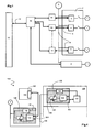
- a type of motor control 1 by an iMCC 2 type board is illustrated in FIG. figure 1 in which each motor 1 is associated with a line starting device 4.
- An architecture compatible with the invention may be composed of a line 2 comprising up to 120 motors 1, or it may be in the form of a juxtaposition of lines, for example 20 columns 2, 2 'each comprising up to 20 motors 1; it is understood that the terms rows and columns serve just to differentiate the elements and, although the columns are indeed often composed of an overlay on a height of the order of 2 m to 2.2 m of departures 4, the notion verticality is only relative.
- the line feeder is an electronic protection relay 4, fed by a current line 6, for example 24 V DC current, which transmits the information it receives via a communication bus 8, for example in Modbus® SL protocol, to a controller 10, which also controls each of the relays 4.
- the controller 10 can be located relatively far away from the control panel 2, and the communication is carried out conventionally by an Ethernet link 12 for example according to a TCP / IP protocol.
- an Ethernet converter 14 is associated with each communication bus 8 of a relay 4, and a switch 16 common to the array 2, 2 'connects the converters 14 to be connected by the Ethernet link 12 to the controller 10
- the iMCC 2 is able to update its information, both at the control reception and at the command sending, every 500 ms, preferably every 200 ms.
- the supply line 6 of the relays 4 is in any case present in the control-command tables 2: according to the invention, it is a question of communicating the programmable logic controller 10 and the motor starters 4 by a PLC technology (current The principle of PLC communication is based on the injection into a cable, parallel to the passage of the supply current, of a different frequency signal which will be detected by appropriate means; in the context of the invention, the frequency used is preferably higher than that of the power supply, in particular of the order of 1 to 30 MHz.
- the CPL addressing protocol is compatible with existing communication systems; it is therefore not necessary to modify the TCP protocol of the architectures according to the figure 1 .
- the invention applies in the previous case of auxiliary power supply V in 24 DC or 48 DC, but also for 110 or 230 V AC, or even 24 or 400 V AC, or any other voltage.
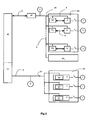
- FIG 2 is schematically shown a table 20 according to the principle of the invention, where are preserved the most possible previous elements, that is to say that neither the controller 10 nor the relays 4, nor their means of communication 8 are not modified;
- Table 20 is schematically represented as a set of p columns 20 i .
- Each relay 4 is thus on the one hand powered by the power supply line 6, and on the other hand connected by its communication means 8 to a first device CPL 22, which is also connected to the current line 6 : the PLC device 22 is of the receiver / converter type and allows a signal flowing on the current line 6 to be transmitted by the bus 8 to the relay 4, and vice versa.
- the second means 12 for communication and control of the controller 10 remain similar and include an Ethernet link 12, the signal CPL 24 from the different devices 22 is converted a second time for Ethernet, at a level of second device CPL 26 master ("power line master "), the network 6, 22, 26 of Table 20 then being star.
- the communication means of the PLC 10 'by deleting the Ethernet line 12 and direct communication by PLC the CPL signal 24' then flowing on the supply line 6 'can be read and / or generated directly by the PLC 10 '.
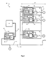
- a table 20 thus comprises p columns 20 i each comprising q i modules 28 for each q q engines 1 of each column 20 i ; for the sake of brevity, the indices i relative to the columns will be omitted in the remainder of the description, the distinction between the columns of a table 20 relating to the construction of the iMCC rather than to its operation.
- Each module 28 comprises a motor starter device 4 which is associated with a carrier current interface 30.
- the PLC interface 30 comprises a signal conversion / reception device 32 associated with first communication means 34 and connected to a main line current 36, which can be connected to the power supply line 6 by means of a first power input system 38.
- the conversion means 32 make it possible to transform the information passing through the first communication means 34 according to a first representative CPL signal protocol able to flow in the current line 36 and then the supply line 6, and vice versa.
- the first communication means 34 are connected to the line feeder 4.
- p columns 20 i of q outputs 4 j each are managed simultaneously, and therefore, near each of the q ⁇ p first CPL interfaces 30 connected to the supply network 6 is an electronic relay 4, which is also powered by the network 6.
- the starting devices 4 which are directly associated with them have, by their nature, a low impedance, which is unfavorable to the propagation of PLC signals.
- the impedance of the line feeder 4 is then preferably raised by an impedance increasing device 40, for example two inductors, set up on its line of 42.
- the impedance increasing device 40 is suitable for all types of power supply that can be encountered (direct or alternating current, PLC transmission at different frequencies); for example, for application to motors 1 and with line feeders 4 which may be the same electronic relays as before, the impedance Z 40 may be of the order of 500 ⁇ .
- the impedance adapter device 40 of the motor starter 4 is also integrated with the first carrier current interface 30: the power supply 42 of the line feeder 4 is realized through the interface CPL 30 which then comprises an auxiliary current line 44, between an input 46, which is preferably derived from the main current line 36 at the level of input power system 38, and an output 48 for connecting the power supply line 42 of the line feeder 34.
- the auxiliary line 44 is set up the impedance Z 40 .
- the standard impedance Z 32 of a converter / receiver LC 32 is of the order of about 50 ⁇ ; the overall impedance of the line CPL, also feed line, 6, 36 decreases significantly due to the paralleling of the different interfaces 30 additional to the operating elements 4 of the motors 1 on a relatively short line 6.
- this low impedance of the line deteriorates the propagation of the signals CPL 24, deterioration of the communication which can take place between the most distant points 4, 1 , 4, p, q of the line 6, 36, but also between two physically close points 4 1 , 4 2 , distant for example from 10 to 20 cm; the correct operation of the installation and the motors 1 may be lessened or even prevented.
- the impedance matching device 50 allows the impedance of the input module 28 to have at least a first low value and a second high value.
- the second carrier current interface 30 ' (that is to say the central master product), which is not implemented. parallel with all the others.
- the second CPL interface 30 ' preferably retains the first low standard impedance (of the order of approximately 50 ⁇ ), whereas the other CPL interfaces 30, connected to the starting relays 4 of the motors 1, have their impedance adapted by insertion of the circuit 50 previously defined so that the module 28 takes a second high value of impedance.
- the second master CPL product 30 ' is intended for communication between the module cabinet 20 according to the invention 28 and a control and control head device 52, for example a PLC or a computer.
- the central PLC interface 30 comprises signal conversion means 32' associated with second communication means 54 and connected to the power supply line 6; the conversion means 32 'make it possible to transform the information passing through the second communication means 54 which are connected to the control system 52 into a representative PLC signal that can circulate in the supply line 6, and vice versa.
- all the carrier current interfaces 30, 30 'relating to a control architecture 56 comprising a switchboard 20 according to the invention are identical.
- the conversion means 32 of the CPL interface 30 allow conversion of the CPL signals to convey them by two communication means 34, 54 which may be different and are selected for connection to the head apparatus 52 or a relay 4 according to the location of the product 30, 30 'in the network 56.
- one embodiment relates to the formation of the power supply input system 38 of the interface 30 in two inputs to two branches 58 , 60 separate from the main current line 36.
- the first branch 58 single current line, corresponds to a first low impedance input, mainly the standard impedance Z 32 , and will be used for the central 30 'CPL product connected to the controller 52;
- the second branch 60 comprises the impedance matching device 50: this high impedance input (Z 32 + Z 50 ) is used for the modules 28 according to the invention.
- the PLC interface 30 further comprises the impedance matching device 40 of the motor starter 4, the branch 46 of the auxiliary line 44 is formed on the second branch 60, between the input system 38 and the impedance 50.
- the impedance matching relating to the paralleling of numerous CPL interfaces is optimized by the implementation of an architecture 56 implementing products whose impedances added according to the invention have adjustable values. ; the value Z of the added impedances can then be chosen according to the type of topology (p, q) of the line CPL and / or the number p ⁇ q of interfaces connected to the line and / or the location i, j of the connected interface on the line.
- FIG 4 A second embodiment of a module 128 according to the invention is illustrated in figure 4 , the reference signs being increased by 100 with respect to the first embodiment.
- the CPL interface 130 may be used as the master or converter of the line input devices 104; it advantageously comprises an auxiliary current line 144 with a fixed or variable impedance adapter 140 of the line input device 104.
- the LC interfaces 130 comprise a main current line 136 of the LC converter / receiver 132 on which is inserted a variable impedance device 150, whose impedance can be adjusted between two values, in particular between zero and a maximum value; the setting can be manual, for example by a potentiometer type setting means, or realized by software programming, with an electronic means 162 which adjusts the value of the impedance Z 150 according to a predetermined value.
- the optimized values of the Z 150 impedances are stored in a memory of said electronic adjustment means 162.
- the electronic adjustment means 162 may in particular be part of the control-and-control device 152.
- the predetermined value of the Z impedances 150 to be adjusted can be calculated; alternately, especially if the architecture 156 is complex, once the geometry of the network 106, 120 defined, "tables of values" can be trained by learning with measurements or by simulations on a line simulation tool CPL and stored; the optimized value of the impedance Z 150 is then parameterized on the interface CPL 130 during the installation.
- the adaptation of the different impedances 150 of the first CPL interfaces 130 present on the iMCC 120 according to the invention is refined by automating a product-by-product adjustment during the installation phase of the modules 128 according to the invention.
- the implementation of the control-command architecture 156 is achieved by connecting each module 128 successively; the additional attenuation of the signal CPL due to the connection on a table 120 of n modules 128 of a new interface 130 n + 1 (and thus of a product of low impedance of fault on the line 106) is sufficiently low that it is possible to communicate information by CPL.
- an arranged algorithm can be implemented in the determination means, and for example integrated in the process of scanning mode of production.
- a constant exchange of information is realized between the head unit 152 and the CPL conversion / reception devices 132 for controlling and controlling the line feeders 104 (in particular every 200 msec): it is possible to to add broadcast- type requests which interrogate the whole network in parallel, or from time to time, to check if there is another CPL architecture 130 on line 106; here again, the speed of the exchanges implies a minor modification of the architecture 156 so that the resulting CPL signal is not strongly attenuated and can transmit the necessary information. If this is the case, the production mode polling process and the previously described automatic impedance adjustment process are mixed in time until the automatic tuning process is complete.
- the adaptations of the impedances of a CPL communication system are optimized for the particular use in iMCCs, and this for each architecture of the network.
- the use of PLC communication becomes possible in this application, where reliability is imperative.
- the CPL solution is conceivable and advantageous.
- the installation of additional impedances and their adaptation to the existing arrays is not a problem, and it is possible to switch from a conventional, non-communicating array to an iMCC panel: a renovation without complete restructuring or replacement for similar results is allowed by the principle according to the invention.
Landscapes
- Engineering & Computer Science (AREA)
- Power Engineering (AREA)
- Computer Networks & Wireless Communication (AREA)
- Signal Processing (AREA)
- Cable Transmission Systems, Equalization Of Radio And Reduction Of Echo (AREA)
- Programmable Controllers (AREA)
- Remote Monitoring And Control Of Power-Distribution Networks (AREA)
- Small-Scale Networks (AREA)
- Selective Calling Equipment (AREA)
Applications Claiming Priority (1)
| Application Number | Priority Date | Filing Date | Title |
|---|---|---|---|
| FR0704522A FR2917922B1 (fr) | 2007-06-25 | 2007-06-25 | Communication par courant porteur pour les tableaux centralises de commande |
Publications (2)
| Publication Number | Publication Date |
|---|---|
| EP2009808A1 true EP2009808A1 (de) | 2008-12-31 |
| EP2009808B1 EP2009808B1 (de) | 2011-08-03 |
Family
ID=38983419
Family Applications (1)
| Application Number | Title | Priority Date | Filing Date |
|---|---|---|---|
| EP08354034A Ceased EP2009808B1 (de) | 2007-06-25 | 2008-06-05 | Kommunikation über Trägerstrom an die zentralen Schalttafeln |
Country Status (5)
| Country | Link |
|---|---|
| US (1) | US20080316005A1 (de) |
| EP (1) | EP2009808B1 (de) |
| JP (1) | JP2009005361A (de) |
| AT (1) | ATE519283T1 (de) |
| FR (1) | FR2917922B1 (de) |
Families Citing this family (7)
| Publication number | Priority date | Publication date | Assignee | Title |
|---|---|---|---|---|
| KR101008655B1 (ko) | 2009-07-27 | 2011-01-17 | 주식회사 일렉슨 | n 코어 전선을 이용한 통신 제어 방법 및 장치 |
| CN103403635B (zh) * | 2011-03-04 | 2015-11-25 | 株式会社安川电机 | 控制装置 |
| JP5819023B2 (ja) * | 2013-03-29 | 2015-11-18 | 三菱電機株式会社 | Plcシステム |
| CN105024731B (zh) * | 2015-08-26 | 2017-06-16 | 上海斐讯数据通信技术有限公司 | 一种电力线网络产品测试系统 |
| CN107065711A (zh) * | 2017-06-16 | 2017-08-18 | 重庆市灵龙自动化设备有限公司 | 一种智能流水线控制系统 |
| JP7335705B2 (ja) * | 2019-02-05 | 2023-08-30 | 東芝産業機器システム株式会社 | モータコントロールセンタ |
| WO2020237665A1 (zh) * | 2019-05-31 | 2020-12-03 | 西门子股份公司 | 协助用户使用自动化系统的设备、方法和计算机可读介质 |
Citations (2)
| Publication number | Priority date | Publication date | Assignee | Title |
|---|---|---|---|---|
| DE10131189A1 (de) * | 2000-07-13 | 2002-05-16 | Xeline Co | Stromleitungsverbindungsvorrichtung zur Stromleitungskommunikation auf einem Niederspannungsstromleitungsverteilungsnetz |
| JP2005157747A (ja) | 2003-11-26 | 2005-06-16 | Mitsubishi Electric Corp | プラント制御システム |
Family Cites Families (11)
| Publication number | Priority date | Publication date | Assignee | Title |
|---|---|---|---|---|
| JPS54157020A (en) * | 1978-05-31 | 1979-12-11 | Matsushita Electric Works Ltd | Carrier transmitter |
| US4302750A (en) * | 1979-08-03 | 1981-11-24 | Compuguard Corporation | Distribution automation system |
| JP3713477B2 (ja) * | 2001-11-19 | 2005-11-09 | Tdk株式会社 | 電力線通信システム |
| JP4144737B2 (ja) * | 2003-04-08 | 2008-09-03 | 三菱電機株式会社 | ケーブル延線機制御システム |
| JP4121984B2 (ja) * | 2004-07-15 | 2008-07-23 | 株式会社ケーヒン | アイドル停止制御装置 |
| JP4575069B2 (ja) * | 2004-07-30 | 2010-11-04 | 矢崎総業株式会社 | 車両用電源重畳多重通信システム |
| JP4423157B2 (ja) * | 2004-10-06 | 2010-03-03 | キヤノン株式会社 | 電力線通信装置およびその制御方法 |
| JP4975291B2 (ja) * | 2004-11-09 | 2012-07-11 | 株式会社ダイヘン | インピーダンス整合装置 |
| JP4499598B2 (ja) * | 2005-03-31 | 2010-07-07 | 矢崎総業株式会社 | 電源重畳多重通信システム |
| DE112007001801B4 (de) * | 2006-09-29 | 2016-12-29 | Mitsubishi Electric Corporation | Stromleitungskommunikationsvorrichtung |
| US8130084B2 (en) * | 2007-04-30 | 2012-03-06 | International Business Machines Corporation | Fault tolerant closed system control using power line communication |
-
2007
- 2007-06-25 FR FR0704522A patent/FR2917922B1/fr not_active Expired - Fee Related
-
2008
- 2008-06-05 AT AT08354034T patent/ATE519283T1/de not_active IP Right Cessation
- 2008-06-05 EP EP08354034A patent/EP2009808B1/de not_active Ceased
- 2008-06-10 US US12/155,799 patent/US20080316005A1/en not_active Abandoned
- 2008-06-24 JP JP2008164813A patent/JP2009005361A/ja active Pending
Patent Citations (2)
| Publication number | Priority date | Publication date | Assignee | Title |
|---|---|---|---|---|
| DE10131189A1 (de) * | 2000-07-13 | 2002-05-16 | Xeline Co | Stromleitungsverbindungsvorrichtung zur Stromleitungskommunikation auf einem Niederspannungsstromleitungsverteilungsnetz |
| JP2005157747A (ja) | 2003-11-26 | 2005-06-16 | Mitsubishi Electric Corp | プラント制御システム |
Also Published As
| Publication number | Publication date |
|---|---|
| FR2917922B1 (fr) | 2009-07-31 |
| EP2009808B1 (de) | 2011-08-03 |
| ATE519283T1 (de) | 2011-08-15 |
| US20080316005A1 (en) | 2008-12-25 |
| FR2917922A1 (fr) | 2008-12-26 |
| JP2009005361A (ja) | 2009-01-08 |
Similar Documents
| Publication | Publication Date | Title |
|---|---|---|
| EP2009808B1 (de) | Kommunikation über Trägerstrom an die zentralen Schalttafeln | |
| US6167120A (en) | Apparatus and methods for home networking | |
| EP2047609B1 (de) | Netzwerksystem mit hoher verfügbarkeit | |
| FR2606234A1 (fr) | Systeme de radio bus | |
| EP1179760B9 (de) | Automatisiertes internes Bussystem zur Unterstützung des TCP/IP Protokolls | |
| FR2750276A1 (fr) | Procede de commande de transfert d'informations entre les composants ainsi que composants pour la mise en oeuvre du procede | |
| EP0689310A1 (de) | Verfahren, Sender und Empfänger zur Nachrichtenübertragung durch Packete | |
| EP2368329A1 (de) | Elektronische einrichtung mit einem trägerstrom | |
| FR2936662A1 (fr) | Procede d'organisation d'un reseau electrique comportant plusieurs sources d'energie, repartiteur et installations | |
| FR2936365A1 (fr) | Dispositif antennaire autonome a commutation de pointage rapide | |
| EP2064926B1 (de) | Verfahren und vorrichtung zur informationsübertragung über ein komplexes netzwerk | |
| FR2920721B1 (fr) | Procede de commande de systeme de generation de puissance pour vehicule | |
| FR2698748A1 (fr) | Réseau hertzien et procédé pour transmettre des services supplémentaires dans ce réseau. | |
| EP0770286A1 (de) | Verfahren und vorrichtung zur übertragung zwischen einer vielzahl von an unterschiedliche elektrische versorgungsnetze angeschlossenlokalen einheiten | |
| EP0694238A1 (de) | Verfahren zur erhöhung der übertragunggeschwindigkeit | |
| WO2012140345A2 (fr) | Systeme de gestion de charge de vehicule electrique ou hybride | |
| FR2977415A1 (fr) | Reseau d'interconnexion d'equipements pour vehicules par courants porteurs en ligne | |
| FR2798024A1 (fr) | Procede et dispositif de communication dans un reseau de type centralise et reseau comportant un tel dispositif | |
| EP2814130A1 (de) | Elektrische Anlage mit verbessertem Schnittstellenmodul | |
| Maffei et al. | A modular gigabit Ethernet backbone for NEPTUNE and other ocean observatories | |
| FR3088472A1 (fr) | Procede d'echange de donnees dans un aeronef et unite de controle | |
| FR2508668A1 (fr) | Systeme de gestion d'un reseau de transport par tubes pneumatiques | |
| FR2669499A1 (fr) | Installation a jeux de lumiere, et organes emetteur et recepteur pour une telle installation. | |
| EP1393088B1 (de) | Vorrichtung zur erhaltung einer elektronischen schaltung in einem vorgegebenen zustand | |
| EP3158656B1 (de) | System zur steuerung von mindestens einem servomotor aus einer befehls-/steuerzentrale |
Legal Events
| Date | Code | Title | Description |
|---|---|---|---|
| PUAI | Public reference made under article 153(3) epc to a published international application that has entered the european phase |
Free format text: ORIGINAL CODE: 0009012 |
|
| AK | Designated contracting states |
Kind code of ref document: A1 Designated state(s): AT BE BG CH CY CZ DE DK EE ES FI FR GB GR HR HU IE IS IT LI LT LU LV MC MT NL NO PL PT RO SE SI SK TR |
|
| AX | Request for extension of the european patent |
Extension state: AL BA MK RS |
|
| RAP1 | Party data changed (applicant data changed or rights of an application transferred) |
Owner name: SCHNEIDER ELECTRIC INDUSTRIES SAS |
|
| AKX | Designation fees paid | ||
| 17P | Request for examination filed |
Effective date: 20090116 |
|
| RBV | Designated contracting states (corrected) |
Designated state(s): AT BE BG CH CY CZ DE DK EE ES FI FR GB GR HR HU IE IS IT LI LT LU LV MC MT NL NO PL PT RO SE SI SK TR |
|
| REG | Reference to a national code |
Ref country code: DE Ref legal event code: 8566 |
|
| GRAP | Despatch of communication of intention to grant a patent |
Free format text: ORIGINAL CODE: EPIDOSNIGR1 |
|
| GRAS | Grant fee paid |
Free format text: ORIGINAL CODE: EPIDOSNIGR3 |
|
| GRAA | (expected) grant |
Free format text: ORIGINAL CODE: 0009210 |
|
| AK | Designated contracting states |
Kind code of ref document: B1 Designated state(s): AT BE BG CH CY CZ DE DK EE ES FI FR GB GR HR HU IE IS IT LI LT LU LV MC MT NL NO PL PT RO SE SI SK TR |
|
| REG | Reference to a national code |
Ref country code: GB Ref legal event code: FG4D Free format text: NOT ENGLISH |
|
| REG | Reference to a national code |
Ref country code: CH Ref legal event code: EP |
|
| REG | Reference to a national code |
Ref country code: IE Ref legal event code: FG4D Free format text: LANGUAGE OF EP DOCUMENT: FRENCH |
|
| REG | Reference to a national code |
Ref country code: DE Ref legal event code: R096 Ref document number: 602008008601 Country of ref document: DE Effective date: 20110929 |
|
| REG | Reference to a national code |
Ref country code: NL Ref legal event code: VDEP Effective date: 20110803 |
|
| LTIE | Lt: invalidation of european patent or patent extension |
Effective date: 20110803 |
|
| PG25 | Lapsed in a contracting state [announced via postgrant information from national office to epo] |
Ref country code: SE Free format text: LAPSE BECAUSE OF FAILURE TO SUBMIT A TRANSLATION OF THE DESCRIPTION OR TO PAY THE FEE WITHIN THE PRESCRIBED TIME-LIMIT Effective date: 20110803 Ref country code: PT Free format text: LAPSE BECAUSE OF FAILURE TO SUBMIT A TRANSLATION OF THE DESCRIPTION OR TO PAY THE FEE WITHIN THE PRESCRIBED TIME-LIMIT Effective date: 20111205 Ref country code: FI Free format text: LAPSE BECAUSE OF FAILURE TO SUBMIT A TRANSLATION OF THE DESCRIPTION OR TO PAY THE FEE WITHIN THE PRESCRIBED TIME-LIMIT Effective date: 20110803 Ref country code: LT Free format text: LAPSE BECAUSE OF FAILURE TO SUBMIT A TRANSLATION OF THE DESCRIPTION OR TO PAY THE FEE WITHIN THE PRESCRIBED TIME-LIMIT Effective date: 20110803 Ref country code: HR Free format text: LAPSE BECAUSE OF FAILURE TO SUBMIT A TRANSLATION OF THE DESCRIPTION OR TO PAY THE FEE WITHIN THE PRESCRIBED TIME-LIMIT Effective date: 20110803 Ref country code: NL Free format text: LAPSE BECAUSE OF FAILURE TO SUBMIT A TRANSLATION OF THE DESCRIPTION OR TO PAY THE FEE WITHIN THE PRESCRIBED TIME-LIMIT Effective date: 20110803 Ref country code: NO Free format text: LAPSE BECAUSE OF FAILURE TO SUBMIT A TRANSLATION OF THE DESCRIPTION OR TO PAY THE FEE WITHIN THE PRESCRIBED TIME-LIMIT Effective date: 20111103 Ref country code: IS Free format text: LAPSE BECAUSE OF FAILURE TO SUBMIT A TRANSLATION OF THE DESCRIPTION OR TO PAY THE FEE WITHIN THE PRESCRIBED TIME-LIMIT Effective date: 20111203 |
|
| REG | Reference to a national code |
Ref country code: AT Ref legal event code: MK05 Ref document number: 519283 Country of ref document: AT Kind code of ref document: T Effective date: 20110803 |
|
| PG25 | Lapsed in a contracting state [announced via postgrant information from national office to epo] |
Ref country code: AT Free format text: LAPSE BECAUSE OF FAILURE TO SUBMIT A TRANSLATION OF THE DESCRIPTION OR TO PAY THE FEE WITHIN THE PRESCRIBED TIME-LIMIT Effective date: 20110803 Ref country code: CY Free format text: LAPSE BECAUSE OF FAILURE TO SUBMIT A TRANSLATION OF THE DESCRIPTION OR TO PAY THE FEE WITHIN THE PRESCRIBED TIME-LIMIT Effective date: 20110803 Ref country code: LV Free format text: LAPSE BECAUSE OF FAILURE TO SUBMIT A TRANSLATION OF THE DESCRIPTION OR TO PAY THE FEE WITHIN THE PRESCRIBED TIME-LIMIT Effective date: 20110803 Ref country code: SI Free format text: LAPSE BECAUSE OF FAILURE TO SUBMIT A TRANSLATION OF THE DESCRIPTION OR TO PAY THE FEE WITHIN THE PRESCRIBED TIME-LIMIT Effective date: 20110803 Ref country code: PL Free format text: LAPSE BECAUSE OF FAILURE TO SUBMIT A TRANSLATION OF THE DESCRIPTION OR TO PAY THE FEE WITHIN THE PRESCRIBED TIME-LIMIT Effective date: 20110803 Ref country code: GR Free format text: LAPSE BECAUSE OF FAILURE TO SUBMIT A TRANSLATION OF THE DESCRIPTION OR TO PAY THE FEE WITHIN THE PRESCRIBED TIME-LIMIT Effective date: 20111104 |
|
| REG | Reference to a national code |
Ref country code: IE Ref legal event code: FD4D |
|
| PG25 | Lapsed in a contracting state [announced via postgrant information from national office to epo] |
Ref country code: CZ Free format text: LAPSE BECAUSE OF FAILURE TO SUBMIT A TRANSLATION OF THE DESCRIPTION OR TO PAY THE FEE WITHIN THE PRESCRIBED TIME-LIMIT Effective date: 20110803 Ref country code: SK Free format text: LAPSE BECAUSE OF FAILURE TO SUBMIT A TRANSLATION OF THE DESCRIPTION OR TO PAY THE FEE WITHIN THE PRESCRIBED TIME-LIMIT Effective date: 20110803 Ref country code: IE Free format text: LAPSE BECAUSE OF FAILURE TO SUBMIT A TRANSLATION OF THE DESCRIPTION OR TO PAY THE FEE WITHIN THE PRESCRIBED TIME-LIMIT Effective date: 20110803 |
|
| PG25 | Lapsed in a contracting state [announced via postgrant information from national office to epo] |
Ref country code: EE Free format text: LAPSE BECAUSE OF FAILURE TO SUBMIT A TRANSLATION OF THE DESCRIPTION OR TO PAY THE FEE WITHIN THE PRESCRIBED TIME-LIMIT Effective date: 20110803 Ref country code: RO Free format text: LAPSE BECAUSE OF FAILURE TO SUBMIT A TRANSLATION OF THE DESCRIPTION OR TO PAY THE FEE WITHIN THE PRESCRIBED TIME-LIMIT Effective date: 20110803 |
|
| PLBE | No opposition filed within time limit |
Free format text: ORIGINAL CODE: 0009261 |
|
| STAA | Information on the status of an ep patent application or granted ep patent |
Free format text: STATUS: NO OPPOSITION FILED WITHIN TIME LIMIT |
|
| PG25 | Lapsed in a contracting state [announced via postgrant information from national office to epo] |
Ref country code: DK Free format text: LAPSE BECAUSE OF FAILURE TO SUBMIT A TRANSLATION OF THE DESCRIPTION OR TO PAY THE FEE WITHIN THE PRESCRIBED TIME-LIMIT Effective date: 20110803 |
|
| 26N | No opposition filed |
Effective date: 20120504 |
|
| REG | Reference to a national code |
Ref country code: DE Ref legal event code: R097 Ref document number: 602008008601 Country of ref document: DE Effective date: 20120504 |
|
| BERE | Be: lapsed |
Owner name: SCHNEIDER ELECTRIC INDUSTRIES SAS Effective date: 20120630 |
|
| PG25 | Lapsed in a contracting state [announced via postgrant information from national office to epo] |
Ref country code: MC Free format text: LAPSE BECAUSE OF NON-PAYMENT OF DUE FEES Effective date: 20120630 |
|
| REG | Reference to a national code |
Ref country code: CH Ref legal event code: PL |
|
| REG | Reference to a national code |
Ref country code: CH Ref legal event code: PL |
|
| GBPC | Gb: european patent ceased through non-payment of renewal fee |
Effective date: 20120605 |
|
| PG25 | Lapsed in a contracting state [announced via postgrant information from national office to epo] |
Ref country code: LI Free format text: LAPSE BECAUSE OF NON-PAYMENT OF DUE FEES Effective date: 20120630 Ref country code: ES Free format text: LAPSE BECAUSE OF FAILURE TO SUBMIT A TRANSLATION OF THE DESCRIPTION OR TO PAY THE FEE WITHIN THE PRESCRIBED TIME-LIMIT Effective date: 20111114 Ref country code: CH Free format text: LAPSE BECAUSE OF NON-PAYMENT OF DUE FEES Effective date: 20120630 Ref country code: GB Free format text: LAPSE BECAUSE OF NON-PAYMENT OF DUE FEES Effective date: 20120605 Ref country code: BE Free format text: LAPSE BECAUSE OF NON-PAYMENT OF DUE FEES Effective date: 20120630 |
|
| PG25 | Lapsed in a contracting state [announced via postgrant information from national office to epo] |
Ref country code: BG Free format text: LAPSE BECAUSE OF FAILURE TO SUBMIT A TRANSLATION OF THE DESCRIPTION OR TO PAY THE FEE WITHIN THE PRESCRIBED TIME-LIMIT Effective date: 20111103 |
|
| PG25 | Lapsed in a contracting state [announced via postgrant information from national office to epo] |
Ref country code: MT Free format text: LAPSE BECAUSE OF FAILURE TO SUBMIT A TRANSLATION OF THE DESCRIPTION OR TO PAY THE FEE WITHIN THE PRESCRIBED TIME-LIMIT Effective date: 20110803 |
|
| PG25 | Lapsed in a contracting state [announced via postgrant information from national office to epo] |
Ref country code: TR Free format text: LAPSE BECAUSE OF FAILURE TO SUBMIT A TRANSLATION OF THE DESCRIPTION OR TO PAY THE FEE WITHIN THE PRESCRIBED TIME-LIMIT Effective date: 20110803 |
|
| PG25 | Lapsed in a contracting state [announced via postgrant information from national office to epo] |
Ref country code: LU Free format text: LAPSE BECAUSE OF NON-PAYMENT OF DUE FEES Effective date: 20120605 |
|
| PG25 | Lapsed in a contracting state [announced via postgrant information from national office to epo] |
Ref country code: HU Free format text: LAPSE BECAUSE OF FAILURE TO SUBMIT A TRANSLATION OF THE DESCRIPTION OR TO PAY THE FEE WITHIN THE PRESCRIBED TIME-LIMIT Effective date: 20080605 |
|
| REG | Reference to a national code |
Ref country code: FR Ref legal event code: PLFP Year of fee payment: 8 |
|
| REG | Reference to a national code |
Ref country code: FR Ref legal event code: PLFP Year of fee payment: 9 |
|
| REG | Reference to a national code |
Ref country code: FR Ref legal event code: PLFP Year of fee payment: 10 |
|
| REG | Reference to a national code |
Ref country code: FR Ref legal event code: PLFP Year of fee payment: 11 |
|
| PGFP | Annual fee paid to national office [announced via postgrant information from national office to epo] |
Ref country code: DE Payment date: 20240627 Year of fee payment: 17 |
|
| PGFP | Annual fee paid to national office [announced via postgrant information from national office to epo] |
Ref country code: FR Payment date: 20240625 Year of fee payment: 17 |
|
| PGFP | Annual fee paid to national office [announced via postgrant information from national office to epo] |
Ref country code: IT Payment date: 20240619 Year of fee payment: 17 |
|
| REG | Reference to a national code |
Ref country code: DE Ref legal event code: R119 Ref document number: 602008008601 Country of ref document: DE |
|
| PG25 | Lapsed in a contracting state [announced via postgrant information from national office to epo] |
Ref country code: DE Free format text: LAPSE BECAUSE OF NON-PAYMENT OF DUE FEES Effective date: 20260101 |
|
| PG25 | Lapsed in a contracting state [announced via postgrant information from national office to epo] |
Ref country code: IT Free format text: LAPSE BECAUSE OF NON-PAYMENT OF DUE FEES Effective date: 20250605 |
|
| PG25 | Lapsed in a contracting state [announced via postgrant information from national office to epo] |
Ref country code: FR Free format text: LAPSE BECAUSE OF NON-PAYMENT OF DUE FEES Effective date: 20250630 |