EP2009909A2 - Stabilisateur d'image - Google Patents
Stabilisateur d'image Download PDFInfo
- Publication number
- EP2009909A2 EP2009909A2 EP08010633A EP08010633A EP2009909A2 EP 2009909 A2 EP2009909 A2 EP 2009909A2 EP 08010633 A EP08010633 A EP 08010633A EP 08010633 A EP08010633 A EP 08010633A EP 2009909 A2 EP2009909 A2 EP 2009909A2
- Authority
- EP
- European Patent Office
- Prior art keywords
- axis
- actuator
- sensor
- image stabilizer
- movable member
- Prior art date
- Legal status (The legal status is an assumption and is not a legal conclusion. Google has not performed a legal analysis and makes no representation as to the accuracy of the status listed.)
- Withdrawn
Links
- 239000003381 stabilizer Substances 0.000 title claims abstract description 43
- 238000003384 imaging method Methods 0.000 claims abstract description 57
- 230000003287 optical effect Effects 0.000 claims description 29
- 238000001514 detection method Methods 0.000 claims description 11
- 230000004907 flux Effects 0.000 claims description 8
- 230000008859 change Effects 0.000 claims description 3
- 230000005389 magnetism Effects 0.000 claims description 2
- 230000007246 mechanism Effects 0.000 description 28
- 238000005452 bending Methods 0.000 description 7
- 230000004048 modification Effects 0.000 description 6
- 238000012986 modification Methods 0.000 description 6
- 238000010586 diagram Methods 0.000 description 5
- 238000013016 damping Methods 0.000 description 3
- 230000006870 function Effects 0.000 description 3
- 239000000463 material Substances 0.000 description 3
- 230000011514 reflex Effects 0.000 description 3
- 238000004891 communication Methods 0.000 description 2
- 230000001105 regulatory effect Effects 0.000 description 2
- 125000006850 spacer group Chemical group 0.000 description 2
- 208000036829 Device dislocation Diseases 0.000 description 1
- 229910052782 aluminium Inorganic materials 0.000 description 1
- XAGFODPZIPBFFR-UHFFFAOYSA-N aluminium Chemical compound [Al] XAGFODPZIPBFFR-UHFFFAOYSA-N 0.000 description 1
- 239000000919 ceramic Substances 0.000 description 1
- 238000006243 chemical reaction Methods 0.000 description 1
- 230000000295 complement effect Effects 0.000 description 1
- 230000007423 decrease Effects 0.000 description 1
- 239000000428 dust Substances 0.000 description 1
- 239000013013 elastic material Substances 0.000 description 1
- 239000004973 liquid crystal related substance Substances 0.000 description 1
- 229910044991 metal oxide Inorganic materials 0.000 description 1
- 150000004706 metal oxides Chemical class 0.000 description 1
- 238000005375 photometry Methods 0.000 description 1
- 239000011347 resin Substances 0.000 description 1
- 229920005989 resin Polymers 0.000 description 1
- 239000004065 semiconductor Substances 0.000 description 1
- 230000001360 synchronised effect Effects 0.000 description 1
- 229910000859 α-Fe Inorganic materials 0.000 description 1
Images






Classifications
-
- G—PHYSICS
- G02—OPTICS
- G02B—OPTICAL ELEMENTS, SYSTEMS OR APPARATUS
- G02B27/00—Optical systems or apparatus not provided for by any of the groups G02B1/00 - G02B26/00, G02B30/00
- G02B27/64—Imaging systems using optical elements for stabilisation of the lateral and angular position of the image
- G02B27/646—Imaging systems using optical elements for stabilisation of the lateral and angular position of the image compensating for small deviations, e.g. due to vibration or shake
-
- G—PHYSICS
- G03—PHOTOGRAPHY; CINEMATOGRAPHY; ANALOGOUS TECHNIQUES USING WAVES OTHER THAN OPTICAL WAVES; ELECTROGRAPHY; HOLOGRAPHY
- G03B—APPARATUS OR ARRANGEMENTS FOR TAKING PHOTOGRAPHS OR FOR PROJECTING OR VIEWING THEM; APPARATUS OR ARRANGEMENTS EMPLOYING ANALOGOUS TECHNIQUES USING WAVES OTHER THAN OPTICAL WAVES; ACCESSORIES THEREFOR
- G03B5/00—Adjustment of optical system relative to image or object surface other than for focusing
-
- H—ELECTRICITY
- H04—ELECTRIC COMMUNICATION TECHNIQUE
- H04N—PICTORIAL COMMUNICATION, e.g. TELEVISION
- H04N23/00—Cameras or camera modules comprising electronic image sensors; Control thereof
- H04N23/50—Constructional details
- H04N23/54—Mounting of pick-up tubes, electronic image sensors, deviation or focusing coils
-
- H—ELECTRICITY
- H04—ELECTRIC COMMUNICATION TECHNIQUE
- H04N—PICTORIAL COMMUNICATION, e.g. TELEVISION
- H04N23/00—Cameras or camera modules comprising electronic image sensors; Control thereof
- H04N23/60—Control of cameras or camera modules
- H04N23/68—Control of cameras or camera modules for stable pick-up of the scene, e.g. compensating for camera body vibrations
Definitions
- the present invention relates to an image stabilizer that corrects for shake on a hand-held shot with an imaging apparatus.
- Japanese Patent Application Laid-open No. 2006-81348 discloses an example of an image stabilizer.
- the image stabilizer shifts, by an actuator, an imaging device such as a charge-coupled device (CCD) in a plane perpendicular to the imaging optical axis in the horizontal and vertical directions independently of each other.
- CCD charge-coupled device
- the image stabilizer corrects the position on the imaging surface of the imaging device where light rays reflected from an object are focused.
- a position sensor is arranged on the outside of the actuator for moving the imaging device.
- An image stabilizer is for correcting a position on a surface of a rectangular imaging device where light rays reflected from an object are focused.
- the image stabilizer includes a fixed member that includes a first actuator including a piezoelectric element having as a whole an elongated shape, the fixed member being arranged near a first side of the imaging device in parallel with a direction of the first side; a first movable member that includes a second actuator including a piezoelectric element having as a whole an elongated shape, the first movable member being arranged near a second side of the imaging device perpendicular to the first side in parallel with a direction of the second side, the first movable member moving, when driven by the first actuator, in the direction of the first side on the fixed member; a second movable member that is mounted with the imaging device and moves, when driven by the second actuator, in the direction of the second side on the first movable member; and a position sensor that detects the relative position of the imaging device moved
- the first actuator is located near a virtual intersection of the longitudinal axis of the first actuator and the longitudinal axis of the second actuator not to interfere with the second actuator.
- the second actuator is located near the virtual intersection not to interfere with the first actuator.
- the position sensor is located in a region that is partly surrounded by an edge of the first actuator and the second actuator and that includes the virtual intersection.
- an image stabilizer that corrects hand-shake in an imaging unit including an imaging device that obtains an image signal by photoelectric conversion, and that is applied to, for example, a single-lens reflex electronic camera with interchangeable lenses.
- FIG. 1 is a schematic block diagram mainly showing an electrical system configuration of the electronic camera.
- the system configuration of the electronic camera includes a body unit 100 as the main body, and a lens unit 10 used as an interchangeable lens, which is one of accessories of the camera.
- the lens unit 10 is detachably attached to the body unit 100 through a lens mount (not shown) on the front of the body unit 100.
- the lens unit 10 includes a microcomputer (hereinafter, "Lucom”) 5 that controls the lens unit 10.
- the body unit 100 includes a microcomputer (hereinafter, "Bucom”) 50 that controls the body unit 100.
- the Lucom 5 and the Bucom 50 are electrically connected to each other via a communication connector 6 so that they can communicate with each other.
- the camera system is configured such that the Lucom 5 operates dependently and in cooperation with the Bucom 50.
- the lens unit 10 further includes an imaging lens 1, a lens drive mechanism 2, an aperture 3, and an aperture drive mechanism 4.
- the imaging lens 1 is driven by a direct-current (DC) motor (not shown) provided in the lens drive mechanism 2.
- the aperture 3 is driven by a stepper motor (not shown) provided in the aperture drive mechanism 4.
- the Lucom 5 controls the motors according to an instruction from the Bucom 50.
- the body unit 100 is provided therein with single-lens reflex components, a focal plane shutter 15 arranged on the imaging optical axis, and an auto-focus (AF) sensor unit 16.
- the single-lens reflex components constitute an imaging optical system, and include a quick-return mirror 11, a pentaprism 12, an eyepiece 13, and a submirror 11a.
- the AF sensor unit 16 receives light rays reflected from the submirror 11a, and detects a defocus amount.
- the body unit 100 is further provided therein with an AF sensor drive circuit 17, a mirror drive mechanism 18, a shutter charge mechanism 19, a shutter control circuit 20, and a photometric circuit 21.
- the AF sensor drive circuit 17 controls the drive of the AF sensor unit 16.
- the mirror drive mechanism 18 controls the drive of the quick-return mirror 11.
- the shutter charge mechanism 19 charges a spring for driving the front and rear curtains of the shutter 15.
- the shutter control circuit 20 controls the motion of the front and rear curtains.
- the photometric circuit 21 performs photometric measurements based on output rays from the pentaprism 12 detected by a photometric sensor 21a.
- the imaging unit 30 On the imaging optical axis is arranged an imaging unit 30 that converts light reflected from an object and having passed through the imaging optical system into an electrical signal.
- the imaging unit 30 includes a charge-coupled device (CCD) 31 as an imaging device, an optical low-pass filter (LPF) 32, and a dust-proof filter 33.
- a piezoelectric element 34 On the circumference of the dust-proof filter 33 is provided a piezoelectric element 34.
- the piezoelectric element 34 has two electrodes.
- a dust-proof filter control circuit 48 causes the piezoelectric element 34 to vibrate at a predetermined frequency to vibrate the dust-proof filter 33, thereby removing dust from the filter surface.
- the imaging unit 30 further includes an image stabilizer 300 that corrects for camera shake, described later.
- the camera system further includes a CCD interface circuit 23 connected to the CCD 31 and an image processing controller 28.
- the image processing controller 28 performs image processing using a liquid crystal display (LCD) monitor 24, and as storage areas, synchronous dynamic random access memory (SDRAM) 25 and a flash read only memory (ROM) 26, and the like.
- LCD liquid crystal display
- SDRAM synchronous dynamic random access memory
- ROM flash read only memory
- the camera system is configured to be capable of providing electronic storage/display function as well as electronic imaging function.
- a recording medium 27 is configured to be communicably connected to the electronic camera via a communication connector and disconnectable therefrom.
- the recording medium 27 is an external storage medium, examples of which include various types of memory cards and an external hard disk drive (HDD). Image data captured by the electronic camera is stored in the recording medium 27.
- a nonvolatile memory 29 is provided that is formed of an electrically erasable programmable read only memory (EEPROM).
- EEPROM electrically erasable programmable read only memory
- the Bucom 50 is provided with an LCD 51, a light emitting diode (LED) 51a, and a camera operation switch (SW) 52.
- the LCD 51 and the LED 51a notify a user of the operation state of the electronic camera by the display or output thereof.
- the camera operation SW 52 is a group of switches including operation buttons necessary for operating the electronic camera. Examples of such operation buttons include a release button, a mode switching button and a power button.
- the Bucom 50 is further provided with a battery 54 as a power source, a power source circuit 53, and a voltage detector circuit (not shown).
- the power source circuit 53 converts the voltage of the battery 54 to voltages required to the respective circuit units that constitute the camera system to supply power thereto.
- the voltage detector circuit detects a voltage change due to a current supplied from an external power source via a plug.
- the image processing controller 28 controls the CCD interface circuit 23 to acquire image data from the CCD 31 according to an instruction from the Bucom 50.
- the image data is converted by the image processing controller 28 into a video signal, and is displayed on the LCD monitor 24. From the display on the LCD monitor 24, the user can check an image captured by the electronic camera.
- the imaging unit 30 includes the CCD 31 as an imaging device, the optical LPF 32, the dust-proof filter 33, and the piezoelectric element 34.
- the dust-proof filter 33 is arranged on the front side of the optical LPF 32 such that they face each other with a predetermined spacing between them.
- the imaging surface of the CCD 31 is exposed to light that has passed through the imaging optical system.
- the CCD 31 obtains an image signal corresponding to the light.
- the CCD 31 is rectangle, and on the imaging surface side thereof is arranged the optical LPF 32.
- the optical LPF 32 removes high-frequency components from light reflected from an object and having passed through the imaging optical system.
- the piezoelectric element 34 is arranged on the circumference of the dust-proof filter 33, and vibrates the dust-proof filter 33 at a predetermined amplitude.
- CCD complementary metal oxide semiconductor
- the imaging device can be a complementary metal oxide semiconductor (CMOS) sensor or the like.
- the dust-proof filter 33 as a whole has a plate-like circular (polygonal) shape, and is made of an elastic material such as a plate spring.
- the dust-proof filter 33 is supported while pressed by pressing members 37 that are fixed to the holder 35 with screws 36.
- Z-axis direction refers to the direction of the imaging optical axis
- X-axis direction refers to a first-side direction (longitudinal direction) of the rectangle CCD 31 arranged on the imaging optical axis perpendicular thereto
- Y-axis direction refers to a second-side direction (short-side direction) of the rectangle CCD 31 perpendicular to the first-side direction.
- the image stabilizer 300 moves the CCD 31 in either or both the X-axis direction and the Y-axis direction to correct the position on the imaging surface of the CCD 31 where light rays reflected from an object are focused.
- the image stabilizer 300 uses as a driving source an actuator that generates elliptic vibration in a driving member when applied with a predetermined frequency voltage.
- the image stabilizer 300 moves the holder 35 having the CCD 31 mounted thereon in the imaging unit 30.
- FIG. 2 is a schematic diagram illustrating the operating principle of the vibrator 200.
- the vibrator 200 includes a piezoelectric body 201, a piezoelectric element 204 formed of a pair of driving electrodes 202 and 203, and two drivers 205 and 206 as driving members.
- the piezoelectric body 201 has a predetermined size, and has as a whole an elongated, rectangular shape.
- the driving electrodes 202 and 203 are formed to be symmetrical about the center of the piezoelectric body 201 on one side thereof.
- the drivers 205 and 206 are arranged along an axis in parallel with the central axis of the piezoelectric element 204 on the surface of the piezoelectric body 201 at positions corresponding to the driving electrodes 202 and 203, respectively. If the vibrator 200 generates only longitudinal vibration so that it expands and contracts in the longitudinal direction, a node of the longitudinal vibration represents s a nodal plane.
- the nodal planer is a plane of zero amplitude, and the amplitude of the vibration is maximum at the edges of the piezoelectric body 201 in the longitudinal direction.
- a node of the bending vibration represents s a nodal line (depth direction in FIG. 2 ).
- the nodal line, at which amplitude is zero, is present in the nodal plane, and the piezoelectric body 201 rotationally vibrates about the nodal line.
- the vibrator 200 generates elliptic vibration in the drivers 205 and 206 by a combination of the longitudinal vibration in a direction At (indicated by arrow At in FIG. 2 ) and the bending vibration in a direction Ak (indicated by arrow Ak) perpendicular to the direction At.
- a sinusoidal wave voltage at a predetermined frequency is applied to one of the driving electrodes of the piezoelectric body 201, i.e., the driving electrode 202.
- a sinusoidal wave voltage at the predetermined frequency with a phase shifted from that of the frequency of the sinusoidal wave voltage applied to the driving electrode 202 is applied to the other of the driving electrodes, i.e., the driving electrode 203.
- the frequency of the sinusoidal wave voltages to be applied is set to a predetermined value such that the center of the piezoelectric body 201 corresponds to the node of the bending vibration, the drivers 205 and 206 correspond to a loop of the bending vibration, and the nodal plane of the longitudinal vibration of the piezoelectric body 201 matches the node of the bending vibration.
- the vibrator 200 repeats the bending vibration and the longitudinal vibration, i.e., states (a) to (c) shown in FIG. 2 including the state (b).
- the vibrator 200 generates elliptic vibration on the surfaces of the drivers 205 and 206.
- a movable body to be driven in such a manner that it is in pressure contact with the drivers 205 and 206 side of the vibrator 200, the movable body moves according to the direction of the elliptic vibration on the surfaces of the drivers 205 and 206.
- FIG. 3 is an exploded perspective view of the image stabilizer 300.
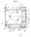
- FIG. 4 is a schematic plan view of relevant part of the image stabilizer 300.
- FIG. 5 is a cross section taken along line E-E' of FIG. 4 .
- FIG. 6 is a cross section taken along line A-A' of FIG. 4 .
- FIG. 7 is a cross section taken along line C-C' of FIG. 4 including a cross section taken along line D-D'.
- FIG. 8 is a cross section taken along line B-B' of FIG. 7 .
- the image stabilizer 300 shifts, as an object to be moved, the holder 35 (second movable member) having the CCD 31 mounted thereon in either or both the X-axis direction and the Y-axis direction.
- the image stabilizer 300 includes an X frame 301 and a frame (fixed member) 302.
- the X frame 301 includes a frame portion 301b that surrounds an opening 301a around the imaging optical axis.
- the X frame 301 movably supports the holder 35 in the Y-axis direction.
- the frame 302 includes a frame portion 302b that surrounds an opening 302a around the imaging optical axis.
- the frame 302 movably supports the X frame 301 in the X-axis direction and is fixed to the camera main body (not shown).
- the image stabilizer 300 further includes an X-axis drive mechanism 310x and a Y-axis drive mechanism 310y.
- the X-axis drive mechanism 310x moves the X frame 301 in the X-axis direction with respect to the frame 302.
- the Y-axis drive mechanism 310y moves the holder 35 in the Y-axis direction with respect to the X frame 301.
- the image stabilizer 300 shifts the holder 35 together with the X frame 301 in the X-axis direction with respect to the frame 302 as well as shifting the holder 35 in the Y-axis direction with respect to the X frame 301.
- the CCD 31 mounted on the holder 35 is shifted in either or both the X-axis direction and the Y-axis direction in the X-Y plane to correct for camera shake.
- the X-axis drive mechanism 310x includes an X-axis vibrator (first actuator) 320x, a slide member 330x, and a pressing mechanism 340x.
- the slide member 330x constitutes a first movable member 311x that is fixed to the X frame 301 and driven with the X frame 301.
- the pressing mechanism 340x biases the X-axis vibrator 320x to the side of the slide member 330x.
- the X-axis vibrator 320x includes a piezoelectric element 323x that has as a whole an elongated, rectangular shape. Following the operating principle of the vibrator 200 previously described in connection with FIG. 2 , the X-axis vibrator 320x generates elliptic vibration when applied with a predetermined frequency voltage in drivers (driving members) 321x and 322x which are arranged on one side of the piezoelectric element 323x.
- the X-axis vibrator 320x further includes a vibrator holder 324x at the center of the side of the piezoelectric element 323x opposite to the side where the drivers 321x and 322x are arranged.
- the vibrator holder 324x is provided with a protrusion 325x that is configured to fit in a groove (holding portion) 342x of the frame 302.
- the X-axis vibrator 320x is positioned and held such that its movement is regulated in the X-axis direction.
- a driving force due to elliptic vibration that occurs in the drivers 321x and 322x acts along the X-axis direction.
- the slide member 330x is formed of a bearing (guided member) 331x and a slide plate (sliding portion) 332x that is fixed to the bearing 331x.
- the bearing 331x is fixed to a portion of the X frame 301 with, for example, a screw 333x at a position where the drivers 321x and 322x on the piezoelectric element 323x are pressed into contact with the slide plate 332x.
- the bearing 331x is integrated with the X frame 301.
- the slide member 330x is smaller than the X frame 301. Specifically, the slide member 330x is equivalent in size to the X-axis vibrator 320x.
- the X frame 301 is made of a material such as low hardness resin or aluminum.
- the slide plate 332x is made of a material such as high hardness ceramic having wear resistance.
- the bearing 331x is made of a quenchable material such as ferrite stainless and is quenched to increase the hardness.
- the frame 302 includes an attachment portion in a form of opening and a bearing (guiding member) 304x.
- the bearing 304x is fixed to the attachment portion with a screw 303x to face the bearing 331x of the slide member 330x.
- a V-shaped groove 305x along the X-axis direction by fixing thereto a V-shaped groove plate 306x for wear protection.
- a V-shaped groove 334x on the bearing 331x is formed a V-shaped groove 334x by fixing thereto a V-shaped groove plate 335x for wear protection to be opposed to the V-shaped groove 305x (the V-shaped groove plate 306x).
- the rotating members need not necessarily be balls, and can be rollers.
- the pressing mechanism 340x includes a pressing plate 341x and a pressing spring 347x.
- One edge of the pressing plate 341x is fixed via a spacer 343x to the frame 302 with a screw 344x to support the X-axis vibrator 320x.
- the other edge of the pressing plate 341x is fixed to the frame 302 with a screw 345x.
- the pressing spring 347x is arranged around the screw 345x with a spacer 346x therebetween, and biases the pressing plate 341x so that the drivers 321x and 322x of the X-axis vibrator 320x are brought into pressure contact with the slide plate 332x.
- the pressure exerted by the pressing mechanism 340x is set to a high value of around 15 N (Newton).
- the bearing 331x is rotatable around an axis passing through the center of the balls 337x and 338x and in parallel with the V-shaped groove 334x, and is integrated with the X frame 301.
- a ball (rotating member) 307x is held by a biasing force of a spring 308x engaged between the X frame 301 and the frame 302, and is positioned to maintain a spacing in the imaging optical axis direction (the Z-axis direction) that the X frame 301 has with respect to the frame 302.
- the biasing force of the spring 308x is sufficient if capable of maintaining the ball 307x to be held, and is set to be smaller than that of the pressing spring 347x.
- the first movable member 311x formed of the X frame 301 and the slide member 330x is movable with respect to the frame 302 based on three-point support by the balls 337x, 338x, and 307x.
- the ball 307x is arranged opposite to the balls 337x and 338x with the imaging optical axis and the opening 301a therebetween. Accordingly, the ball 307x can be spaced apart from the balls 337x and 338x, which provides a stable three-point support structure.
- three balls (rotating members) guides the moving direction of the first movable member 311x as well as regulating the inclination thereof. Thus, stable driving operation can be achieved.
- the Y-axis drive mechanism 310y including a Y-axis vibrator (second actuator) 320y is of basically the same configuration as the X-axis drive mechanism 310x. Therefore, parts corresponding to those mentioned previously are identified by like reference numerals but with the addition of the suffix "y", and like description is not repeated.
- the Y-axis drive mechanism 310y includes a slide member 330y that constitutes a second movable member 311y.
- the second movable member 311y is integrally fixed to the holder 35, and is driven together with the holder 35.
- the image stabilizer 300 further includes an X-axis gyroscope 350x and a Y-axis gyroscope 350y on the frame 302.
- the X-axis gyroscope 350x detects camera shake around the X axis of the body unit 100 (in the pitch direction), while the Y-axis gyroscope 350y detects camera shake around the Y axis thereof (in the yaw direction).
- the image stabilizer 300 still further includes a position sensor 360, a vibrator drive circuit 354, and a vibration control circuit 355.
- the position sensor 360 detects a position of the CCD 31.
- the vibration control circuit 355 controls the vibrator drive circuit 354 for the X-axis vibrator 320x and the Y-axis vibrator 320y based on a signal from the X-axis gyroscope 350x, the Y-axis gyroscope 350y, and the position sensor 360.
- the X-axis drive mechanism 310x The operation of the X-axis drive mechanism 310x is described below.
- the X-axis vibrator 320x generates elliptic vibration in the drivers 321x and 322x when applied with a predetermined frequency voltage.
- the slide member 330x is driven in the direction of the elliptic vibration of the drivers 321x and 322x.
- the X-axis vibrator 320x is applied with high pressure, the drivers 321x and 322x are stably in pressure contact with the slide plate 332x because of the high hardness of the slide plate 332x and the bearing 331x. Accordingly, the driving force caused by the elliptic vibration is reliably transmitted to the slide plate 332x, and thus the slide member 330x can be efficiently driven in the direction of the elliptic vibration.
- the slide member 330x having the slide plate 332x is not in surface contact with the frame 302, but is in contact therewith via the rotating balls 337x and 338x at the bearings 331x and 304x. Therefore, even with high pressure, the slide member 330x reliably moves with low friction with respect to the frame 302.
- the bearings 331x and 304x have a ball bearing structure including balls placed in a row along the X-axis direction.
- the slide member 330x moves only in the X-axis direction.
- the X frame 301 having the slide member 330x fixed thereto also moves in the X-axis direction together with the slide member 330x.
- the moving direction of the X frame 301 is also guided by the engagement between the bearings 331x and 304x having a ball bearing structure in which balls are placed in a row along the X-axis direction.
- the bearing 331x is rotatable around an axis passing through the center of the balls 337x and 338x and in parallel with the V-shaped groove 334x.
- the bearing 331x is integrated with the X frame 301. Between the X frame 301 and the frame 302 is arranged the ball 307x in a position separate from the bearing 331x in a direction other than the X-axis direction.
- the first movable member 311x formed of the X frame 301 and the slide member 330x is supported with respect to the frame 302 based on three-point support by the balls 337x and 338x, and the ball 307x located separate from the balls 337x and 338x.
- the first movable member 311x stably moves on the frame 302 along the X-axis direction without being affected by the rotation around the axis in parallel with the V-shaped groove 334x. Therefore, a guide support mechanism for a portion where the X-axis vibrator 320x is applied with high pressure is only required to have the ball bearing structure of the bearings 331x and 304x that includes balls placed in a row along the X-axis direction. Thus, it is possible to downsize the electronic camera as well as to simplify the configuration of the camera.
- the Y-axis drive mechanism 310y operates basically in the same manner as the X-axis drive mechanism 310x.
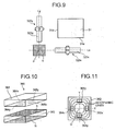
- FIG. 9 is a schematic diagram showing a positional relation between the X-axis vibrator 320x and the Y-axis vibrator 320y viewed from the rear side of the CCD 31.
- FIG. 10 is an enlarged perspective view of the position sensor 360 and a magnet.
- FIG. 11 is a front view for explaining a positional relation between the distribution of magnetic field lines of the magnet and arrangement of hall elements.
- FIG. 12 is plan view for explaining a positional relation between the distribution of the magnetic field lines of the magnet and arrangement of the hall elements.
- the X-axis vibrator 320x including the piezoelectric element 323x that has as a whole an elongated, rectangular shape is arranged near a first side (long side) 31a of the CCD 31 in parallel with the direction of the first side 31a (the X-axis direction).
- the Y-axis vibrator 320y including the piezoelectric element 323y that has as a whole an elongated, rectangular shape is arranged near a second side (short side) 31b of the CCD 31, which is perpendicular to the first side 31a, in parallel with the direction of the second side 31b (the Y-axis direction).
- the CCD 31 is formed in horizontally a little long rectangle with a ratio of the sides, for example, 4:3.
- the X-axis vibrator 320x is located at a position near intersection P of a longitudinal axis Lx of the X-axis vibrator 320x and a longitudinal axis Ly of the Y-axis vibrator 320y not to interfere with the Y-axis vibrator 320y.
- the Y-axis vibrator 320y is located at a position near the intersection P not to interfere with the X-axis vibrator 320x.
- the position sensor 360 detects the relative position of the CCD 31 shifted by the X-axis vibrator 320x and the Y-axis vibrator 320y. As shown in FIG. 9 , the position sensor 360 is located in a region E partly surrounded by an edge of the X-axis vibrator 320x and the Y-axis vibrator 320y and including the intersection P. As shown in FIGS. 4 and 5 , the position sensor 360 includes an arm 361, a magnet 362, and a detecting unit 363. The arm 361 extends from a portion of the holder 35 having the CCD 31 mounted thereon to the region E. The magnet 362 is attached to an end of the arm 361. The detecting unit 363 is supported by a supporting member 302c with respect to the frame 302, and faces the magnet 362 in the imaging optical axis direction in the region E.
- the detecting unit 363 includes a plurality of hall elements to detect a change in the magnetic force (magnetic flux density) of the magnet 362 in the region E.
- the detecting unit 363 includes four hall elements 364x, 365x, 364y, and 365y. As shown in FIGS. 10 and 11 , the hall elements 364x and 365x are located on an X axis, while the hall elements 364y and 365y are located on a Y axis.
- the X and Y axes correspond to the directions of the first side 31a and the second side 31b of the CCD 31, respectively.
- the magnet 362 is rectangular, and has a magnetic pole on each end (pole face) in the imaging optical axis direction (the z-axis direction), one called the north (N) pole and the other called the south (S) pole.
- N north
- S south
- magnetic field lines are symmetrically distributed around the magnet 362 such that they extend from the N pole to the S pole, and the magnetic field is maximum near the edges of the magnet 362.
- the magnet 362 exhibits isodynamic lines (distribution of equal magnetic flux density) pattern in substantially rectangular loops.
- the magnet 362 can be circular. In this case, the magnet 362 exhibits an isodynamic line pattern in concentric circles.
- the distribution of magnetic field lines is such that, when the X frame 301 and the holder 35 are located at substantially the center of the movement range, i.e., when the CCD 31 is located at a reference position where a travel distance thereof is 0 (zero), the center of the magnetic field lines matches the center O of the X axis and the Y axis.
- the hall elements 364x and 365x are arranged spaced apart from each other on the X axis, while the hall elements 364y and 365y are arranged spaced apart from each other on the Y axis.
- a magnetism detection plane as shown in FIG.
- the hall elements 364x and 365x are each arranged correspondingly to a magnetic flux density curving point inside a magnetic flux density maximum point, and symmetrically with respect to the center O.
- the hall elements 364y and 365y are each arranged correspondingly to a magnetic flux density curving point inside a magnetic flux density maximum point, and symmetrically with respect to the center O.
- the X-axis gyroscope 350x and the Y-axis gyroscope 350y detect camera shake
- either or both the X-axis vibrator 320x and the Y-axis vibrator 320y are driven by the vibrator drive circuit 354.
- the holder 35 having the CCD 31 mounted thereon is moved in either or both the X-axis direction and the Y-axis direction.
- the position sensor 360 detects whether the CCD 31 is shifted from the reference position to a desired position to compensate for the camera shake. The detection result is used for feedback control of the X-axis vibrator 320x and the Y-axis vibrator 320y.
- the arm 361 shifts the magnet 362 integrated with the holder 35 in the X-axis direction together with the holder 35.
- the hall elements 364x and 365x detects the same magnetic intensity when the CCD 31 is at the reference position. However, along with the movement of the holder 35 (the magnet 362), the magnetic intensity detected by the hall element 364x differs from that detected by the hall element 365x, one increases while the other decreases.
- a difference between the magnetic intensities detected by the hall elements 364x and 365x on the X axis is calculated as a damping ratio, and arithmetic processing is performed using a predetermined arithmetic expression.
- the feedback control of the X-axis vibrator 320x is performed in such a manner as to stop the movement of the CCD 31 when the relative position of the CCD 31 detected by the position sensor 360 reaches a desired position.
- the Y-axis vibrator 320y is driven and the holder 35 (the magnet 362) moves in the Y-axis direction, it is possible to accurately detect the angle of the CCD 31 and travel distance (relative position) thereof from the reference position in the Y-axis direction. Based on the detection result, the feedback control of the Y-axis vibrator 320y is performed in such a manner as to stop the movement of the CCD 31 when the relative position of the CCD 31 detected by the position sensor 360 reaches a desired position.
- the X-axis vibrator 320x and the Y-axis vibrator 320y are located at a position near the intersection P of the longitudinal axes Lx and Ly of them not to interfere with each other.
- the position sensor 360 detects the relative position of the CCD 31, and is located in the region E partly surrounded by an edge of the X-axis vibrator 320x and the Y-axis vibrator 320y and including the intersection P.
- the position sensor 360 can be arranged in a small dead space between the X-axis vibrator 320x and the Y-axis vibrator 320y. This achieves downsizing of the image stabilizer 300.
- the position sensor 360 can be arranged in the region E with no problem because the detecting unit 363 is formed integrally with the hall elements that detect magnetic fields in two directions, i.e., the X-axis and Y-axis directions, to be compact. Besides, the position sensor 360 can be arranged as close as possible to the CCD 31, which reduces errors superimposed in the detection system and thereby enables accurate detection of the relative position of the CCD 31. The position sensor 360 can also be arranged as close as possible to the X-axis vibrator 320x and the Y-axis vibrator 320y that control the position of the CCD 31.
- the movement of the CCD 31 moved through the X-axis vibrator 320x and the Y-axis vibrator 320y can be directly controlled.
- feedback control of the X-axis vibrator 320x and the Y-axis vibrator 320y can be appropriately performed.
- a couple of hall elements are provided on each of the X axis and the Y axis, and a difference between their detection results is calculated as a damping ratio. Based on the damping ratio, the relative position of the CCD 31 is detected.
- hall elements can be provided on the X and Y axes, one on each of them. In this case, the relative position of the CCD 31 is detected based on changes in magnetic intensity detected by the hall elements.
- the hall elements are illustrated as being arranged on the S-pole side of the magnet, they can be arranged on the N-pole side, or both the S-pole and N-pole sides. When the hall elements are arranged on both the S-pole and N-pole sides, the size of the region E shown in FIG. 9 can be reduced.
- FIGS. 13 to 15 depict a position sensor 370 employing an optical sensing system according to a modification of the embodiment.
- FIG. 13 is a cross section of relevant part of the image stabilizer taken along line C-C' of FIG. 4 corresponding to that of FIG. 7 .
- FIG. 14 is a front view for explaining a positional relation between a Y-axis sensor and a Y-axis scale.
- FIG. 15 is a front view for explaining a positional relation between an X-axis sensor and an X-axis scale.
- the position sensor 370 includes an X-axis sensor 371, an X-axis scale 372, a Y-axis sensor 373, and a Y-axis scale 374.
- the X-axis sensor 371 is arranged on the frame 302.
- the X-axis scale 372 is arranged on the X frame 301, and its travel distance is detected by the X-axis sensor 371.
- the Y-axis sensor 373 is arranged on the X frame 301.
- the Y-axis scale 374 is arranged on a supporting member 375 of the holder 35 having the CCD 31 mounted thereon, and its travel distance is detected by the Y-axis sensor 373.
- the X-axis sensor 371 and the Y-axis sensor 373 are each formed of a reflective optical sensor. On the X-axis scale 372 and the Y-axis scale 374, white and black tone patterns are formed at regular intervals with a predetermined pitch in the X-axis direction and the Y-axis direction, respectively.
- the X-axis sensor 371 and the Y-axis sensor 373 detect the number of the tone patterns from the reference position, based on which the position sensor 370 detects relative movement of the CCD 31 in the X-axis direction and the Y-axis direction.
- the X-axis sensor 371, the X-axis scale 372, the Y-axis sensor 373, and the Y-axis scale 374 are closely arranged in this order along the Z-axis direction in parallel with the imaging optical axis direction in the region E including the intersection P of the longitudinal axes Lx and Ly of the X-axis vibrator 320x and the Y-axis vibrator 320y.
- the X-axis scale 372 is formed in a size capable of covering its movement range with respect to the X-axis sensor 371.
- the Y-axis scale 374 is formed in a size capable of covering its movement range with respect to the X-axis sensor 371 as well as the Y-axis sensor 373.
- the position sensor 370 includes separate sensors for both the X-axis direction and the Y-axis direction, they are closely arranged in layers along the imaging optical axis direction in the region E. Therefore, the position sensor 370 can be arranged in the region E with no problem.
- the X-axis sensor 371 and the X-axis scale 372 are arranged close to each other, and also the Y-axis sensor 373 and the Y-axis scale 374 are arranged close to each other. This arrangement can improve the detection accuracy.
- the Y-axis scale 374 is formed in a size capable of covering its movement range with respect to not only the Y-axis sensor 373 but also the X-axis sensor 371, reliable detection can be ensured.
Landscapes
- Physics & Mathematics (AREA)
- Engineering & Computer Science (AREA)
- Multimedia (AREA)
- Signal Processing (AREA)
- General Physics & Mathematics (AREA)
- Optics & Photonics (AREA)
- Adjustment Of Camera Lenses (AREA)
- Studio Devices (AREA)
- Vehicle Body Suspensions (AREA)
- Length Measuring Devices By Optical Means (AREA)
Applications Claiming Priority (1)
| Application Number | Priority Date | Filing Date | Title |
|---|---|---|---|
| JP2007171059A JP2009008944A (ja) | 2007-06-28 | 2007-06-28 | ぶれ補正装置 |
Publications (2)
| Publication Number | Publication Date |
|---|---|
| EP2009909A2 true EP2009909A2 (fr) | 2008-12-31 |
| EP2009909A3 EP2009909A3 (fr) | 2011-11-30 |
Family
ID=39745029
Family Applications (1)
| Application Number | Title | Priority Date | Filing Date |
|---|---|---|---|
| EP08010633A Withdrawn EP2009909A3 (fr) | 2007-06-28 | 2008-06-11 | Stabilisateur d'image |
Country Status (4)
| Country | Link |
|---|---|
| US (1) | US7817908B2 (fr) |
| EP (1) | EP2009909A3 (fr) |
| JP (1) | JP2009008944A (fr) |
| CN (1) | CN101335492B (fr) |
Families Citing this family (16)
| Publication number | Priority date | Publication date | Assignee | Title |
|---|---|---|---|---|
| JP5284605B2 (ja) * | 2007-06-28 | 2013-09-11 | オリンパスイメージング株式会社 | 駆動装置及びぶれ補正装置 |
| JP5254904B2 (ja) * | 2009-08-20 | 2013-08-07 | キヤノン株式会社 | 撮像装置及び方法 |
| CN102789036A (zh) * | 2011-05-18 | 2012-11-21 | 亚洲光学股份有限公司 | 对焦机构 |
| JP5857322B2 (ja) * | 2011-06-02 | 2016-02-10 | 新シコー科技株式会社 | オートフォーカスカメラ及びカメラ付きモバイル端末装置 |
| WO2013035341A1 (fr) * | 2011-09-08 | 2013-03-14 | パナソニック株式会社 | Dispositif de détection de position, dispositif d'entraînement et tube de lentille |
| US9282224B2 (en) * | 2012-12-07 | 2016-03-08 | Samsung Electronics Co., Ltd. | Imaging apparatus having efficient dust removal apparatus and camera including the same |
| CN103175543B (zh) * | 2013-01-25 | 2015-06-24 | 中国科学院国家天文台 | 一种ccd像元内部响应差异的矫正方法 |
| CN104898349A (zh) * | 2015-06-30 | 2015-09-09 | 中山联合光电科技股份有限公司 | 一种镜头防抖装置 |
| CN106791289B (zh) * | 2015-11-20 | 2019-10-18 | 宁波舜宇光电信息有限公司 | 摄像模组及其光学防抖元件和防抖方法 |
| JP6655401B2 (ja) * | 2016-01-21 | 2020-02-26 | オリンパス株式会社 | 撮像装置、像ブレ補正方法 |
| US10575988B2 (en) * | 2017-10-12 | 2020-03-03 | Amo Development, Llc | Ophthalmic docking system with 3-dimensional automatic positioning using differential RF coupling |
| US10568765B2 (en) | 2017-10-17 | 2020-02-25 | Amo Development, Llc | Ophthalmic docking system with 3-dimensional automatic positioning using magnetic sensing array |
| CN108613661A (zh) * | 2018-06-04 | 2018-10-02 | 北京空间飞行器总体设计部 | 一种光学遥感卫星相机全光路像移测量系统 |
| JP7186047B2 (ja) | 2018-09-27 | 2022-12-08 | 日本電産サンキョー株式会社 | 振れ補正機能付きユニット |
| CN115427860B (zh) * | 2020-03-30 | 2024-03-29 | 三美电机株式会社 | 超声驱动装置、摄像机模块及摄像机搭载装置 |
| EP4099677A4 (fr) | 2021-04-14 | 2023-05-03 | Beijing Xiaomi Mobile Software Co., Ltd. | Actionneur de caméra |
Citations (1)
| Publication number | Priority date | Publication date | Assignee | Title |
|---|---|---|---|---|
| JP2006081348A (ja) | 2004-09-10 | 2006-03-23 | Konica Minolta Photo Imaging Inc | 駆動機構、振れ補正ユニット及びこれらを用いたカメラ |
Family Cites Families (13)
| Publication number | Priority date | Publication date | Assignee | Title |
|---|---|---|---|---|
| US7289212B2 (en) * | 2000-08-24 | 2007-10-30 | Asml Netherlands B.V. | Lithographic apparatus, device manufacturing method and device manufacturing thereby |
| US7436435B2 (en) * | 2001-10-01 | 2008-10-14 | Minolta Co., Ltd. | Image taking device having image-blur compensator |
| JP2005102172A (ja) * | 2003-08-21 | 2005-04-14 | Pentax Corp | 撮像装置 |
| JP2006078897A (ja) * | 2004-09-10 | 2006-03-23 | Konica Minolta Photo Imaging Inc | 撮像装置 |
| JP2006081006A (ja) * | 2004-09-10 | 2006-03-23 | Konica Minolta Photo Imaging Inc | 振れ補正機構付きカメラ |
| KR100630040B1 (ko) * | 2004-11-03 | 2006-09-27 | 삼성전자주식회사 | 카메라 렌즈 어셈블리의 손떨림 보정 장치 |
| JP2007065397A (ja) * | 2005-08-31 | 2007-03-15 | Olympus Imaging Corp | 鏡枠、電子撮像ユニットおよびカメラ |
| DE102006022336B8 (de) * | 2006-02-28 | 2015-12-31 | Infineon Technologies Ag | Magnetfeldsensor und Sensoranordnung mit demselben |
| JP4700555B2 (ja) * | 2006-05-02 | 2011-06-15 | 三星電子株式会社 | 像ぶれ補正装置 |
| US7893598B2 (en) * | 2006-12-15 | 2011-02-22 | Olympus Imaging Corp. | Driving apparatus and image pickup apparatus |
| JP4981484B2 (ja) * | 2007-03-02 | 2012-07-18 | オリンパスイメージング株式会社 | 駆動装置 |
| JP2008216570A (ja) * | 2007-03-02 | 2008-09-18 | Olympus Imaging Corp | 撮像装置 |
| US8575920B2 (en) * | 2007-12-05 | 2013-11-05 | Infineon Technologies Ag | Magneto-resistive magnetic field sensor |
-
2007
- 2007-06-28 JP JP2007171059A patent/JP2009008944A/ja active Pending
-
2008
- 2008-06-10 US US12/136,283 patent/US7817908B2/en not_active Expired - Fee Related
- 2008-06-11 EP EP08010633A patent/EP2009909A3/fr not_active Withdrawn
- 2008-06-27 CN CN2008101264622A patent/CN101335492B/zh not_active Expired - Fee Related
Patent Citations (1)
| Publication number | Priority date | Publication date | Assignee | Title |
|---|---|---|---|---|
| JP2006081348A (ja) | 2004-09-10 | 2006-03-23 | Konica Minolta Photo Imaging Inc | 駆動機構、振れ補正ユニット及びこれらを用いたカメラ |
Also Published As
| Publication number | Publication date |
|---|---|
| JP2009008944A (ja) | 2009-01-15 |
| CN101335492B (zh) | 2011-01-19 |
| US20090003812A1 (en) | 2009-01-01 |
| EP2009909A3 (fr) | 2011-11-30 |
| US7817908B2 (en) | 2010-10-19 |
| CN101335492A (zh) | 2008-12-31 |
Similar Documents
| Publication | Publication Date | Title |
|---|---|---|
| US7817908B2 (en) | Image stabilizer | |
| EP2009711B1 (fr) | Dispositif de commande et stabilisateur d'images | |
| US8928766B2 (en) | Anti-shake device for a lens module | |
| EP2009493B1 (fr) | Appareil de commande et appareil de capture d'images | |
| JP5230994B2 (ja) | 駆動装置および撮像装置 | |
| JP3728094B2 (ja) | 像ぶれ補正装置、光学機器、レンズ鏡筒および撮影装置 | |
| US8908086B2 (en) | Driving apparatus for shake correction and imaging apparatus using the same | |
| CN100501503C (zh) | 图像稳定器,透镜装置以及成像器装置 | |
| JP4981484B2 (ja) | 駆動装置 | |
| US7893598B2 (en) | Driving apparatus and image pickup apparatus | |
| JP2008216570A (ja) | 撮像装置 | |
| KR20130073465A (ko) | 카메라 모듈 | |
| JP5053985B2 (ja) | 駆動装置及びこの駆動装置を用いた撮像装置 | |
| US7884528B2 (en) | Driving apparatus | |
| JP5295836B2 (ja) | 像振れ補正装置、撮像レンズユニット、及びカメラユニット | |
| JP2008220030A (ja) | 駆動装置および撮像装置 | |
| JP2009265416A (ja) | 駆動装置および撮像装置 | |
| JP4951801B2 (ja) | アクチュエータ及びそれを備えたレンズユニット、カメラ | |
| JP2006330077A (ja) | 光学機器 | |
| KR20250171912A (ko) | 카메라 장치 및 광학기기 | |
| JPH11249191A (ja) | 像ぶれ補正装置 | |
| JP2008089805A (ja) | 撮像装置 | |
| JPH09244086A (ja) | 手振れ補正装置及びレンズ鏡筒付き手振れ補正装置 |
Legal Events
| Date | Code | Title | Description |
|---|---|---|---|
| PUAI | Public reference made under article 153(3) epc to a published international application that has entered the european phase |
Free format text: ORIGINAL CODE: 0009012 |
|
| 17P | Request for examination filed |
Effective date: 20080611 |
|
| AK | Designated contracting states |
Kind code of ref document: A2 Designated state(s): AT BE BG CH CY CZ DE DK EE ES FI FR GB GR HR HU IE IS IT LI LT LU LV MC MT NL NO PL PT RO SE SI SK TR |
|
| AX | Request for extension of the european patent |
Extension state: AL BA MK RS |
|
| PUAL | Search report despatched |
Free format text: ORIGINAL CODE: 0009013 |
|
| AK | Designated contracting states |
Kind code of ref document: A3 Designated state(s): AT BE BG CH CY CZ DE DK EE ES FI FR GB GR HR HU IE IS IT LI LT LU LV MC MT NL NO PL PT RO SE SI SK TR |
|
| AX | Request for extension of the european patent |
Extension state: AL BA MK RS |
|
| RIC1 | Information provided on ipc code assigned before grant |
Ipc: H04N 5/232 20060101AFI20111025BHEP |
|
| STAA | Information on the status of an ep patent application or granted ep patent |
Free format text: STATUS: THE APPLICATION HAS BEEN WITHDRAWN |
|
| 18W | Application withdrawn |
Effective date: 20120220 |