EP2009973A2 - Dispositif pour le contrôle d'un démarrage ou d'un arrêt doux de moteurs triphasés, le démarrage progressif - Google Patents
Dispositif pour le contrôle d'un démarrage ou d'un arrêt doux de moteurs triphasés, le démarrage progressif Download PDFInfo
- Publication number
- EP2009973A2 EP2009973A2 EP08011147A EP08011147A EP2009973A2 EP 2009973 A2 EP2009973 A2 EP 2009973A2 EP 08011147 A EP08011147 A EP 08011147A EP 08011147 A EP08011147 A EP 08011147A EP 2009973 A2 EP2009973 A2 EP 2009973A2
- Authority
- EP
- European Patent Office
- Prior art keywords
- power electronics
- power block
- power
- phase
- contactor
- Prior art date
- Legal status (The legal status is an assumption and is not a legal conclusion. Google has not performed a legal analysis and makes no representation as to the accuracy of the status listed.)
- Withdrawn
Links
- 239000007858 starting material Substances 0.000 title claims description 7
- 230000008878 coupling Effects 0.000 claims abstract description 15
- 238000010168 coupling process Methods 0.000 claims abstract description 15
- 238000005859 coupling reaction Methods 0.000 claims abstract description 15
- 210000002421 cell wall Anatomy 0.000 claims abstract description 5
- 210000004027 cell Anatomy 0.000 claims description 29
- 239000012212 insulator Substances 0.000 claims description 8
- 229910052782 aluminium Inorganic materials 0.000 claims description 6
- XAGFODPZIPBFFR-UHFFFAOYSA-N aluminium Chemical compound [Al] XAGFODPZIPBFFR-UHFFFAOYSA-N 0.000 claims description 6
- 239000011152 fibreglass Substances 0.000 claims description 5
- 239000003990 capacitor Substances 0.000 claims description 4
- RYGMFSIKBFXOCR-UHFFFAOYSA-N Copper Chemical compound [Cu] RYGMFSIKBFXOCR-UHFFFAOYSA-N 0.000 claims description 3
- 229910052802 copper Inorganic materials 0.000 claims description 3
- 239000010949 copper Substances 0.000 claims description 3
- 238000011144 upstream manufacturing Methods 0.000 claims description 2
- 238000003780 insertion Methods 0.000 abstract description 2
- 230000037431 insertion Effects 0.000 abstract description 2
- 230000001681 protective effect Effects 0.000 description 8
- 238000001816 cooling Methods 0.000 description 4
- 230000000712 assembly Effects 0.000 description 3
- 238000000429 assembly Methods 0.000 description 3
- 238000013461 design Methods 0.000 description 3
- 238000009434 installation Methods 0.000 description 3
- 239000011810 insulating material Substances 0.000 description 3
- 238000012423 maintenance Methods 0.000 description 3
- 239000004020 conductor Substances 0.000 description 2
- 238000010276 construction Methods 0.000 description 2
- 230000002349 favourable effect Effects 0.000 description 2
- 239000003365 glass fiber Substances 0.000 description 2
- 230000004308 accommodation Effects 0.000 description 1
- 230000002411 adverse Effects 0.000 description 1
- 238000011161 development Methods 0.000 description 1
- 238000004870 electrical engineering Methods 0.000 description 1
- 229910052751 metal Inorganic materials 0.000 description 1
- 239000002184 metal Substances 0.000 description 1
- 238000012986 modification Methods 0.000 description 1
- 230000004048 modification Effects 0.000 description 1
- 239000006870 ms-medium Substances 0.000 description 1
- 238000000926 separation method Methods 0.000 description 1
- 230000001502 supplementing effect Effects 0.000 description 1
- 238000012549 training Methods 0.000 description 1
- 230000000007 visual effect Effects 0.000 description 1
Images


Classifications
-
- H—ELECTRICITY
- H05—ELECTRIC TECHNIQUES NOT OTHERWISE PROVIDED FOR
- H05K—PRINTED CIRCUITS; CASINGS OR CONSTRUCTIONAL DETAILS OF ELECTRIC APPARATUS; MANUFACTURE OF ASSEMBLAGES OF ELECTRICAL COMPONENTS
- H05K7/00—Constructional details common to different types of electric apparatus
- H05K7/14—Mounting supporting structure in casing or on frame or rack
- H05K7/1422—Printed circuit boards receptacles, e.g. stacked structures, electronic circuit modules or box like frames
- H05K7/1427—Housings
- H05K7/1432—Housings specially adapted for power drive units or power converters
-
- H—ELECTRICITY
- H02—GENERATION; CONVERSION OR DISTRIBUTION OF ELECTRIC POWER
- H02P—CONTROL OR REGULATION OF ELECTRIC MOTORS, ELECTRIC GENERATORS OR DYNAMO-ELECTRIC CONVERTERS; CONTROLLING TRANSFORMERS, REACTORS OR CHOKE COILS
- H02P1/00—Arrangements for starting electric motors or dynamo-electric converters
- H02P1/16—Arrangements for starting electric motors or dynamo-electric converters for starting dynamo-electric motors or dynamo-electric converters
- H02P1/26—Arrangements for starting electric motors or dynamo-electric converters for starting dynamo-electric motors or dynamo-electric converters for starting an individual polyphase induction motor
- H02P1/28—Arrangements for starting electric motors or dynamo-electric converters for starting dynamo-electric motors or dynamo-electric converters for starting an individual polyphase induction motor by progressive increase of voltage applied to primary circuit of motor
-
- H—ELECTRICITY
- H05—ELECTRIC TECHNIQUES NOT OTHERWISE PROVIDED FOR
- H05K—PRINTED CIRCUITS; CASINGS OR CONSTRUCTIONAL DETAILS OF ELECTRIC APPARATUS; MANUFACTURE OF ASSEMBLAGES OF ELECTRICAL COMPONENTS
- H05K7/00—Constructional details common to different types of electric apparatus
- H05K7/14—Mounting supporting structure in casing or on frame or rack
- H05K7/1422—Printed circuit boards receptacles, e.g. stacked structures, electronic circuit modules or box like frames
- H05K7/1427—Housings
- H05K7/1432—Housings specially adapted for power drive units or power converters
- H05K7/14325—Housings specially adapted for power drive units or power converters for cabinets or racks
Definitions
- the invention relates to a device for controlling a soft start or run of three-phase motors (so-called soft starter), which are connected upstream for starting heavy mechanical, electrical or hydraulic drives, wherein individual modules of a power block with thyristors, power electronics and contactors in a control cabinet are summarized.
- Such devices operate in the power range of about 0.5 kW, in particular 200 kW to about 25000 kW and at rated voltages up to about 17.5 kV and currents up to about 1250 amperes.
- the design of such devices is known as a control cabinet.
- the disadvantages of this design consists in the arrangement of one or more cabinets in series and in the design inside the individual control cabinet.
- the power unit consists of per phase per block of thyristors with interconnected heat sinks, a protective circuit and an electronic control for the thyristors.
- the main power (power) connections are made only from above or below, or from above and below. In practical cases, this results in a minimum distance (of approx. 120 mm) depending on the voltage level.
- Such cabinets can only be set up individually. A series of such cabinets would adversely occupy a large space that can not otherwise be used. Such cabinets can only be set up individually. A row next to each other Switch cabinets would disadvantageously occupy a large space. This results in an enormous space requirement for the other components and assemblies required for the circuit of the soft starter.
- the invention has for its object, essential components and assemblies, such as the mains contactor, the power electronics L1, L2 and L3 and the bypass contactor both for a single and a series installation of the cabinet or the switching cells of different power levels with an improved Room layout to be arranged taking into account special maintenance conditions.
- a cabinet at least one switching cell is formed, which comprises at least the 3-phase power block, the associated power electronics and the required contactors and in a frame with surrounding switching cell walls and an attachment extending in the direction of construction post insulators as a unit front slightly expandable or vice versa installed and without attachment to a back or side wall of the cabinet is arranged and that in contrast a mounted on the cabinet wall disconnector with a busbar connection by means of a plug-in contact coupling when inserted connectable or detachable during extension (embodiment "A" / Fig. 1A ).
- the advantages are easy and safe maintenance outside the cabinet and a more favorable floor plan in so far as the width of the cabinet is reduced overall and therefore creates a smaller width in a single and with the number of juxtaposed cabinets increasing space gain.
- the power block (per phase) with associated components is therefore summarized or arranged without attachment to the rear wall or the side walls of the cabinet. in the Compared to the previously known embodiment, this summary of the components to a power block is only possible if the power electronics as known not with the power electronics constructively supporting the rear wall to the control cabinet rear wall is installed.
- the three power electronics (one piece per phase) in Isolierstoff Eisen Eisenierstoff Eisenierstoff Eisenn from the known construction rotated by 180 ° each with the supporting glass fiber reinforced rear wall to the cabinet front, installed in the frame and attached to trusses.
- one or more mainstream connections can be routed through the load-bearing glass-fiber reinforced rear walls of the power electronics or past the top and bottom of the rear wall to bypassing contactors located in front of them or to a main contactor.
- bypassing contactors located in front of them or to a main contactor.
- the use of an aluminum heat sink as a conductive connecting element in the power electronics is advantageous.
- the known cabinets can be built up to 50% narrower due to the invention.
- a more extensive equipment arises according to further features in that in the frame of the switching cell in the three-phase motor cables single or double fuses, surge arresters and voltage sensors and / or current sensors are arranged and that each one attached to the cabinet wall busbars Connection is connectable or detachable by means of a second plug-in contact coupling (embodiment "C" / FIG. 1 B) ,
- the installation or removal of the switching cell is particularly simple and can be accomplished in a short time, if at least the power electronics is arranged in a retractable from the cabinet or trolley according to further features and in such a case, the power block is held stationary.
- the complete switching cell can also be easily accessible from all sides, if the power block and the power block are arranged at operating distance on the car next to the power electronics.
- At least one rear wall for the power electronics is formed on the trolley made of glass fiber reinforced plastic.
- An improvement is also that between a removable insulating plate and open contacts of the circuit breaker and a downstream power contactor for each phase a double-fuse is connected.
- a grounding bolt is connected in front of the output of the 3-phase line from the insulated housing.
- the power block be connected at the bottom to the bypass contactor and at the top to the contactor.
- a detachable contact screw connection for a capacitor is provided on the power block.
- bridging contactor is connected in each case by means of the main electrical current leading copper busbars in the power block to aluminum heat sink of the power electronics, which can be connected via the contact coupling with the busbar for the motor connection.
- the invention also relates to safety aspects in the operation of the device and designed this further characterized by the fact that the circuit breaker by means of a shaft and the earthing switch are also actuated by means of a shaft from the outside of the cabinet.
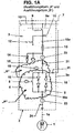
- Fig. 1A is connected to a cabinet 2 gently cranked three-phase motor 1 via a corresponding guided 3-phase line 1a.
- a switching cell 3 with all the main components, namely a (yet to be explained) power block 4, consisting of several power electronics 5, an electronic control 29 and a protective circuit 30 ( Fig. 3 )
- a bypass contactor 6 is formed, which has an openly accessible after expansion frame 7.
- the frame 7 has functionally a back or side wall 8 ( Fig. 2 ).
- the circuit can be earthed with a grounding switch 12.
- Between the open contacts of the circuit breaker 9 is an insulating material 9a through the slot 36 (FIG. Fig. 3 ) inserted.
- the electrical elements can be switched off or switched on from outside by means of the circuit breaker 9, which consists of a (dot-dashed line) insulating plate 9a with the width of the slot 36.
- a busbar terminal 10 In the area of the circuit breaker 9 is a busbar terminal 10 and in succession a capacitive voltage indicator 11 having a ground 12.
- fuses 13 are provided. This is followed by a surge arrester 14.
- a surge arrester 14 Connected thereto are voltage sensors 15.
- the main contactor 18 is connected before the power block 4, which is formed from the thyristors 16 with interposed aluminum cooling plates 17 (see. Fig. 2 to 4 ).
- the main contactor 18 Before the power block 4, which is formed from the thyristors 16 with interposed aluminum cooling plates 17 (see. Fig. 2 to 4 ), the main contactor 18 is connected. The latter is located in a condenser control panel 21 and is protected from a capacitor 22 by means of double fuses 13.
- the embodiment "A” shows in three-side-by-side arrangement each enclosed on four sides, open top and bottom for cooling housing made of fiberglass reinforced plastic, which encloses the following components: the power electronics 5, the thyristors 16, the electronic control 29 for the thyristors 16, the protective circuit 30 for the thyristors 16, a bypass contactor 6, a contact coupling 10a and a detachable Kunststoffschraub für 31st
- Fig. 1B is to Fig. 1A an alternative embodiment "C" shown.
- the higher-lying components eg. 11, 12, etc. are already fixed and belong to the assembly of non-expandable Disconnect switch 9.
- This embodiment "C” in turn shows in three-side-by-side arrangement enclosed on four sides, open top and bottom for cooling housing made of fiberglass reinforced plastic enclosing the following components:
- the switching cell 3 is supported by a frame 7 designed as a carriage 25 and on pairs of wheels 25 a, 25 b from and into the cabinet 2 in Arrow directions 26 movable.
- the circuit breaker 9 is fixedly arranged on the control cabinet 2 for the 3-phase line 1a.
- the busbar 27 for the motor connection by means of support insulators 28 on the control cabinet 2 and indeed attached to the rear or side wall 8.
- Such insulating holder 28 are provided on the entire switching cell unit 3 for fixing the current conductor.
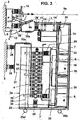
- Fig. 3 are the assemblies made Fig. 2 seen in the plane from the side, in turn, the at the cabinet 2, ie at the back or side wall 8, fixed disconnect switch 9 (with the not shown there switching shaft 34 as a manual switching element, which is guided through the cabinet 2 through to the outside) and the busbar 27 are visible for the connection of the three-phase motor 1 to be started.
- the circuit breaker 9 is drawn in the open position.
- the frame 7 as a carrier for the actual switching cell 3 is in training as a cart 25 with the pairs of wheels 25a, 25b by means of the respective contact couplings 10a both of the busbar 27 and the disconnector 9 disengaged and is driven to the maintenance of the cabinet 2 and after completed Service back again and reconnected via the contact couplings 10a.
- a respective laterally arranged parallelogram lever arrangement for swiveling out the switching cell 3 from the control cabinet 2 and for re-pivoting can be used.
- Between the lined-up thyristors 16 are each aluminum cooling plates 17.
- the electronic control 29 for the thyristors 16 and the protective circuit 30 are provided for the thyristors 16. These are located within the power block 4.
- the surge arrester 14 belongs to the switching cell 3.
- the disconnect switch 9, the busbar terminal 10 is visible for each phase.
- This embodiment “C” is in turn characterized by the triple sidelobe arrangement of the four-sided enclosing, top and bottom open housing made of fiberglass reinforced plastic, which encloses the following components: The power electronics 5, the thyristors 16, the electronic control 29 for the thyristors, the protective circuit 30 for the thyristors, the bypass contactor 6, the contact coupling 10a, the main contactor 18, a double fuse 13, a surge arrester 14, a voltage sensor 15, a (capacitive) voltage indicator 11, post insulators 28 and another contact coupling 10a.
- the contactors 6, 18 can also be replaced by circuit breakers while maintaining the spatial arrangement in the power block 4.
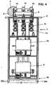
- Fig. 4 shows the cabinet 2 in or opposite (parallel) to the direction of travel in the direction of arrows 26.
- the in the Fig. 1A to 3 shown components are therefore already visible and described.
- the switching cell 3 as a carriage 25 has only a small width 32, because the space requirement could be significantly reduced by favorable arrangement of all units.
- Within the cabinet 2 is located on the back wall 8, only the fixed circuit breaker 9 with the busbar terminals 10 for the three phases.
- the switching cell frame 3a is the largest width dimension. The switching cell 3 receives therein the double fuses 13.
- the switching cell 3 is designed here as a carriage 25 and has the pairs of wheels 25a and 25b. Previous control cabinets 2 can be built on the basis of the invention with up to 50% space savings.
- Fig. 5 is the control cabinet 2 from the outside manageable, the busbar terminals 10 of the power supply protrude to the right. Further, the shaft 34 for the operation of the circuit breaker 9 (in Fig. 3 located inside) out and can be operated from there. Similarly, a shaft 35 is guided for the earthing switch 12 to the outside and can also be operated from there become.
- a safeguard against unintentional closing of the circuit breaker 9 by means of the insulating plate 9a takes place in that the insulating plate 9a passes through the slot 36 and is pushed between the open contacts of the circuit breaker 9.
- Fig. 3 is a switch blade 9b shown in phantom in the closed position.
- the area of the disconnector 9 forms a low-voltage space NS.
- the space NS is hermetically separated from the area of a medium-voltage space MS by sheet metal walls, ie, it is partitioned. The latter serves to accommodate the components belonging to the main circuit (cf. Fig. 1A . 1B . Fig. 3 and Fig. 4 ).
- the circuit breaker 9 can only be turned on when the earthing switch 12 is turned off, that is open.
- the opening of the door in front of the medium-voltage space MS is also mechanically locked.
- the operator inserted through the slot 36 on the front of the cabinet 2, the insulating plate 9a deep into the switch cell 3 into the open contacts of the disconnector 9. Only after opening the circuit breaker 9, the closing of the earthing switch 12 and the insertion of the insulating material 9a, the operator can open the door to the medium-voltage space MS.
- These mechanical interlocks ensure for the operator that no incorrect operation occurs. Of the Condition is ensured by the visual and safe separation distance of the busbar leading to the voltage, the grounded state of the components in the medium-voltage space MS of the switching cell 3 below the circuit breaker 9.
Landscapes
- Engineering & Computer Science (AREA)
- Power Engineering (AREA)
- Microelectronics & Electronic Packaging (AREA)
- Patch Boards (AREA)
- Motor And Converter Starters (AREA)
Applications Claiming Priority (1)
| Application Number | Priority Date | Filing Date | Title |
|---|---|---|---|
| DE102007030344A DE102007030344B4 (de) | 2007-06-29 | 2007-06-29 | Einrichtung für die Kontrolle eines sanften Anlaufs oder Auslaufs von Drehstrommotoren, - sog. Soft-Starter |
Publications (2)
| Publication Number | Publication Date |
|---|---|
| EP2009973A2 true EP2009973A2 (fr) | 2008-12-31 |
| EP2009973A3 EP2009973A3 (fr) | 2010-05-19 |
Family
ID=39810317
Family Applications (1)
| Application Number | Title | Priority Date | Filing Date |
|---|---|---|---|
| EP08011147A Withdrawn EP2009973A3 (fr) | 2007-06-29 | 2008-06-19 | Dispositif pour le contrôle d'un démarrage ou d'un arrêt doux de moteurs triphasés, le démarrage progressif |
Country Status (6)
| Country | Link |
|---|---|
| US (1) | US7948203B2 (fr) |
| EP (1) | EP2009973A3 (fr) |
| JP (1) | JP2009017774A (fr) |
| CN (1) | CN101355331A (fr) |
| DE (1) | DE102007030344B4 (fr) |
| RU (1) | RU2382459C1 (fr) |
Cited By (3)
| Publication number | Priority date | Publication date | Assignee | Title |
|---|---|---|---|---|
| CN101976992A (zh) * | 2010-09-15 | 2011-02-16 | 江苏三上机电制造股份有限公司 | 施工升降机软启动控制系统 |
| EP2775606A4 (fr) * | 2011-10-31 | 2015-08-12 | Fuji Electric Co Ltd | Dispositif inverseur |
| WO2018172049A1 (fr) * | 2017-03-20 | 2018-09-27 | Abb Schweiz Ag | Redresseur à diodes extractible |
Families Citing this family (17)
| Publication number | Priority date | Publication date | Assignee | Title |
|---|---|---|---|---|
| RU2421874C1 (ru) * | 2010-04-26 | 2011-06-20 | Открытое акционерное общество "Всероссийский научно-исследовательский проектно-конструкторский и технологический институт релестроения с опытным производством" | Устройство для плавного пуска группы электродвигателей |
| DE102011001731A1 (de) * | 2011-04-01 | 2012-10-04 | Igel Elektronik Gmbh | Vorrichtung zum Sanftanlauf |
| CN102811005B (zh) * | 2011-05-30 | 2015-11-25 | 上海雷诺尔科技股份有限公司 | 抽出式中压固态软起动器 |
| JP5782995B2 (ja) | 2011-10-31 | 2015-09-24 | 富士電機株式会社 | インバータ装置 |
| US20140118907A1 (en) * | 2012-11-01 | 2014-05-01 | Cooper Technologies Company | Dielectric Insulated Capacitor Bank |
| CN105453325A (zh) * | 2013-07-29 | 2016-03-30 | 东莞乔登节能科技有限公司 | 电极片、电极片的成型方法及具有该电极片的锂电池芯成型方法 |
| US20150048690A1 (en) * | 2013-08-15 | 2015-02-19 | Solcon Industries Ltd. | Medium voltage power controller |
| CN103944070B (zh) * | 2014-04-11 | 2016-03-09 | 都匀供电局 | 简易过电压保护装置 |
| CN104300414B (zh) * | 2014-11-14 | 2018-11-27 | 泰兴市赛尔新能源科技有限公司 | 一种能除湿的抽屉式电力控制柜组件 |
| CN104332877B (zh) * | 2014-11-14 | 2018-10-16 | 福建庆烨电子有限公司 | 一种带有照明装置的抽屉式电力控制柜组件 |
| CN105141118B (zh) * | 2015-08-26 | 2017-12-15 | 大力电工襄阳股份有限公司 | 中压晶闸管软起动模块 |
| FR3044842B1 (fr) * | 2015-12-02 | 2021-12-03 | Valeo Systemes De Controle Moteur | Architecture electronique destinee a alimenter une machine electrique pour vehicule automobile |
| CN106410646B (zh) * | 2016-11-07 | 2018-02-06 | 河钢股份有限公司邯郸分公司 | 一种交直交高压变频器的故障快速判断和处理操作方法 |
| DE102017004221A1 (de) * | 2017-05-03 | 2018-11-08 | Thyssenkrupp Ag | Elektrische Baugruppe |
| KR102064110B1 (ko) * | 2019-04-12 | 2020-01-08 | 한전케이피에스 주식회사 | 구조 변경이 가능한 인버터 스택 |
| CN117136491A (zh) * | 2021-04-01 | 2023-11-28 | 三菱电机株式会社 | 功率转换装置 |
| US12463455B2 (en) * | 2022-12-09 | 2025-11-04 | Fuji Electric Co., Ltd. | Uninterruptible power supply device and control module for uninterruptible power supply device |
Citations (5)
| Publication number | Priority date | Publication date | Assignee | Title |
|---|---|---|---|---|
| DE1790184B2 (de) | 1968-09-25 | 1973-12-13 | Siemens Ag, 1000 Berlin U. 8000 Muenchen | Lichtbogenfeste Hochspannungs schaltzelle Ausscheidung in 1790295 |
| EP0263396A1 (fr) | 1986-10-10 | 1988-04-13 | Siemens Aktiengesellschaft | Chariot extractible pour un tableau électrique blindé |
| DE69115311T2 (de) | 1990-03-16 | 1996-07-18 | Allen Bradley Co | Steuergerät für einen Elektromotor mit Überbrückungsschaltschütz |
| DE10301270A1 (de) | 2002-01-17 | 2003-07-31 | Abb Technology Ag Zuerich | Trennschalter für die Installierung in einem Schaltvorrichtungsgehäuse |
| WO2006034977A1 (fr) | 2004-09-28 | 2006-04-06 | Siemens Aktiengesellschaft | Procede pour determiner et specifier des parametres d'un appareil de commande electronique moteur et positionneur triphase a parametrage automatique associe, en particulier demarreur progressif |
Family Cites Families (14)
| Publication number | Priority date | Publication date | Assignee | Title |
|---|---|---|---|---|
| DE698230C (de) * | 1938-02-12 | 1940-11-05 | Aeg | Elektrische Hochspannungsschaltanlage der Zellenbauweise |
| DE971607C (de) * | 1952-08-13 | 1959-02-26 | Voigt & Haeffner Ag | Anordnung fuer fahrbare, mit Transportrollen versehene elektrische Schaltwagen, insbesondere fuer blechgekapselte Hochspannungs-Schaltanlagen |
| BE754943A (fr) * | 1969-08-27 | 1971-02-01 | Siemens Ag | Dispositf de commande electrique pour moteurs |
| US4638226A (en) * | 1985-02-07 | 1987-01-20 | Eaton Corporation | Speed control system with feedback and soft-start |
| US4768967A (en) * | 1987-06-26 | 1988-09-06 | Eaton Corporation | Latch for removable control unit of a motor control center |
| DE9111663U1 (de) * | 1990-11-20 | 1991-11-14 | Siemens AG, 80333 München | Einschubteil mit Frontabdeckung |
| DE19653831A1 (de) * | 1996-12-21 | 1998-06-25 | Bosch Gmbh Robert | Elektrisches Gerät |
| US6208111B1 (en) * | 1997-10-21 | 2001-03-27 | Kevin R. Williams | Motor starter arrangement with soft start electronic control |
| DE19938795C2 (de) * | 1999-08-16 | 2002-02-28 | All Systems Go Ges Fuer Medien | Verschlußmechanismus und dessen Verwendung |
| RU23912U1 (ru) * | 2002-02-18 | 2002-07-20 | Закрытое акционерное общество "Электон" | Станция управления погружными электронасосами |
| JP4352762B2 (ja) * | 2003-05-27 | 2009-10-28 | 三菱電機株式会社 | 電力変換装置 |
| US7525809B2 (en) * | 2003-09-30 | 2009-04-28 | Rockwell Automation Technologies, Inc. | Isolated control and network wireway for motor control center |
| RU37577U1 (ru) * | 2003-11-18 | 2004-04-27 | Центр Разработки Нефтедобывающего Оборудования | Шкаф станции управления асинхронным двигателем центробежного погружного насоса и силовой отсек шкафа станции управления асинхронным двигателем центробежного погружного насоса |
| US7419394B2 (en) * | 2005-11-11 | 2008-09-02 | Rockwell Automation Technologies, Inc. | Electrical system having withdrawable unit with maintained control and communication connection |
-
2007
- 2007-06-29 DE DE102007030344A patent/DE102007030344B4/de not_active Expired - Fee Related
-
2008
- 2008-06-19 EP EP08011147A patent/EP2009973A3/fr not_active Withdrawn
- 2008-06-23 RU RU2008124959/09A patent/RU2382459C1/ru not_active IP Right Cessation
- 2008-06-23 US US12/214,847 patent/US7948203B2/en not_active Expired - Fee Related
- 2008-06-26 CN CNA2008101305209A patent/CN101355331A/zh active Pending
- 2008-06-26 JP JP2008167182A patent/JP2009017774A/ja active Pending
Patent Citations (5)
| Publication number | Priority date | Publication date | Assignee | Title |
|---|---|---|---|---|
| DE1790184B2 (de) | 1968-09-25 | 1973-12-13 | Siemens Ag, 1000 Berlin U. 8000 Muenchen | Lichtbogenfeste Hochspannungs schaltzelle Ausscheidung in 1790295 |
| EP0263396A1 (fr) | 1986-10-10 | 1988-04-13 | Siemens Aktiengesellschaft | Chariot extractible pour un tableau électrique blindé |
| DE69115311T2 (de) | 1990-03-16 | 1996-07-18 | Allen Bradley Co | Steuergerät für einen Elektromotor mit Überbrückungsschaltschütz |
| DE10301270A1 (de) | 2002-01-17 | 2003-07-31 | Abb Technology Ag Zuerich | Trennschalter für die Installierung in einem Schaltvorrichtungsgehäuse |
| WO2006034977A1 (fr) | 2004-09-28 | 2006-04-06 | Siemens Aktiengesellschaft | Procede pour determiner et specifier des parametres d'un appareil de commande electronique moteur et positionneur triphase a parametrage automatique associe, en particulier demarreur progressif |
Non-Patent Citations (1)
| Title |
|---|
| AUCOM - CATALOGUE - DATA - MVS Series Medium Voltage Soft Starters |
Cited By (4)
| Publication number | Priority date | Publication date | Assignee | Title |
|---|---|---|---|---|
| CN101976992A (zh) * | 2010-09-15 | 2011-02-16 | 江苏三上机电制造股份有限公司 | 施工升降机软启动控制系统 |
| CN101976992B (zh) * | 2010-09-15 | 2012-05-16 | 江苏三上机电制造股份有限公司 | 施工升降机软启动控制系统 |
| EP2775606A4 (fr) * | 2011-10-31 | 2015-08-12 | Fuji Electric Co Ltd | Dispositif inverseur |
| WO2018172049A1 (fr) * | 2017-03-20 | 2018-09-27 | Abb Schweiz Ag | Redresseur à diodes extractible |
Also Published As
| Publication number | Publication date |
|---|---|
| US20090015190A1 (en) | 2009-01-15 |
| EP2009973A3 (fr) | 2010-05-19 |
| JP2009017774A (ja) | 2009-01-22 |
| US7948203B2 (en) | 2011-05-24 |
| CN101355331A (zh) | 2009-01-28 |
| DE102007030344A1 (de) | 2009-01-02 |
| DE102007030344B4 (de) | 2009-10-15 |
| RU2008124959A (ru) | 2009-12-27 |
| RU2382459C1 (ru) | 2010-02-20 |
Similar Documents
| Publication | Publication Date | Title |
|---|---|---|
| DE102007030344B4 (de) | Einrichtung für die Kontrolle eines sanften Anlaufs oder Auslaufs von Drehstrommotoren, - sog. Soft-Starter | |
| DE3715053C2 (fr) | ||
| DE69221265T2 (de) | SFG-Lasttrennschalter und Verwendung in Zellen und Posten und vorfabrizierten Unterstationen | |
| DE102010013877B4 (de) | Elektrischer Leistungsschalter und Schaltfeld mit Leistungsschalter | |
| EP1463174B1 (fr) | Appareillage de commutation blindé métallique à isolement gazeux | |
| WO2007137976A1 (fr) | Panneau de distribution pour installations de distribution électriques moyenne tension | |
| DE68904362T2 (de) | Gekapselte station fuer hochspannung mit zweifachversorgung. | |
| DE19523592C2 (de) | Niederspannungs-Schaltgeräte-Kombination | |
| EP0878816A2 (fr) | Disjoncteur dans un boítier métallique isolé par gaz | |
| EP3488457A1 (fr) | Dispositif et procédé de commutation de moyennes et hautes tensions | |
| DE19631817C1 (de) | SF¶6¶-gasisolierte Schaltanlage für Verteilernetze | |
| CH694417A5 (de) | Gasisolierte, dreiphasig gekapselte Schaltanlage. | |
| EP1251615A2 (fr) | Cellule de commutation haute-tension | |
| DE3873677T2 (de) | Mittelspannungsfertigschalttafel mit drehschalter. | |
| DE1540176A1 (de) | Gekapselte Umschalteinrichtung fuer mittlere oder hohe Spannung | |
| DE19807777C1 (de) | Schaltfeld für eine gasisolierte Schaltanlage mit liegenden Leistungsschaltern und einer einseitig zu einer vertikalen Strombahn angeordneten dreiphasig gekapselten Doppelsammelschiene | |
| DE2856187C2 (de) | Mehrpolige Umschalteinrichtung für Mittelspannungsschaltfelder | |
| EP1463171A1 (fr) | Cellule de commutation haute-tension | |
| RU34811U1 (ru) | Устройство комплектное распределительное серии К-121 | |
| DE29510513U1 (de) | Niederspannungs-Schaltgeräte-Kombination | |
| AT228323B (de) | Vorgefertigte durch Steckverbindungen schaltbare elektrische Schaltzelle | |
| WO2022096078A1 (fr) | Tableau de commutation pour appareillage de commutation extérieur | |
| DE4126786A1 (de) | Elektrische schaltvorrichtung | |
| DE19839318A1 (de) | Elektrische Schaltfeldanordnung und luftisolierte Schaltanlage | |
| AT374980B (de) | Einrichtung zur umgehung eines hochspannungsleistungsschalters |
Legal Events
| Date | Code | Title | Description |
|---|---|---|---|
| PUAI | Public reference made under article 153(3) epc to a published international application that has entered the european phase |
Free format text: ORIGINAL CODE: 0009012 |
|
| 17P | Request for examination filed |
Effective date: 20080911 |
|
| AK | Designated contracting states |
Kind code of ref document: A2 Designated state(s): AT BE BG CH CY CZ DE DK EE ES FI FR GB GR HR HU IE IS IT LI LT LU LV MC MT NL NO PL PT RO SE SI SK TR |
|
| AX | Request for extension of the european patent |
Extension state: AL BA MK RS |
|
| PUAL | Search report despatched |
Free format text: ORIGINAL CODE: 0009013 |
|
| AK | Designated contracting states |
Kind code of ref document: A3 Designated state(s): AT BE BG CH CY CZ DE DK EE ES FI FR GB GR HR HU IE IS IT LI LT LU LV MC MT NL NO PL PT RO SE SI SK TR |
|
| AX | Request for extension of the european patent |
Extension state: AL BA MK RS |
|
| AKX | Designation fees paid |
Designated state(s): AT BE BG CH CY CZ DE DK EE ES FI FR GB GR HR HU IE IS IT LI LT LU LV MC MT NL NO PL PT RO SE SI SK TR |
|
| TPAC | Observations filed by third parties |
Free format text: ORIGINAL CODE: EPIDOSNTIPA |
|
| STAA | Information on the status of an ep patent application or granted ep patent |
Free format text: STATUS: THE APPLICATION IS DEEMED TO BE WITHDRAWN |
|
| 18D | Application deemed to be withdrawn |
Effective date: 20120103 |