EP2010352B1 - Siebdruckkopfssystem und Verfahren zum Drucken mittels eines Siebdruckkopfes - Google Patents
Siebdruckkopfssystem und Verfahren zum Drucken mittels eines Siebdruckkopfes Download PDFInfo
- Publication number
- EP2010352B1 EP2010352B1 EP07732343.4A EP07732343A EP2010352B1 EP 2010352 B1 EP2010352 B1 EP 2010352B1 EP 07732343 A EP07732343 A EP 07732343A EP 2010352 B1 EP2010352 B1 EP 2010352B1
- Authority
- EP
- European Patent Office
- Prior art keywords
- print medium
- cavity
- optionally
- chamber
- Prior art date
- Legal status (The legal status is an assumption and is not a legal conclusion. Google has not performed a legal analysis and makes no representation as to the accuracy of the status listed.)
- Active
Links
Images






Classifications
-
- B—PERFORMING OPERATIONS; TRANSPORTING
- B05—SPRAYING OR ATOMISING IN GENERAL; APPLYING FLUENT MATERIALS TO SURFACES, IN GENERAL
- B05D—PROCESSES FOR APPLYING FLUENT MATERIALS TO SURFACES, IN GENERAL
- B05D1/00—Processes for applying liquids or other fluent materials
- B05D1/26—Processes for applying liquids or other fluent materials performed by applying the liquid or other fluent material from an outlet device in contact with, or almost in contact with, the surface
-
- B—PERFORMING OPERATIONS; TRANSPORTING
- B23—MACHINE TOOLS; METAL-WORKING NOT OTHERWISE PROVIDED FOR
- B23K—SOLDERING OR UNSOLDERING; WELDING; CLADDING OR PLATING BY SOLDERING OR WELDING; CUTTING BY APPLYING HEAT LOCALLY, e.g. FLAME CUTTING; WORKING BY LASER BEAM
- B23K3/00—Tools, devices or special appurtenances for soldering, e.g. brazing, or unsoldering, not specially adapted for particular methods
- B23K3/06—Solder feeding devices; Solder melting pans
- B23K3/0607—Solder feeding devices
- B23K3/0638—Solder feeding devices for viscous material feeding, e.g. solder paste feeding
-
- B—PERFORMING OPERATIONS; TRANSPORTING
- B05—SPRAYING OR ATOMISING IN GENERAL; APPLYING FLUENT MATERIALS TO SURFACES, IN GENERAL
- B05D—PROCESSES FOR APPLYING FLUENT MATERIALS TO SURFACES, IN GENERAL
- B05D1/00—Processes for applying liquids or other fluent materials
- B05D1/32—Processes for applying liquids or other fluent materials using means for protecting parts of a surface not to be coated, e.g. using stencils, resists
-
- B—PERFORMING OPERATIONS; TRANSPORTING
- B05—SPRAYING OR ATOMISING IN GENERAL; APPLYING FLUENT MATERIALS TO SURFACES, IN GENERAL
- B05D—PROCESSES FOR APPLYING FLUENT MATERIALS TO SURFACES, IN GENERAL
- B05D1/00—Processes for applying liquids or other fluent materials
- B05D1/40—Distributing applied liquids or other fluent materials by members moving relatively to surface
-
- B—PERFORMING OPERATIONS; TRANSPORTING
- B41—PRINTING; LINING MACHINES; TYPEWRITERS; STAMPS
- B41F—PRINTING MACHINES OR PRESSES
- B41F15/00—Screen printers
- B41F15/14—Details
- B41F15/40—Inking units
- B41F15/42—Inking units comprising squeegees or doctors
-
- G—PHYSICS
- G03—PHOTOGRAPHY; CINEMATOGRAPHY; ANALOGOUS TECHNIQUES USING WAVES OTHER THAN OPTICAL WAVES; ELECTROGRAPHY; HOLOGRAPHY
- G03F—PHOTOMECHANICAL PRODUCTION OF TEXTURED OR PATTERNED SURFACES, e.g. FOR PRINTING, FOR PROCESSING OF SEMICONDUCTOR DEVICES; MATERIALS THEREFOR; ORIGINALS THEREFOR; APPARATUS SPECIALLY ADAPTED THEREFOR
- G03F7/00—Photomechanical, e.g. photolithographic, production of textured or patterned surfaces, e.g. printing surfaces; Materials therefor, e.g. comprising photoresists; Apparatus specially adapted therefor
- G03F7/16—Coating processes; Apparatus therefor
-
- H—ELECTRICITY
- H05—ELECTRIC TECHNIQUES NOT OTHERWISE PROVIDED FOR
- H05K—PRINTED CIRCUITS; CASINGS OR CONSTRUCTIONAL DETAILS OF ELECTRIC APPARATUS; MANUFACTURE OF ASSEMBLAGES OF ELECTRICAL COMPONENTS
- H05K3/00—Apparatus or processes for manufacturing printed circuits
- H05K3/10—Apparatus or processes for manufacturing printed circuits in which conductive material is applied to the insulating support in such a manner as to form the desired conductive pattern
- H05K3/12—Apparatus or processes for manufacturing printed circuits in which conductive material is applied to the insulating support in such a manner as to form the desired conductive pattern using thick film techniques, e.g. printing techniques to apply the conductive material or similar techniques for applying conductive paste or ink patterns
- H05K3/1216—Apparatus or processes for manufacturing printed circuits in which conductive material is applied to the insulating support in such a manner as to form the desired conductive pattern using thick film techniques, e.g. printing techniques to apply the conductive material or similar techniques for applying conductive paste or ink patterns by screen printing or stencil printing
- H05K3/1233—Methods or means for supplying the conductive material and for forcing it through the screen or stencil
-
- H—ELECTRICITY
- H05—ELECTRIC TECHNIQUES NOT OTHERWISE PROVIDED FOR
- H05K—PRINTED CIRCUITS; CASINGS OR CONSTRUCTIONAL DETAILS OF ELECTRIC APPARATUS; MANUFACTURE OF ASSEMBLAGES OF ELECTRICAL COMPONENTS
- H05K2203/00—Indexing scheme relating to apparatus or processes for manufacturing printed circuits covered by H05K3/00
- H05K2203/01—Tools for processing; Objects used during processing
- H05K2203/0104—Tools for processing; Objects used during processing for patterning or coating
- H05K2203/0126—Dispenser, e.g. for solder paste, for supplying conductive paste for screen printing or for filling holes
Definitions
- the present invention relates to a screen printing head according to the preamble of claim 1 for printing a print medium onto a workpiece, typically a viscous product, such as a solder paste, onto a substrate, such as a printed circuit board, through a printing screen which includes a pattern of printing apertures corresponding to a pattern of deposits to be printed on the substrate, a system incorporating the same, and a screen printing method according to the preamble of claim 9.
- Examples of such screen printing heads are disclosed in the applicant's earlier WO-A-1998/016387 and WO-A-2001/005592 , where these screen printing heads are sold under the ProFlow (RTM) brand.
- the screen printing head of WO-A-2001/005592 is illustrated in Figure 1 , and the operation of this screen printing head in filling a printing aperture of a printing screen is illustrated in Figure 2 .
- the screen printing head comprises an elongate main body 30, and first and second inwardly and downwardly directed wiper blades 31, 32 which are clamped to the main body 30 and maintained in contact with a printing screen 34, which includes a pattern of printing apertures 36 and is located above a workpiece 38, such as a printed circuit board, onto which deposits of a print medium 56 are to be printed.
- the main body 30 includes first and second lobe members 42, 44 between which an outlet opening 46 is defined, and first and second chambers 48, 50 which are in fluid communication through the outlet opening 46.
- One, the upper, of the chambers 48 provides a reservoir for containing a print medium 56 and is defined in part by a flexible diaphragm 58 which is in use acted upon to drive print medium 56 under pressure into the other, lower chamber 50.
- the lower chamber 50 provides first and second circulation zones 60, 61 in and through which print medium 56 is circulated.
- the screen printing head further comprises a flow director 63 which is disposed in the lower chamber 50 adjacent the outlet opening 46.
- the flow director 63 comprises first and second vanes 64, 66 which each extend a distance parallel to the lower surface of respective ones of the first and second lobe members 42, 44 adjacent the outlet opening 46, such as to define passages 67, 68 therebetween, and downwardly to define a nozzle 69 therebetween which is spaced rearwardly from the plane defined by the lower edges of the wiper blades 31, 32, such as to allow for a flow of the print medium 56 therebeneath.
- the printing head is effectively divided into four sections as defined by the upper chamber 48, the first and second circulation zones 60, 61 and the internal space of the flow director 63.
- the screen printing head is moved over the printing screen 34, while a first, downward force F1 is applied by the diaphragm 58 to the contained print medium 56.
- This movement of the screen printing head from left to right as illustrated, creates a second, horizontal force F2 on the contained print medium 56, which, together with the downward force F1, creates a resultant force F3 which is inclined to the surface of the printing screen 34 and acts to fill the printing aperture 36 therein, as represented by arrow A, with the forward, right-hand end of the printing aperture 36 filling first and the printing aperture 36 then being back filled to the rearward, left-hand end.
- This screen printing head has operated very successfully to date, but new applications, notably in the electronics industry, require printing speeds which can cause incomplete filling of the printing apertures 36.
- This increased printing speed causes the print medium 56 to be subjected to an increased horizontal force F2, which leads to slower filling of the printing apertures 36 as a consequence of the resultant force F3 having a smaller vertical force component, and also leads to the screen printing head being located over a printing aperture 36 for a decreased period of time. It has been found that printing speeds in excess of about 100 mm/s can result in incomplete filling of printing apertures 36, leading, as represented in Figure 3 , to a partially-printed deposit D1, which can be compared to a complete deposit D2.
- Figure 4(a) illustrates a section of a printing screen 71, which includes a printing aperture 73, disposed over a section of a printed circuit board 75, which includes a plated through hole 77.
- a screen printing head is moved over the surface of the printing screen 71 to deposit solder paste 79 in the through hole 77 of the printed circuit board 75 and the printing aperture 73 in the printing screen 71.
- the printing screen 71 is removed from the surface of the printed circuit board 75.
- a pin 81 is inserted in the through hole 77 of the printed circuit board 75 and the solder paste is reflowed to provide solder filets 83, 83 on both sides of the printed circuit board 75.
- solder filets 83, 83 requires a precise amount of solder paste 79 to be printed through the through hole 77 in the printed circuit board 75, which is very difficult to achieve with the existing screen printing head, not least because the through hole 77 in the printing circuit board 75 can be relatively deep and the faster printing speeds, which are now being demanded, make the filling of such deeper through holes 77 particularly problematic, since, as described hereinabove, the vertical force component of the resultant force F3 is smaller with increased printing speeds.
- DE-A-4417633 discloses a screen printing system according to the preamble of claim 1, and a method of printing deposits of a print medium on a workpiece according to the preamble of claim 9.
- the screen printing system includes two rotatable members within a chamber which contains viscous material, where the rotatable members are used to knead and supply the viscous material.
- the present invention therefore provides a screen printing head system according to claim 1, comprising: a screen printing head which is displaced in a first direction over a surface of a workpiece in a printing operation to print deposits of a print medium on the workpiece, the screen printing head comprising: a print head assembly comprising: a print unit comprising a main body including a print medium cavity, which in use contains a print medium, and a delivery aperture, which is in fluid communication with the print medium cavity and through which print medium is in use delivered from the print medium cavity to the surface of the workpiece; a rotatable unit which is disposed in the print medium cavity of the main body and rotatable to displace print medium as contained in the print medium cavity; and a drive unit for rotating the rotatable unit; and control means for controlling the drive unit for rotating the rotatable unit
- the print medium cavity comprises an elongate cavity.
- the print medium cavity comprises a first chamber which opens to the delivery aperture and in which the rotatable unit is disposed, and a second chamber which is fluidly connected to the first chamber, such as to allow for print medium to be supplied from the second chamber to the first chamber.
- the first chamber includes an upper surface of arcuate section.
- the arcuate section is of part-circular section.
- the second chamber is fluidly connected to the upper surface of the first chamber.
- the second chamber is of rectangular section.
- the rotatable unit comprises a hollow body member which includes an inner cavity and a plurality of transfer apertures which fluidly connect the inner cavity with the print medium cavity.
- the body member includes a perforated cylindrical member.
- the cylindrical member comprises a mesh which includes an array of transfer apertures over the surface thereof.
- the body member includes a central body which extends internally within the cylindrical member, such that the inner cavity is an annular cavity.
- annular cavity is substantially of circular section.
- the main body includes a charging port through which the print medium cavity is in use charged with print medium.
- the print unit further comprises a valve for selectively opening and closing the charging port.
- the print unit further comprises a pressure application unit which is operative to apply a pressure to the print medium as contained in the print medium cavity.
- the pressure application unit is operative to apply a pressure to the print medium in the direction of the delivery aperture in the main body.
- the pressure application unit comprises a piston assembly.
- the piston assembly comprises a piston member which is movably disposed in the print medium cavity.
- the piston member is movably disposed in the second chamber of the print medium cavity.
- the piston assembly comprises at least one actuator unit which is operative to apply a predeterminable force to the piston member.
- the drive unit comprises a drive motor for rotating the rotatable unit.
- the drive unit further comprises a gear assembly which couples the drive motor to the rotatable unit.
- the rotatable unit is rotated at such a speed that the force as applied to the print medium at the delivery aperture in the main body in the second direction is substantially equal to the force as applied to the print medium by displacement of the screen printing head in the first direction.
- the print unit comprises first and second wiper blades which are disposed in opposed relation to opposite sides of the delivery aperture in the main body.
- the print head assembly comprises at least one support bracket which is attached to the print unit and by which the print head assembly is mounted to a screen printing machine.
- the print unit is pivotally coupled to the at least one support bracket, such as to allow for alignment of the print unit.
- the at least one support bracket comprises a clamping member for clamping the at least one support bracket to a mounting frame.
- the print head assembly comprises first and second support brackets which are attached to respective ends of the print unit.
- the screen printing head further comprises: a mounting frame to which the print head assembly is mounted.
- the mounting frame includes a fixing for attaching the mounting frame to a carriage of a screen printing machine.
- the mounting frame includes a plurality of mounting apertures to which respective ones of the support brackets are engaged.
- the mounting frame includes an alignment member which is operative to engage the print unit such as to provide for alignment of the same relative to the mounting frame.
- the alignment member comprises a cam member.
- the screen printing head further comprises: a feed mechanism which is operative to charge the print medium cavity at spaced locations.
- the feed mechanism is operative to charge the print medium cavity at spaced locations along the length thereof.
- the main body includes a plurality of transfer ports which open at spaced locations into the print medium cavity and are fluidly connected to the feed mechanism.
- the main body includes an elongate feed cavity which is in fluid communication with the transfer ports, and the feed mechanism comprises a feed element which is disposed in the feed cavity and operative to feed print medium through the transfer ports in filling the print medium cavity.
- the feed cavity is defined in part by a separable elongate member.
- the feed cavity comprises a substantially cylindrical channel.
- the feed element comprises a feed screw which is operative to feed print medium through the transfer ports on rotation of the same.
- the feed mechanism further comprises a feed drive unit for driving the feed element to charge the print medium cavity with print medium.
- the feed drive unit comprises a drive motor for driving the feed element.
- the feed drive unit further comprises a gear assembly which couples the drive motor to the feed element.
- the screen printing head is reciprocatingly displaceable over the surface of the workpiece in the printing operation.
- the present invention provides a method of printing deposits of a print medium on a workpiece using a screen printing head, according to claim 9, the method comprising the steps of: providing a screen printing head which comprises a print head assembly, the print head assembly comprising: a print unit which comprises a main body including a print medium cavity and a delivery aperture, which is in fluid communication with the print medium cavity; a rotatable unit which is disposed in the print medium cavity of the main body and rotatable to displace print medium as contained in the print medium cavity; and a drive unit for rotating the rotatable unit; providing control means for controlling the drive unit for rotating the rotatable unit; displacing the screen printing head in a first direction over a workpiece in a printing operation; and rotating the rotatable unit such as to displace print medium as contained in the print medium cavity during displacement of the screen printing head in the first direction over the workpiece in the printing operation
- the print medium cavity comprises an elongate cavity.
- the delivery aperture comprises an elongate aperture.
- the print medium cavity comprises a first chamber which opens to the delivery aperture and in which the rotatable unit is disposed, and a second chamber which is fluidly connected to the first chamber, such as to allow for print medium to be supplied from the second chamber to the first chamber.
- the first chamber includes an upper surface of arcuate section.
- the arcuate section is of part-circular section.
- the second chamber is fluidly connected to the upper surface of the first chamber.
- the second chamber is of rectangular section.
- the rotatable unit comprises a hollow body member which includes an inner cavity and a plurality of transfer apertures which fluidly connect the inner cavity with the print medium cavity.
- the body member includes a perforated cylindrical member.
- the cylindrical member comprises a mesh which includes an array of transfer apertures over the surface thereof.
- the body member includes a central body which extends internally within the cylindrical member, such that the inner cavity is an annular cavity.
- annular cavity is substantially of circular section.
- the method further comprises the step of: charging the print medium cavity with print medium.
- the rotatable unit is stationary during the step of charging the print medium cavity.
- the rotatable unit is rotated during the step of charging the print medium cavity.
- the method further comprises the step of: applying a pressure to the print medium as contained in the print medium cavity.
- the pressure is applied to the print medium in the direction of the delivery aperture in the main body.
- the pressure application step comprises the step of: moving a piston member in the print medium cavity to apply a pressure to the print medium in the print medium cavity.
- the piston member is disposed in the second chamber of the print medium cavity.
- the print unit comprises first and second wiper blades which are disposed in opposed relation to opposite sides of the delivery aperture in the main body.
- the rotatable unit is rotated at such a speed that the force as applied to the print medium at the delivery aperture in the main body in the second direction is substantially equal to the force as applied to the print medium by displacement of the screen printing head in the first direction.
- the print head assembly comprises at least one support bracket which is attached to the print unit and by which the print head assembly is mounted to a screen printing machine.
- the print unit is pivotally coupled to the at least one support bracket, and further comprising the step of: pivoting the print unit to the at least one support bracket, such as to align the print unit.
- the at least one support bracket comprises a clamping member for clamping the at least one support bracket to a mounting frame.
- the print head assembly comprises first and second support brackets which are attached to respective ends of the print unit.
- the screen printing head further comprises a mounting frame to which the print head assembly is mounted.
- the mounting frame includes a fixing for attaching the mounting frame to a carriage of a screen printing machine.
- the mounting frame includes a plurality of mounting apertures to which respective ones of the support brackets are engaged.
- the mounting frame includes an alignment member which is operative to engage the print unit such as to provide for alignment of the same relative to the mounting frame.
- the alignment member comprises a cam member.
- the print head assembly further comprises a feed mechanism which is operative to charge the print medium cavity with print medium at spaced locations
- the method further comprises the step of: operating the feed mechanism to charge the print medium cavity with print medium at spaced locations.
- the feed mechanism is operative to charge the print medium cavity at spaced locations along the length thereof.
- the main body includes a plurality of transfer ports which open at spaced locations into the print medium cavity and are fluidly connected to the feed mechanism.
- the main body includes an elongate feed cavity which is in fluid communication with the transfer ports, and the feed mechanism comprises a feed element which is disposed in the feed cavity and operative to feed print medium through the transfer ports in filling the print medium cavity.
- the feed cavity is defined in part by a separable elongate member.
- the feed cavity comprises a substantially cylindrical channel.
- the feed element comprises a feed screw
- the feed mechanism operating step comprises the step of: rotating the feed screw to feed print medium through the transfer ports.
- the method further comprises the step of: reciprocatingly displacing wherein the screen printing head in one of two opposite directions over the surface of the workpiece in the printing operation.
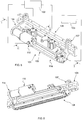
- the screen printing system comprises a screen printing head 101, a control unit 102 which is operative to control the operation of the screen printing head 101, and a print medium supply 103 which is operative to charge the screen printing head 101 with print medium.
- the screen printing head 101 in this embodiment an elongate head, comprises a print head assembly 104 and a support member 105 to which the print head assembly 104 is mounted.
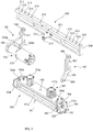
- the print head assembly 104 comprises a print unit 106, in this embodiment an elongate unit, a first support bracket 107 which is attached to the support member 105 and one end of the print unit 106, a second support bracket 109, as a drive bracket, which is attached to the support member 105 and the other end of the print unit 106, and a drive unit 110 for driving a rotatable unit 141 within the print unit 106, as will be described in more detail hereinbelow.
- the print unit 106 comprises a main body 111, in this embodiment an elongate body, which includes a print medium cavity 112, in this embodiment an elongate cavity extending along the length of the main body 111, which contains a print medium, and a delivery aperture 113 at a lower surface of the main body 111, in this embodiment an elongate aperture extending along the length of the main body 111, which is in fluid communication with the print medium cavity 112 and through which print medium is delivered from the print medium cavity 112.
- the main body 111 comprises a main body element 111a and first and second end cap elements 111b, 111c, which are disposed to the opposite ends of the main body element 111a.
- the print medium cavity 112 comprises a first, lower chamber 114 which opens to the delivery aperture 113, and a second, upper chamber 115 which is fluidly connected to the lower chamber 114, such as to allow print medium to be supplied from the upper chamber 115 to the lower chamber 114, as will be described in more detail hereinbelow.
- the lower chamber 114 includes an upper surface 119 of arcuate section, here of part-circular section, to which the upper chamber 115 is fluidly connected.
- the upper chamber 115 is of rectangular section and includes parallel side walls which provide for sealing engagement with a piston member 169 of a piston assembly 167, as will be described in more detail hereinbelow.
- the print unit 106 further comprises first and second inwardly and downwardly directed wiper blades 121, 123 which are disposed in opposed relation along opposite sides of the delivery aperture 113 in the main body 111 and clamped to the main body 111, in this embodiment by respective clamping plates and screws, and sealing members 125, 125 which are disposed to the opposite ends of the main body 111 and sealingly engage the respective ends of the wiper blades 121, 123, such as to prevent the escape of print medium beyond the ends of the wiper blades 121, 123.
- the wiper blades 121, 123 are in use maintained in sealing contact with a printing screen 129, which includes a plurality of printing apertures 131 and is located above a workpiece 133, in this embodiment a printed circuit board, to which deposits of print medium are to be printed.
- the print unit 106 is symmetrically arranged about the longitudinal axis thereof such as to be moveable bidirectionally.
- the main body 111 further includes first and second attachment elements 135, 137 at the opposite ends thereof, in this embodiment cylindrical bush elements, to which the brackets 107, 109 are attached.
- the attachment elements 135, 137 are configured to provide for pivoting of the print unit 106 relative to the brackets 107, 109, such as to enable the wiper blades 121, 123 to be aligned parallel to the surface of the printing screen 129 so as to maintain a sealing engagement therewith.
- the main body 111 further includes a cam recess 139, in this embodiment at an upper surface thereof, for engagement with a cam member 217 on the support member 105, which is operative to provide for alignment of the print unit 106 relative to the brackets 107, 109 and hence the support member 105.
- the print unit 106 further comprises a rotatable unit 141 which is disposed in the lower chamber 114 of the main body 111, such as to extend along the length thereof, and is rotatable to displace the print medium as contained in the lower chamber 114.
- the rotatable unit 141 is supported in bearings 142, 142, here journal bearings, at the respective ends of the main body 111.
- the purpose of the rotatable unit 141, in displacing print medium, is twofold, firstly in applying a horizontal force to the contained print medium which is such as to counteract the horizontal force as applied to the print medium as a consequence of movement of the print unit 106 and thereby optimize the filling of the printing apertures 131 in the printing screen 129, and secondly in stirring the print medium such as to provide the print medium with an even consistency.
- the rotatable unit 141 comprises a hollow body member 143 which includes an inner cavity 145 and a plurality of transfer apertures 147 which fluidly connect the inner cavity 145 to an external surface thereof, such as to allow for the transfer of print medium between the inner cavity 145 and the lower chamber 114 of the main body 111.
- the body member 143 comprises a perforated cylindrical member, here a mesh including an array of transfer apertures 147, and a central body 151 which extends along the length of the body member 143, in this embodiment as a shaft, such that the inner cavity 145 is an annular cavity, here of circular section.
- the transfer apertures 147 can have a regular pattern. In another embodiment the transfer apertures 147 can have an irregular pattern.
- the rotatable unit 141 includes a drive gear arrangement 153, here comprising first and second driven gears 153a, 153b which are coupled to one end of the central body 151, by which the rotatable unit 141 is rotated by the drive unit 110, as will be described in more detail hereinbelow.
- a drive gear arrangement 153 here comprising first and second driven gears 153a, 153b which are coupled to one end of the central body 151, by which the rotatable unit 141 is rotated by the drive unit 110, as will be described in more detail hereinbelow.
- the main body 111 includes a charging port 155 through which the print medium cavity 112 is charged with print medium, and a check valve 157 for selectively opening and closing the charging port 155.
- the check valve 157 comprises a delivery channel 159 and a plug member 161 which is moveable relative to the delivery channel 159 between a first, closed position, in which the delivery channel 159 is closed and a second, open position, in which the delivery channel 159 is open, such as to allow for charging of the print medium cavity 112 in the main body 111 with print medium.
- the plug member 161 includes a pin 163 which constrains the movement of the plug member 161 between the open and closed positions, and also acts to provide an operator with a visible indication as to whether the check valve 157 is open or closed.
- the plug member 161 is pneumatically actuated, such as to be movable between the open and closed positions on the application of a pneumatic supply, typically a compressed air supply.
- the charging port 155 is permanently connected to the print medium supply 103, but in an alternative embodiment the charging port 155 can be connected to the print medium supply 103 only at the time of charging the print unit 106.
- the print unit 106 further comprises a piston assembly 167 which is operative to apply a pressure, in this embodiment a downward pressure, to the print medium as contained in the print medium cavity 112, which downward pressure acts to force print medium to the outlet aperture 113 of the main body 111, in this embodiment as located between the wiper blades 121, 123, and fill the printing apertures 131 in the printing screen 129 as the print unit 106 is moved thereover.
- a pressure in this embodiment a downward pressure
- the piston assembly 167 comprises a piston member 169, in this embodiment an elongate member, which is disposed in the upper chamber 115 in the main body 111 such as to extend along the length thereof and be movable vertically therewithin to pressurize the print medium as contained in the print medium cavity 112, and at least one actuator unit 171 for moving the piston member 169 vertically in the upper chamber 115.
- the piston assembly 167 comprises a plurality of actuator units 171, here first and second actuator units 171a, 171b which are disposed towards the respective ends of the piston member 169.
- actuator units 171a, 171b comprise pneumatic units which are operable by pneumatic pressure to apply a predeterminable pressure to the print medium as contained in the print medium cavity 112.
- the piston member 169 comprises a plurality of seal members 177, which are separated by supporting plates 179, in the manner of a laminated structure.
- the piston member 169 includes at least one print medium indicator 183 for providing a visible indication of the amount of print medium as contained by the print medium cavity 112.
- the piston member 169 includes a plurality of print medium indicators 183a, 183b which extend rearwardly from the piston member 169, such that the extent to which the print medium indicators 183a, 183b extend from the main body 111 indicates the amount of print medium as contained by the print medium cavity 112.
- the brackets 107, 109 each comprise a guide slot 191 which is a sliding fit over the support member 105, an arm member 195 which is attached to a respective end of the print unit 106, and a clamp member 199 which is operative to clamp the brackets 107, 109 to the support member 104 at a desired position.
- the arm member 195 includes a recess 200, here a part-circular recess, at a lower end thereof, which captively engages the attachment member 135, 137 at the respective end of the main body 111 of the print unit 106.
- the recess 200 provides for pivoting of the print unit 106 relative to the brackets 107, 109, such as to allow for alignment of the print unit 106 relative to the support member 105 and hence the printing screen 129 over which the screen printing head 101 is to be traversed.
- the clamp member 199 comprises a clamping screw which engages one of a plurality of clamping apertures 213 in the support member 105 in dependence upon the desired position of the print unit 106 on the support member 105.
- the drive unit 110 comprises a drive motor 203 and a driving gear arrangement 205, here comprising first and second driving gears 205a, 205b, for driving the drive gear arrangement 153 of the rotatable unit 141.
- the drive unit 110 is supported by the drive bracket 109, but could be otherwise supported.
- the support member 105 comprises a main body 209, in this embodiment an elongate body, which includes a fixing 211, in this embodiment comprising a plurality of fixing apertures, for attaching the support member 105 to the carriage of a screen printing machine, a plurality of mounting apertures 213 to respective ones of which the brackets 107, 109 are attached, and a cam member 215 which engages the cam recess 139 in the main body 111 of the print unit 106, such as to allow for alignment of the same relative to the support member 105.
- a fixing 211 in this embodiment comprising a plurality of fixing apertures, for attaching the support member 105 to the carriage of a screen printing machine, a plurality of mounting apertures 213 to respective ones of which the brackets 107, 109 are attached
- a cam member 215 which engages the cam recess 139 in the main body 111 of the print unit 106, such as to allow for alignment of the same relative to the support member 105.
- the mounting apertures 213 are located at predetermined positions, such as to allow for the mounting of print units 106 of different length to the support member 103.
- the cam member 215 includes an eccentric cam 217 which engages the cam recess 139 in the main body 111 of the print unit 106 and, when rotated, causes a small angular rotation of the print unit 106 about the attachment elements 135, 137 thereof, such as to allow for angular alignment of the print unit 106 relative to the support member 105 and hence the printing screen 129 over which the print unit 106 is to be traversed, such as to ensure sealing engagement of the wiper members 121, 123 with the surface of the printing screen 129.
- the control unit 102 is operative to control the actuators 171a, 171b of the piston assembly 167 in applying a predetermined pressure to the print medium as contained in the print medium cavity 112 in the main body 111 of the print unit 106, and the drive motor 203 to drive the rotatable unit 141 within the print unit 106 at a predetermined speed in one of the clockwise or counter-clockwise senses depending upon the direction of movement of the print unit 106.
- the print medium cavity 112 is charged with print medium, in this embodiment by opening the check valve 157 through the displacement of the plug member 161 to the open position, through the application of a pneumatic pressure, and delivering print medium from the print medium supply 103 into the print medium cavity 112.
- the rotatable unit 141 is held stationary during the charging of the print medium cavity 112.
- the rotatable unit 141 can be operated during the charging of the print medium cavity 112, such as to work the print medium and assist in moving the print medium along the print medium cavity 112.
- the check valve 157 is then closed, in this embodiment through the displacement of the plug member 161 to the closed position by the application of a pneumatic pressure.
- the piston assembly 167 is then actuated to apply a predetermined pressure to the print medium as contained in the print medium cavity 112, which pressure, together with a downward force as applied to the screen printing head 101 for providing for sealing engagement of the wiper blades 121, 123 with the printing screen 129, provides for the application of a downward force F1 to the contained print medium, which force F1 acts to fill the printing apertures 131 in the printing screen 129.
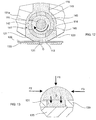
- the print unit 106 is moved laterally over the printing screen 129 in a first, printing direction, in this embodiment in the left to right direction as illustrated, and the rotatable unit 141 is rotated at a predetermined speed in one sense, as illustrated in a clockwise sense.
- the lateral movement of the print unit 106 acts to apply a first horizontal force F2 in a first direction to the print medium as contained in the print medium cavity 112 of the print unit 106. Absent any other applied force, the downward force F1 and the horizontal force F2 would achieve a resultant force which is inclined to the vertical direction as described hereinabove in relation to the prior art screen printing head, thereby reducing the filling efficiency of the printing apertures 131 in the printing screen 129.
- the rotation of the rotatable unit 141 is such as to apply a second horizontal force F3 to the print medium at the delivery aperture 113 of the main body 111 of the print unit 106 in a second direction, which is opposite to the printing direction and the direction of the first horizontal force F2 and counteracts the first horizontal force F2 as generated by lateral movement of the print unit 106.
- the horizontal forces F2, F3 can be matched such as to cancel out one another and thereby provide that the resultant force on the print medium at the delivery aperture 113 of the print unit 106 is only the downward loading force F1.
- This matching of the horizontal forces F2, F3 is achieved by nominally matching the peripheral speed of the rotatable element 141 to the linear speed of movement of the print unit 106.
- the print medium By providing for the application of only the downward loading force F1 to the print medium, the print medium enters the printing apertures 131 in the printing screen 129 vertically downwardly, as illustrated by arrows B in Figure 13 , thereby optimally filling the printing apertures 131 in the printing screen 129, and enabling printing at much faster rates than with existing screen printing heads and also enabling print medium to be pushed uniformly down through holes in a workpiece, such as plated through holes in a printed circuit board as required by a "Pin-in-Paste" process.
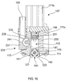
- Figures 14 to 17 illustrate a modified screen printing head 101 for use in the above-described screen printing system.
- This modified screen printing head 101 is quite similar to the above-described screen printing head 101, and thus, in order to avoid unnecessary duplication of description, only the differences will be described in detail, with like reference signs designating like parts.
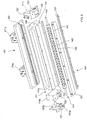
- the screen printing head 101 further comprises a feed mechanism 233 which has the charging port 155 as the inlet thereof to receive print medium from the print medium supply 103 and is operative to charge the upper chamber 115 of the print medium cavity 112 at spaced locations, here at spaced locations along the length of the upper chamber 115.
- a feed mechanism 233 which has the charging port 155 as the inlet thereof to receive print medium from the print medium supply 103 and is operative to charge the upper chamber 115 of the print medium cavity 112 at spaced locations, here at spaced locations along the length of the upper chamber 115.
- the ends of the main body 111 are closed and the check valve 157 is omitted.
- the print medium supply 103 is a conventional print medium cartridge which is pressurised to provide a supply of print medium to the feed mechanism 233.
- the main body 111 of the print unit 106 includes a plurality of transfer ports 235, here six in number, at spaced locations in the lateral wall of the upper chamber 115 of the print medium cavity 112 which are fluidly connected to the feed mechanism 233 and through which print medium is fed by the feed mechanism 233 into the upper chamber 115.
- the feed mechanism 233 comprises an elongate member 237, in this embodiment in the form of a plate, which extends along the length of the lateral wall of the main body 111 adjacent the transfer ports 235 and defines an elongate feed cavity 239 in the main body 111, here a cylindrical channel, which is in fluid communication with each of the transfer ports 235, and a feed element 241, in this embodiment a feed screw, such as an auger screw, which is disposed within the feed cavity 239 and operative, on rotation, to feed print medium through each of the transfer ports 235 in filling the upper chamber 115 of the print medium cavity 112.
- the feed element 241 is supported in bearings 242, 242, here journal bearings, at the respective ends of the main body 111.
- the feed cavity 239 could be formed within an integral main body 111, instead of utilizing a separate elongate member 237.
- the feed mechanism 233 further comprises a drive unit 243 for driving the feed element 241 to charge the upper chamber 115 of the print medium cavity 112.
- the drive unit 243 comprises a drive motor 245 and a gear arrangement 247 which couples the drive motor 245 to the feed element 241.
- the piston member 169 includes a single seal member 251, in the form of lip seal, which is fixed by a supporting plate 253.
Landscapes
- Engineering & Computer Science (AREA)
- Mechanical Engineering (AREA)
- Manufacturing & Machinery (AREA)
- Microelectronics & Electronic Packaging (AREA)
- Physics & Mathematics (AREA)
- General Physics & Mathematics (AREA)
- Screen Printers (AREA)
- Electric Connection Of Electric Components To Printed Circuits (AREA)
- Ink Jet (AREA)
Claims (15)
- Siebdruck-Kopfsystem, welches umfasst:einen Siebdruck-Kopf, der bei einem Druckvorgang in eine erste Richtung über eine Oberfläche eines Werkstücks versetzt wird, um Ablagerungen eines Druckmediums auf dem Werkstück zu drucken, worin der Siebdruck-Kopf umfasst:worin das Siebdruck-Kopfsystem gekennzeichnet ist, dass es weiter umfasst:einen Druckkopf-Aufbau (104) welcher umfasst:eine Druckeinheit (106) mit einem Hauptkörper (111) einschließlich einer Druckmedium-Vertiefung (112), welche bei Verwendung ein Druckmedium enthält, und eine Beschickungs-Öffnung (113), die mit der Druckmedium-Vertiefung (112) in Fluidverbindung steht und durch die Druckmedium bei Verwendung aus der Druckmedium-Vertiefung (112) auf die Oberfläche des Werkstücks geliefert wird;eine drehbare Einheit (141), die in der Druckmedium-Vertiefung (112) des Hauptkörper (111) vorgesehen und drehbar ist, um das Druckmedium, wie in der Druckmedium-Vertiefung (112) enthalten, zu bewegen;
undeine Antriebseinheit (110) zum Drehen der drehbaren Einheit (141);Steuermittel (102) zum Steuern der Antriebseinheit (110) zum Drehen der drehbaren Einheit (141), um das Druckmedium, wie in der Druckmedium-Vertiefung (112) enthalten, zu bewegen, worin das Steuermittel derart ausgestaltet ist, dass die Antriebseinheit (110) betrieben werden kann, um die drehbare Einheit (141) zu drehen, um eine Kraft (F3) auf das Druckmedium an der Beschickungs-Öffnung (113) in dem Hauptkörper (111) in eine zweite Richtung auszuüben, die entgegengesetzt ist zu der ersten Versetzungs-Richtung des Siebdruck-Kopfs, wobei die Kraft (F3), wie in die zweite Richtung ausgeübt, einer Kraft (F2) entgegenwirkt, wie sie durch Versetzung des Siebdruck-Kopfs in die erste Richtung erzeugt wurde. - System nach Anspruch 1, worin die Druckmedium-Vertiefung (112) eine erste Kammer (114) umfasst, die sich an der Beschickungs-Öffnung (113) öffnet und in der die drehbare Einheit (141) angeordnet ist, und eine zweite Kammer (115), die mit der ersten Kammer (114) fluid verbunden ist, so dass das Druckmedium aus der zweite Kammer (115) in die erste Kammer (114) geliefert werden kann, wahlweise worin die erste Kammer (114) eine obere Oberfläche (119) mit einem bogenförmigen Abschnitt beinhaltet, wahlweise worin der bogenförmige Abschnitt ein teilweise ringförmiger Abschnitt ist, wahlweise worin die zweite Kammer (115) mit der oberen Oberfläche (119) der ersten Kammer (114) fluid verbunden ist.
- System nach Anspruch 1 oder 2, worin die drehbare Einheit (141) ein hohles Körperelement (143) umfasst, das eine innere Vertiefung (145) und mehrere Übertragungsöffnungen (147) beinhaltet, die die innere Vertiefung (145) mit der Druckmedium-Vertiefung (112) fluid verbinden, wahlweise worin das Körperelement (143) ein perforiertes zylindrisches Element umfasst, wahlweise worin das zylindrische Element ein Sieb umfasst, welches eine Anordnung von Übertragungsöffnungen (147) über dessen Oberfläche beinhaltet, wahlweise worin das Körperelement (143) einen zentralen Körper (151) beinhaltet, der sich in dem zylindrischen Element intern erstreckt, so dass die innere Vertiefung (145) eine ringförmige Vertiefung ist, wahlweise worin die ringförmige Vertiefung (145) im Wesentlichen ein kreisförmiger Abschnitt ist.
- System nach einem der Ansprüche 1 bis 3, worin die Druckeinheit (106) weiter eine Einheit zum Ausüben von Druck umfasst, die betreibbar ist, auf das Druckmedium, wie in der Druckmedium-Vertiefung (112) enthalten, Druck auszuüben, wahlweise worin die Einheit zum Ausüben von Druck betreibbar ist, um auf das Druckmedium in der Richtung der Beschickungs-Öffnung (113) in dem Hauptkörper (111) Druck auszuüben, wahlweise worin die Einheit zum Ausüben von Druck einen Kolben-Aufbau (167) umfasst, wahlweise worin der Kolbenaufbau (167) ein Kolbenelement (169) umfasst, das in der Druckmedium-Vertiefung (112) bewegbar angeordnet ist, wahlweise worin die Druckmedium-Vertiefung (112) eine erste Kammer (114) umfasst, die sich in die Beschickungs-Öffnung (113) öffnet und in der die drehbare Einheit (141) angeordnet ist, und eine zweite Kammer (115), die mit der ersten Kammer (114) fluid verbunden ist, so dass das Druckmedium aus der zweiten Kammer (115) in die erste Kammer (114) geliefert werden kann, wahlweise worin das Kolbenelement (169) in der zweiten Kammer (115) der Druckmedium-Vertiefung (112) bewegbar angeordnet ist.
- System nach einem der Ansprüche 1 bis 4, worin die drehbare Einheit (141) in einer derartigen Geschwindigkeit gedreht wird, dass die Kraft (F3), wie auf das Druckmedium an der Beschickungs-Öffnung (113) in dem Hauptkörper (111) in die zweite Richtung ausgeübt, im Wesentlichen gleich der Kraft (F2) ist, wie auf das Druckmedium durch Versetzung des Siebdruck-Kopfs in die erste Richtung ausgeübt.
- System nach einem der Ansprüche 1 bis 5, worin der Druckkopf-Aufbau (104) mindestens eine Trägerklammer (107, 109) aufweist, die an der Druckeinheit (106) angebracht ist und über die der Druckkopf-Aufbau (104) an eine Siebdruckvorrichtung befestigt ist, wahlweise worin die Druckeinheit (106) mit der mindestens einen Trägerklammer (107, 109) schwenkbar gekoppelt ist, so dass eine Ausrichtung der Druckeinheit (106) ermöglicht wird, wahlweise worin der Druckkopf-Aufbau (104) erste und zweite Trägerklammern (107, 109) umfasst, die an den jeweiligen Enden der Druckeinheit (106) angebracht sind.
- System nach einem der Ansprüche 1 bis 6, weiter umfassend:einen Befestigungsrahmen (105), an den der Druckkopf-Aufbau (104) befestigt ist, wahlweise worin der Befestigungsrahmen (105) eine Festsetzung (211) beinhaltet, um den Befestigungsrahmen (105) an einen Wagen der Siebdruckvorrichtung anzubringen, wahlweise worin der Befestigungsrahmen (105) ein Ausrichtungselement beinhaltet, das betreibbar ist, in der Druckeinheit (106) einzugreifen, um deren Ausrichtung relativ zu dem Befestigungsrahmen (105) bereit zu stellen, wahlweise worin das Ausrichtungs-Element ein Nocken-Element (215) umfasst.
- System nach einem der Ansprüche 1 bis 7, weiter umfassend:einen Beschickungsmechanismus (233), der betreibbar ist, die Druckmedium-Vertiefung (112) an beabstandeten Stellen zu befüllen, wahlweise worin die Druckmedium-Vertiefung (112) eine längliche Vertiefung umfasst und worin der Beschickungsmechanismus (233) betreibbar ist, die Druckmedium-Vertiefung (112) an beabstandeten Stellen entlang ihrer Länge zu befüllen, wahlweise worin der Hauptkörper (111) mehrere Übertragungsöffnungen (235) beinhaltet, welche sich an beabstandeten Orten in der Druckmedium-Vertiefung (112) öffnen und mit dem Beschickungsmechanismus (233) fluid verbunden sind, wahlweise worin der Hauptkörper (111) eine längliche Beschickungsvertiefung (239) beinhaltet, die mit den Übertragungsöffnungen (235) in Fluidverbindung steht und worin der Beschickungsmechanismus (233) ein Beschickungselement (241) umfasst, das in der Beschickungsvertiefung (239) angeordnet und betriebsbereit ist, das Druckmedium durch die Übertragungsöffnungen (235) zum Füllen der Druckmedium-Vertiefung (112) zu überführen, wahlweise worin die Beschickungsvertiefung (239) teilweise durch ein trennbares längliches Element (237) definiert ist, wahlweise worin die Beschickungsvertiefung (239) einen im Wesentlichen zylindrischen Kanal umfasst, wahlweise worin das Beschickungselement (241) eine Schneckenschraube umfasst, die betreibbar ist, das Druckmedium durch die Übertragungsöffnungen (235) bei Rotation derselben zu überführen, wahlweise worin der Beschickungsmechanismus (233) weiter eine Beschickungs-Antriebseinheit (243) zum Antreiben des Beschickungselements (241) umfasst, um die Druckmedium-Vertiefung (112) mit Druckmedium zu befüllen.
- Verfahren zum Drucken von Ablagerungen eines Druckmediums auf ein Werkstück unter Verwendung eines Siebdruck-Kopfes, worin das Verfahren die Schritte umfasst:Bereitstellen eines Siebdruck-Kopfes, welcher einen Druckkopf-Aufbau (104) aufweist, worin der Druckkopf-Aufbau (104) umfasst: eine Druckeinheit (106), die einen Hauptkörper (111) einschließlich einer Druckmedium-Vertiefung (112) und einer Beschickungs-Öffnung (113) umfasst, welche mit der Druckmedium-Vertiefung (112) in Fluidverbindung steht; eine drehbare Einheit (141), die in der Druckmedium-Vertiefung (112) des Hauptkörpers (111) angeordnet und drehbar ist, das Druckmedium, wie in der Druckmedium-Vertiefung (112) enthalten, zu bewegen; und eine Antriebseinheit (110) zum Drehen der drehbaren Einheit (141);dadurch gekennzeichnet, dass das Verfahren weiter umfasst:Bereitstellen von Steuermittel zum Steuern der Antriebseinheit (110) zum Drehen der drehbaren Einheit (141);Versetzen des Siebdruck-Kopfs in eine erste Richtung über ein Werkstück in einem Druckvorgang; undDrehen der drehbaren Einheit (141), um das Druckmedium, wie in der Druckmedium-Vertiefung (112) enthalten, während der Versetzung des Siebdruck-Kopfs in die erste Richtung über das Werkstück beim Druckvorgang, zu bewegen, um auf das Druckmedium an der Beschickungs-Öffnung (113) in dem Hauptkörper (111) eine Kraft (F3) in eine zweite Richtung auszuüben, die entgegengesetzt ist zu der ersten Richtung der Versetzung des Siebdruck-Kopfs, wobei die in die zweite Richtung ausgeübte Kraft (F3) der durch die Versetzung des Siebdruck-Kopf in die erste Richtung erzeugten Kraft (F2) entgegenwirkt.
- Verfahren nach Anspruch 9, worin die Druckmedium-Vertiefung (112) eine erste Kammer (114) umfasst, die sich an der Beschickungs-Öffnung (113) öffnet und in der die drehbare Einheit (141) angeordnet ist, und eine zweite Kammer (115), die mit der ersten Kammer (114) fluid verbunden ist, so dass das Druckmedium aus der zweite Kammer (115) in die erste Kammer (114) überführt werden kann, wahlweise worin die erste Kammer (114) eine obere Oberfläche (119) mit einem bogenförmigen Bereich umfasst, wahlweise worin der bogenförmige Bereich teilweise ringförmig ist, wahlweise worin die zweite Kammer (115) mit der oberen Oberfläche (119) der ersten Kammer (114) fluid verbunden ist.
- Verfahren nach Anspruch 9 oder 10, worin die drehbare Einheit (141) ein hohles Körperelement (143) umfasst, das eine innere Vertiefung (145) und mehrere Übertragungsöffnungen (147) beinhaltet, die die innere Vertiefung (145) mit der Druckmedium-Vertiefung (112) fluid verbinden, wahlweise worin das Körperelement (143) ein perforiertes zylindrisches Element umfasst, wahlweise worin das zylindrische Element ein Gitter umfasst, das eine Anordnung von Übertragungsöffnungen (147) über dessen Oberfläche aufweist, wahlweise worin das Körperelement (143) einen zentralen Körper (151) beinhaltet, der sich in dem zylindrischen Element intern erstreckt, so dass die innere Vertiefung (145) eine ringförmige Vertiefung ist, wahlweise worin die ringförmige Vertiefung (145) im Wesentlichen ein ringförmiger Abschnitt ist.
- Verfahren nach einem der Ansprüche 9 bis 11, welches weiter den Schritt umfasst: Beschicken der Druckmedium-Vertiefung (112) mit Druckmedium, wahlweise worin die drehbare Einheit (141) während des Schrittes des Beladens der Druckmedium-Vertiefung (112) stationär ist oder sich während des Schritts der Beschickung der Druckmedium-Vertiefung (112) dreht.
- Verfahren nach einem der Ansprüche 9 bis 12, welches weiter den Schritt umfasst: Ausüben von Druck auf das Druckmedium, wie in der Druckmedium-Vertiefung (112) enthalten, wahlweise worin der auf das Druckmedium ausgeübte Druck in Richtung der Beschickungs-Öffnung (113) in dem Hauptkörper (111) ist, wahlweise worin das Ausüben des Drucks den Schritt umfasst:Bewegen eines Kolbenelements (169) in der Druckmedium-Vertiefung (112), um einen Druck auf das Druckmedium in der Druckmedium-Vertiefung (112) auszuüben, wahlweise worin die Druckmedium-Vertiefung (112) eine erste Kammer (114) umfasst, die sich an der Beschickungs-Öffnung (113) öffnet und in der die drehbare Einheit (141) angeordnet ist, und eine zweite Kammer (115), die mit der ersten Kammer (114) fluid verbunden ist, so dass das Druckmedium aus der zweiten Kammer (115) in die erste Kammer (114) überführt werden kann, wahlweise worin das Kolbenelement (169) in der zweiten Kammer (115) der Druckmedium-Vertiefung (112) angeordnet ist.
- Verfahren nach einem der Ansprüche 9 bis 13, worin die drehbare Einheit (141) in einer Geschwindigkeit gedreht wird, dass die Kraft (F3), wie auf das Druckmedium an der Beschickungs-Öffnung (113) in dem Hauptkörper (111) in die zweite Richtung ausgeübt, im Wesentlichen gleich der Kraft (F2) ist, wie auf das Druckmedium durch Versetzen des Siebdruck-Kopfs in die erste Richtung ausgeübt.
- Verfahren nach einem der Ansprüche 9 bis 14, worin der Druckkopf-Aufbau (104) weiter einen Beschickungsmechanismus (233) umfasst, der betreibbar ist, die Druckmedium-Vertiefung (112) mit Druckmedium an beabstandeten Stellen zu beschicken, und weiter den Schritt umfasst:Betreiben des Beschickungsmechanismus (233), um die Druckmedium-Vertiefung (112) mit Druckmedium an beabstandeten Stellen zu beschicken, wahlweise worin die Druckmedium-Vertiefung (112) eine längliche Vertiefung umfasst und worin der Beschickungsmechanismus (233) betreibbar ist, die Druckmedium-Vertiefung (112) an beabstandeten Stellen davon entlang deren Länge zu beschicken, wahlweise worin der Hauptkörper (111) mehrere Übertragungsöffnungen (235) umfasst, die sich an beabstandeten Stellen in der Druckmedium-Vertiefung (112) öffnen und die mit dem Beschickungsmechanismus (233) fluid verbunden sind, wahlweise worin der Hauptkörper (111) eine längliche Beschickungsvertiefung (239) beinhaltet, die mit den Übertragungsöffnungen (235) in Fluidverbindung stehen und worin der Beschickungsmechanismus (233) ein Beschickungselement (241) umfasst, das in der Beschickungsvertiefung (239) angeordnet und betreibbar ist, das Druckmedium durch die Übertragungsöffnungen (235) zum Füllen der Druckmedium-Vertiefung (112) zu liefern, wahlweise worin die Beschickungsvertiefung (239) teilweise durch ein trennbares längliches Element (237) definiert ist, wahlweise worin die Beschickungsvertiefung (239) einen im Wesentlicher zylindrischen Kanal umfasst, wahlweise worin das Beschickungselement (241) eine Schneckenschraube umfasst und worin der Schritt des Betreibens des Beschickungsmechanismus den Schritt umfasst:Drehen der Schneckenschraube, um das Druckmedium durch die Übertragungsöffnungen (235) zu liefern.
Applications Claiming Priority (2)
| Application Number | Priority Date | Filing Date | Title |
|---|---|---|---|
| GB0607118.7A GB2437070B (en) | 2006-04-10 | 2006-04-10 | Screen printing head and system |
| PCT/GB2007/001299 WO2007128981A1 (en) | 2006-04-10 | 2007-04-05 | Screen printing head, system and method |
Publications (2)
| Publication Number | Publication Date |
|---|---|
| EP2010352A1 EP2010352A1 (de) | 2009-01-07 |
| EP2010352B1 true EP2010352B1 (de) | 2017-11-22 |
Family
ID=36539609
Family Applications (1)
| Application Number | Title | Priority Date | Filing Date |
|---|---|---|---|
| EP07732343.4A Active EP2010352B1 (de) | 2006-04-10 | 2007-04-05 | Siebdruckkopfssystem und Verfahren zum Drucken mittels eines Siebdruckkopfes |
Country Status (6)
| Country | Link |
|---|---|
| US (1) | US8371217B2 (de) |
| EP (1) | EP2010352B1 (de) |
| JP (1) | JP5026507B2 (de) |
| CN (1) | CN101500739B (de) |
| GB (1) | GB2437070B (de) |
| WO (1) | WO2007128981A1 (de) |
Families Citing this family (8)
| Publication number | Priority date | Publication date | Assignee | Title |
|---|---|---|---|---|
| KR20130022184A (ko) * | 2011-08-25 | 2013-03-06 | 삼성전자주식회사 | 스퀴즈장치 |
| KR101360022B1 (ko) * | 2011-11-14 | 2014-02-12 | 주식회사 두원정밀 | 스크린 프린터의 솔더 크림 공급장치 |
| TWI545022B (zh) * | 2012-03-22 | 2016-08-11 | 鴻海精密工業股份有限公司 | 絲印機 |
| CN109484011B (zh) * | 2018-09-05 | 2020-10-09 | 浙江金诺纺织科技有限公司 | 一种纺织面料高质量连续式印花装置及其工艺 |
| EP3988312A1 (de) * | 2020-10-23 | 2022-04-27 | Nederlandse Organisatie voor toegepast- natuurwetenschappelijk Onderzoek TNO | Vorrichtung und verfahren zum füllen von nuten |
| CN113619267B (zh) * | 2021-08-20 | 2022-07-26 | 杭州英帕尔标识工程有限公司 | 一种丝网印刷机及应用该丝网印刷机的标识牌制造工艺 |
| CN115742589B (zh) * | 2022-09-15 | 2024-10-29 | 广东众盈传媒科技有限公司 | 一种高均匀性丝网印刷工艺 |
| CN117839968A (zh) * | 2024-01-18 | 2024-04-09 | 浙江合量科技有限公司 | 一种光伏组件封装涂胶装置 |
Family Cites Families (21)
| Publication number | Priority date | Publication date | Assignee | Title |
|---|---|---|---|---|
| AT360955B (de) | 1977-02-04 | 1981-02-10 | Zimmer Johannes | Rakeleinrichtung fuer zylinderschablonen |
| US4622239A (en) * | 1986-02-18 | 1986-11-11 | At&T Technologies, Inc. | Method and apparatus for dispensing viscous materials |
| JP2922320B2 (ja) * | 1991-03-14 | 1999-07-19 | 富士機械製造株式会社 | スクリーン印刷機およびスクリーン印刷方法 |
| US5144892A (en) * | 1991-05-16 | 1992-09-08 | Rockwell International Corporation | Printing fluid circulator for use in a printing press |
| JP3099447B2 (ja) * | 1991-09-02 | 2000-10-16 | 松下電器産業株式会社 | 塗布装置及び方法並びに印刷装置及び方法 |
| JPH05235388A (ja) | 1992-02-24 | 1993-09-10 | Mitsubishi Electric Corp | 低抵抗線状パターンの形成方法及び形成装置並びに太陽電池 |
| JP3610557B2 (ja) * | 1993-05-19 | 2005-01-12 | 谷電機工業株式会社 | スクリーン印刷装置 |
| TW288254B (de) * | 1993-05-19 | 1996-10-11 | Tani Denki Kogyo Kk | |
| US5925187A (en) * | 1996-02-08 | 1999-07-20 | Speedline Technologies, Inc. | Apparatus for dispensing flowable material |
| FR2754473B1 (fr) * | 1996-10-15 | 1999-02-26 | Novatec | Procede de realisation de depots de produit visqueux et/ou pateux sur un substrat a travers les ouvertures d'un pochoir et dispositif distributeur de produit |
| FR2754474B1 (fr) * | 1996-10-15 | 1999-04-30 | Novatec | Dispositif pour le depot d'un produit visqueux ou pateux sur un substrat a travers les ouvertures d'un pochoir |
| GB2352209A (en) * | 1999-07-19 | 2001-01-24 | Dek Printing Machines Ltd | Improvements relating to screen printing |
| CN1382345A (zh) * | 1999-09-01 | 2002-11-27 | 科普拉交互系统国际股份有限公司 | 用于促销的手持式通信设备 |
| JP3646603B2 (ja) * | 2000-02-17 | 2005-05-11 | 松下電器産業株式会社 | スクリーン印刷装置およびスクリーン印刷方法 |
| JP3824292B2 (ja) * | 2000-02-21 | 2006-09-20 | 千住金属工業株式会社 | 高粘度材料の印刷装置 |
| JP2001347635A (ja) * | 2000-06-07 | 2001-12-18 | Matsushita Electric Ind Co Ltd | スクリーン印刷装置およびスクリーン印刷方法 |
| JP3622709B2 (ja) * | 2001-09-03 | 2005-02-23 | 松下電器産業株式会社 | スクリーン印刷装置 |
| WO2003099566A1 (en) * | 2002-05-29 | 2003-12-04 | Tani Denkikogyo Co.,Ltd. | Screen printing apparatus |
| JP2004086438A (ja) * | 2002-08-26 | 2004-03-18 | Brother Ind Ltd | 成形部品、操作パネル、電子機器および成形部品の製造方法 |
| JP4066752B2 (ja) * | 2002-09-11 | 2008-03-26 | 松下電器産業株式会社 | スクリーン印刷装置 |
| JP3889718B2 (ja) * | 2003-03-04 | 2007-03-07 | Smk株式会社 | 電気接点に用いる金属板及び同金属板の製造方法 |
-
2006
- 2006-04-10 GB GB0607118.7A patent/GB2437070B/en not_active Expired - Fee Related
-
2007
- 2007-04-05 WO PCT/GB2007/001299 patent/WO2007128981A1/en not_active Ceased
- 2007-04-05 US US12/296,768 patent/US8371217B2/en active Active
- 2007-04-05 JP JP2009504806A patent/JP5026507B2/ja not_active Expired - Fee Related
- 2007-04-05 EP EP07732343.4A patent/EP2010352B1/de active Active
- 2007-04-05 CN CN200780021631XA patent/CN101500739B/zh not_active Expired - Fee Related
Also Published As
| Publication number | Publication date |
|---|---|
| JP5026507B2 (ja) | 2012-09-12 |
| US8371217B2 (en) | 2013-02-12 |
| GB0607118D0 (en) | 2006-05-17 |
| JP2009533249A (ja) | 2009-09-17 |
| GB2437070A (en) | 2007-10-17 |
| CN101500739B (zh) | 2012-09-05 |
| CN101500739A (zh) | 2009-08-05 |
| EP2010352A1 (de) | 2009-01-07 |
| WO2007128981A1 (en) | 2007-11-15 |
| US20100139509A1 (en) | 2010-06-10 |
| GB2437070B (en) | 2011-12-14 |
Similar Documents
| Publication | Publication Date | Title |
|---|---|---|
| EP2010352B1 (de) | Siebdruckkopfssystem und Verfahren zum Drucken mittels eines Siebdruckkopfes | |
| EP0810091B1 (de) | Tintenzuführvorrichtung für ein Druckgerät | |
| EP2271495B1 (de) | Druckkopfanordnung, siebdrucksystem und verfahren | |
| EP1805030B1 (de) | Fluidhandhabung in tröpfchenaufzeichnungssystemen | |
| US20040187716A1 (en) | Pressure control system for printing a viscous material | |
| KR100224555B1 (ko) | 인쇄용 스퀴지 장치 | |
| EP0368485A2 (de) | Lithographisches Drucken | |
| US20040244612A1 (en) | Method and apparatus for printing viscous material | |
| US6571701B1 (en) | Stirring mechanism for viscous-material printer and method of printing | |
| GB2327196A (en) | Device for varnishing printed materials in an offset printing unit | |
| HK1124565A (en) | Screen printing head system and method | |
| HK1124565B (en) | Screen printing head system and method | |
| KR200412043Y1 (ko) | 반자동식 스크린 인쇄기 | |
| CN111448074B (zh) | 具有带储存容器的装置的加工机械以及用于运行储存容器的方法 | |
| JP7113164B2 (ja) | 印刷装置 | |
| US11059283B2 (en) | Screen printing device | |
| JP2964246B1 (ja) | キーレス印刷機のインキ貯留装置 | |
| CN210283556U (zh) | 一种胶印输墨系统用气缸驱动式墨斗油墨自动搅拌装置 | |
| EP0112543B1 (de) | Farbauftragswerk, insbesondere für Flexo- und Tiefdruckmaschinen mit geschwindigkeitsvariablem Reibzylinder | |
| US20110209639A1 (en) | Rotary Press | |
| HK1153432B (en) | Print head assembly, screen printing system and method |
Legal Events
| Date | Code | Title | Description |
|---|---|---|---|
| PUAI | Public reference made under article 153(3) epc to a published international application that has entered the european phase |
Free format text: ORIGINAL CODE: 0009012 |
|
| 17P | Request for examination filed |
Effective date: 20081110 |
|
| AK | Designated contracting states |
Kind code of ref document: A1 Designated state(s): AT BE BG CH CY CZ DE DK EE ES FI FR GB GR HU IE IS IT LI LT LU LV MC MT NL PL PT RO SE SI SK TR |
|
| AX | Request for extension of the european patent |
Extension state: AL BA HR MK RS |
|
| REG | Reference to a national code |
Ref country code: HK Ref legal event code: DE Ref document number: 1124565 Country of ref document: HK |
|
| DAX | Request for extension of the european patent (deleted) | ||
| RAP1 | Party data changed (applicant data changed or rights of an application transferred) |
Owner name: DTG INTERNATIONAL GMBH |
|
| 17Q | First examination report despatched |
Effective date: 20150304 |
|
| GRAP | Despatch of communication of intention to grant a patent |
Free format text: ORIGINAL CODE: EPIDOSNIGR1 |
|
| INTG | Intention to grant announced |
Effective date: 20170518 |
|
| GRAS | Grant fee paid |
Free format text: ORIGINAL CODE: EPIDOSNIGR3 |
|
| GRAA | (expected) grant |
Free format text: ORIGINAL CODE: 0009210 |
|
| AK | Designated contracting states |
Kind code of ref document: B1 Designated state(s): AT BE BG CH CY CZ DE DK EE ES FI FR GB GR HU IE IS IT LI LT LU LV MC MT NL PL PT RO SE SI SK TR |
|
| RAP1 | Party data changed (applicant data changed or rights of an application transferred) |
Owner name: ASM ASSEMBLY SYSTEMS SINGAPORE PTE. LTD. |
|
| REG | Reference to a national code |
Ref country code: GB Ref legal event code: FG4D |
|
| REG | Reference to a national code |
Ref country code: CH Ref legal event code: EP |
|
| REG | Reference to a national code |
Ref country code: IE Ref legal event code: FG4D |
|
| REG | Reference to a national code |
Ref country code: AT Ref legal event code: REF Ref document number: 947951 Country of ref document: AT Kind code of ref document: T Effective date: 20171215 |
|
| REG | Reference to a national code |
Ref country code: DE Ref legal event code: R096 Ref document number: 602007053113 Country of ref document: DE |
|
| REG | Reference to a national code |
Ref country code: NL Ref legal event code: FP |
|
| REG | Reference to a national code |
Ref country code: LT Ref legal event code: MG4D |
|
| REG | Reference to a national code |
Ref country code: AT Ref legal event code: MK05 Ref document number: 947951 Country of ref document: AT Kind code of ref document: T Effective date: 20171122 |
|
| REG | Reference to a national code |
Ref country code: FR Ref legal event code: PLFP Year of fee payment: 12 |
|
| PG25 | Lapsed in a contracting state [announced via postgrant information from national office to epo] |
Ref country code: ES Free format text: LAPSE BECAUSE OF FAILURE TO SUBMIT A TRANSLATION OF THE DESCRIPTION OR TO PAY THE FEE WITHIN THE PRESCRIBED TIME-LIMIT Effective date: 20171122 Ref country code: SE Free format text: LAPSE BECAUSE OF FAILURE TO SUBMIT A TRANSLATION OF THE DESCRIPTION OR TO PAY THE FEE WITHIN THE PRESCRIBED TIME-LIMIT Effective date: 20171122 Ref country code: LT Free format text: LAPSE BECAUSE OF FAILURE TO SUBMIT A TRANSLATION OF THE DESCRIPTION OR TO PAY THE FEE WITHIN THE PRESCRIBED TIME-LIMIT Effective date: 20171122 Ref country code: FI Free format text: LAPSE BECAUSE OF FAILURE TO SUBMIT A TRANSLATION OF THE DESCRIPTION OR TO PAY THE FEE WITHIN THE PRESCRIBED TIME-LIMIT Effective date: 20171122 |
|
| PG25 | Lapsed in a contracting state [announced via postgrant information from national office to epo] |
Ref country code: BG Free format text: LAPSE BECAUSE OF FAILURE TO SUBMIT A TRANSLATION OF THE DESCRIPTION OR TO PAY THE FEE WITHIN THE PRESCRIBED TIME-LIMIT Effective date: 20180222 Ref country code: GR Free format text: LAPSE BECAUSE OF FAILURE TO SUBMIT A TRANSLATION OF THE DESCRIPTION OR TO PAY THE FEE WITHIN THE PRESCRIBED TIME-LIMIT Effective date: 20180223 Ref country code: AT Free format text: LAPSE BECAUSE OF FAILURE TO SUBMIT A TRANSLATION OF THE DESCRIPTION OR TO PAY THE FEE WITHIN THE PRESCRIBED TIME-LIMIT Effective date: 20171122 Ref country code: LV Free format text: LAPSE BECAUSE OF FAILURE TO SUBMIT A TRANSLATION OF THE DESCRIPTION OR TO PAY THE FEE WITHIN THE PRESCRIBED TIME-LIMIT Effective date: 20171122 |
|
| PG25 | Lapsed in a contracting state [announced via postgrant information from national office to epo] |
Ref country code: SK Free format text: LAPSE BECAUSE OF FAILURE TO SUBMIT A TRANSLATION OF THE DESCRIPTION OR TO PAY THE FEE WITHIN THE PRESCRIBED TIME-LIMIT Effective date: 20171122 Ref country code: DK Free format text: LAPSE BECAUSE OF FAILURE TO SUBMIT A TRANSLATION OF THE DESCRIPTION OR TO PAY THE FEE WITHIN THE PRESCRIBED TIME-LIMIT Effective date: 20171122 Ref country code: EE Free format text: LAPSE BECAUSE OF FAILURE TO SUBMIT A TRANSLATION OF THE DESCRIPTION OR TO PAY THE FEE WITHIN THE PRESCRIBED TIME-LIMIT Effective date: 20171122 Ref country code: CZ Free format text: LAPSE BECAUSE OF FAILURE TO SUBMIT A TRANSLATION OF THE DESCRIPTION OR TO PAY THE FEE WITHIN THE PRESCRIBED TIME-LIMIT Effective date: 20171122 Ref country code: CY Free format text: LAPSE BECAUSE OF FAILURE TO SUBMIT A TRANSLATION OF THE DESCRIPTION OR TO PAY THE FEE WITHIN THE PRESCRIBED TIME-LIMIT Effective date: 20171122 |
|
| REG | Reference to a national code |
Ref country code: DE Ref legal event code: R097 Ref document number: 602007053113 Country of ref document: DE |
|
| PG25 | Lapsed in a contracting state [announced via postgrant information from national office to epo] |
Ref country code: PL Free format text: LAPSE BECAUSE OF FAILURE TO SUBMIT A TRANSLATION OF THE DESCRIPTION OR TO PAY THE FEE WITHIN THE PRESCRIBED TIME-LIMIT Effective date: 20171122 Ref country code: RO Free format text: LAPSE BECAUSE OF FAILURE TO SUBMIT A TRANSLATION OF THE DESCRIPTION OR TO PAY THE FEE WITHIN THE PRESCRIBED TIME-LIMIT Effective date: 20171122 |
|
| PLBE | No opposition filed within time limit |
Free format text: ORIGINAL CODE: 0009261 |
|
| STAA | Information on the status of an ep patent application or granted ep patent |
Free format text: STATUS: NO OPPOSITION FILED WITHIN TIME LIMIT |
|
| REG | Reference to a national code |
Ref country code: HK Ref legal event code: GR Ref document number: 1124565 Country of ref document: HK |
|
| 26N | No opposition filed |
Effective date: 20180823 |
|
| PG25 | Lapsed in a contracting state [announced via postgrant information from national office to epo] |
Ref country code: SI Free format text: LAPSE BECAUSE OF FAILURE TO SUBMIT A TRANSLATION OF THE DESCRIPTION OR TO PAY THE FEE WITHIN THE PRESCRIBED TIME-LIMIT Effective date: 20171122 Ref country code: MC Free format text: LAPSE BECAUSE OF FAILURE TO SUBMIT A TRANSLATION OF THE DESCRIPTION OR TO PAY THE FEE WITHIN THE PRESCRIBED TIME-LIMIT Effective date: 20171122 |
|
| REG | Reference to a national code |
Ref country code: BE Ref legal event code: MM Effective date: 20180430 |
|
| REG | Reference to a national code |
Ref country code: IE Ref legal event code: MM4A |
|
| PG25 | Lapsed in a contracting state [announced via postgrant information from national office to epo] |
Ref country code: LU Free format text: LAPSE BECAUSE OF NON-PAYMENT OF DUE FEES Effective date: 20180405 |
|
| PG25 | Lapsed in a contracting state [announced via postgrant information from national office to epo] |
Ref country code: BE Free format text: LAPSE BECAUSE OF NON-PAYMENT OF DUE FEES Effective date: 20180430 |
|
| PG25 | Lapsed in a contracting state [announced via postgrant information from national office to epo] |
Ref country code: IE Free format text: LAPSE BECAUSE OF NON-PAYMENT OF DUE FEES Effective date: 20180405 |
|
| PG25 | Lapsed in a contracting state [announced via postgrant information from national office to epo] |
Ref country code: MT Free format text: LAPSE BECAUSE OF NON-PAYMENT OF DUE FEES Effective date: 20180405 |
|
| PG25 | Lapsed in a contracting state [announced via postgrant information from national office to epo] |
Ref country code: TR Free format text: LAPSE BECAUSE OF FAILURE TO SUBMIT A TRANSLATION OF THE DESCRIPTION OR TO PAY THE FEE WITHIN THE PRESCRIBED TIME-LIMIT Effective date: 20171122 |
|
| PG25 | Lapsed in a contracting state [announced via postgrant information from national office to epo] |
Ref country code: PT Free format text: LAPSE BECAUSE OF FAILURE TO SUBMIT A TRANSLATION OF THE DESCRIPTION OR TO PAY THE FEE WITHIN THE PRESCRIBED TIME-LIMIT Effective date: 20171122 Ref country code: HU Free format text: LAPSE BECAUSE OF FAILURE TO SUBMIT A TRANSLATION OF THE DESCRIPTION OR TO PAY THE FEE WITHIN THE PRESCRIBED TIME-LIMIT; INVALID AB INITIO Effective date: 20070405 |
|
| PG25 | Lapsed in a contracting state [announced via postgrant information from national office to epo] |
Ref country code: IS Free format text: LAPSE BECAUSE OF FAILURE TO SUBMIT A TRANSLATION OF THE DESCRIPTION OR TO PAY THE FEE WITHIN THE PRESCRIBED TIME-LIMIT Effective date: 20180322 |
|
| REG | Reference to a national code |
Ref country code: DE Ref legal event code: R081 Ref document number: 602007053113 Country of ref document: DE Owner name: ASMPT SMT SINGAPORE PTE. LTD., SG Free format text: FORMER OWNER: ASM ASSEMBLY SYSTEMS SINGAPORE PTE LTD., SINGAPUR, SG |
|
| REG | Reference to a national code |
Ref country code: NL Ref legal event code: HC Owner name: ASMPT SMT SINGAPORE PTE. LTD.; SG Free format text: DETAILS ASSIGNMENT: CHANGE OF OWNER(S), CHANGE OF OWNER(S) NAME; FORMER OWNER NAME: ASM ASSEMBLY SYSTEMS SINGAPORE PTE. LTD. Effective date: 20230301 |
|
| P01 | Opt-out of the competence of the unified patent court (upc) registered |
Effective date: 20230530 |
|
| PGFP | Annual fee paid to national office [announced via postgrant information from national office to epo] |
Ref country code: NL Payment date: 20240418 Year of fee payment: 18 |
|
| PGFP | Annual fee paid to national office [announced via postgrant information from national office to epo] |
Ref country code: GB Payment date: 20240418 Year of fee payment: 18 |
|
| PGFP | Annual fee paid to national office [announced via postgrant information from national office to epo] |
Ref country code: DE Payment date: 20240418 Year of fee payment: 18 |
|
| PGFP | Annual fee paid to national office [announced via postgrant information from national office to epo] |
Ref country code: CH Payment date: 20240501 Year of fee payment: 18 |
|
| PGFP | Annual fee paid to national office [announced via postgrant information from national office to epo] |
Ref country code: IT Payment date: 20240424 Year of fee payment: 18 Ref country code: FR Payment date: 20240426 Year of fee payment: 18 |
|
| REG | Reference to a national code |
Ref country code: DE Ref legal event code: R119 Ref document number: 602007053113 Country of ref document: DE |
|
| REG | Reference to a national code |
Ref country code: CH Ref legal event code: H13 Free format text: ST27 STATUS EVENT CODE: U-0-0-H10-H13 (AS PROVIDED BY THE NATIONAL OFFICE) Effective date: 20251125 |
|
| REG | Reference to a national code |
Ref country code: NL Ref legal event code: MM Effective date: 20250501 |
|
| GBPC | Gb: european patent ceased through non-payment of renewal fee |
Effective date: 20250405 |
|
| PG25 | Lapsed in a contracting state [announced via postgrant information from national office to epo] |
Ref country code: DE Free format text: LAPSE BECAUSE OF NON-PAYMENT OF DUE FEES Effective date: 20251104 |
|
| PG25 | Lapsed in a contracting state [announced via postgrant information from national office to epo] |
Ref country code: GB Free format text: LAPSE BECAUSE OF NON-PAYMENT OF DUE FEES Effective date: 20250405 |
|
| PG25 | Lapsed in a contracting state [announced via postgrant information from national office to epo] |
Ref country code: FR Free format text: LAPSE BECAUSE OF NON-PAYMENT OF DUE FEES Effective date: 20250430 Ref country code: NL Free format text: LAPSE BECAUSE OF NON-PAYMENT OF DUE FEES Effective date: 20250501 |
|
| PG25 | Lapsed in a contracting state [announced via postgrant information from national office to epo] |
Ref country code: CH Free format text: LAPSE BECAUSE OF NON-PAYMENT OF DUE FEES Effective date: 20250430 |
|
| PG25 | Lapsed in a contracting state [announced via postgrant information from national office to epo] |
Ref country code: IT Free format text: LAPSE BECAUSE OF NON-PAYMENT OF DUE FEES Effective date: 20250405 |