EP2010427B1 - Bicyclette equipe avec un systeme de pedalier-manivelle et propulse par le conducteur par ses pieds en mouvement alternatif vertical reciproque - Google Patents
Bicyclette equipe avec un systeme de pedalier-manivelle et propulse par le conducteur par ses pieds en mouvement alternatif vertical reciproque Download PDFInfo
- Publication number
- EP2010427B1 EP2010427B1 EP07731210A EP07731210A EP2010427B1 EP 2010427 B1 EP2010427 B1 EP 2010427B1 EP 07731210 A EP07731210 A EP 07731210A EP 07731210 A EP07731210 A EP 07731210A EP 2010427 B1 EP2010427 B1 EP 2010427B1
- Authority
- EP
- European Patent Office
- Prior art keywords
- axis
- pedal
- gear
- ring
- crank arms
- Prior art date
- Legal status (The legal status is an assumption and is not a legal conclusion. Google has not performed a legal analysis and makes no representation as to the accuracy of the status listed.)
- Not-in-force
Links
- 230000033001 locomotion Effects 0.000 claims abstract description 12
- 230000005540 biological transmission Effects 0.000 claims description 14
- 230000035939 shock Effects 0.000 claims description 2
- 230000008878 coupling Effects 0.000 claims 5
- 238000010168 coupling process Methods 0.000 claims 5
- 238000005859 coupling reaction Methods 0.000 claims 5
- 230000013011 mating Effects 0.000 claims 2
- 239000006096 absorbing agent Substances 0.000 claims 1
- 230000001131 transforming effect Effects 0.000 claims 1
- 230000002787 reinforcement Effects 0.000 abstract 1
- 238000013016 damping Methods 0.000 description 3
- 230000003247 decreasing effect Effects 0.000 description 2
- 230000003387 muscular Effects 0.000 description 2
- 238000010521 absorption reaction Methods 0.000 description 1
- 230000009194 climbing Effects 0.000 description 1
- 238000000034 method Methods 0.000 description 1
- 230000001141 propulsive effect Effects 0.000 description 1
- 230000003014 reinforcing effect Effects 0.000 description 1
- 230000000630 rising effect Effects 0.000 description 1
Images


Classifications
-
- B—PERFORMING OPERATIONS; TRANSPORTING
- B62—LAND VEHICLES FOR TRAVELLING OTHERWISE THAN ON RAILS
- B62M—RIDER PROPULSION OF WHEELED VEHICLES OR SLEDGES; POWERED PROPULSION OF SLEDGES OR SINGLE-TRACK CYCLES; TRANSMISSIONS SPECIALLY ADAPTED FOR SUCH VEHICLES
- B62M1/00—Rider propulsion of wheeled vehicles
- B62M1/24—Rider propulsion of wheeled vehicles with reciprocating levers, e.g. foot levers
- B62M1/30—Rider propulsion of wheeled vehicles with reciprocating levers, e.g. foot levers characterised by the use of intermediate gears
Definitions
- the present invention relates to a new two-wheel equipped with a pedal system propelled by the feet of the driver which converts reciprocal vertical reciprocating movement in unidirectional rotation.
- WO 0230732 discloses a transmission system for cycles according to the preamble of claim 1.
- driver-driven bicycles are not effective for the general public. Especially because they are not "propulsive" at high speed and uncomfortable during pedaling when climbing on steep slopes.
- This new bicycle makes it possible to produce more performance with the same force invested than in a conventional bicycle.
- This two-wheeled vehicle is equipped with a pedal system that transmits a moment of superior strength thanks to the long length of the crank-rack crank.
- crank-cranks (1D, 1G) can describe a reciprocating vertical reciprocating movement and that a crankset is always accessible at the top for a push of the foot by the driver without having to push back the pedal by the driver by making two muscular efforts controlled
- a differential gears device with several bevel gears or non-conical (15) has been positioned. by.
- the differential gear receivers move the crankset downwards by its own differential gears that have become sensors, and then upside down continuously.
- the driver In the crank-link crank solution where the housing system with the differential clearance is not present, to advance the bicycle, the driver must start the progression by pressing the pedal at the top. (on the fig.8, -9 , -10, -11 this is the left pedal)
- This system comprises an intermediate rod pivoting on an axis (Dx) located on the bottom cranks (18), and a second connecting rod (17) rotating with the rings around on the central axis of the plates (Cx) of rings (5). ).
- the pivoting connecting rod and the crown of the crown plate articulate (18) freely on an axis (Bx) rotatable without propelling back thanks to the unidirectional freewheel system of the cassettes.
- This possible technical transmission solution allows reciprocally push the pedal already low and after a turn of the crown forward, lying at the top without the need to install a differential gears system with several bevel gears or non conical, according to the Fig. 1. and fig. 2 .
- the transmission crowns can be installed in several diameters (5) and with several numbers of teeth to obtain multiple speeds by a derailleur of crowns.
- the connecting rod receiver (19) can be equipped with an adjustable extension device to make it possible to increase or decrease the length of the latter and to replace the different diameters of the crown plates which are used to change gears.
- an adjustable extension device By increasing or decreasing the length of this link, the distances between the axes of rotation change and the moments of force can be different.
- the energy invested in the propulsion also increases thanks to the moment of force.
- the high speed propulsion is possible by translating the cranks less quickly.
- crank-pedal cranks (1D, 1G) The length of the vertical movements of the crank-pedal cranks (1D, 1G) is delimited by the distance between the rotating axes of these two parts of the mechanism (17,19) and also the distance between the central axis (Ex) of the connecting rods. pedal cranks and the central axis of rotation of the crown (Cx).
- the entire monocoque front frame (21,22,23) and the rear frame can be joined at the intermediate axis (Fx). It can rotate horizontally including the damping system assembled with the technical method of assembly, so-called "split heads".
- the pivot head (20) of the main rear frame is cut in such a way that the monocoque frame head is inserted into it.
- the main head is in one piece and the removable head secondary, or the main head is removable in two parts and the secondary head is monobloc.
- the horizontal tube includes two independent transmission hub systems, which are linked to the crown plate for propelling the crowns forward (13 or 13BIS).
- the principle of this mechanism applies in two directions: when one of the two racks rises thanks to the differential clearance of the pinions (15) integrated in the central rotating-pivoting axis of the pedals (Ex), the other pedal is loaded by the force of the user of the bicycle, and propelled forward the trays of the crowns.
- the rising rack rotates the unidirectional transmission - freewheel (13 or 13BIS), and therefore does not participate in the propulsion by turning in the other direction.
- the unidirectional freewheel system acts in the same way when the corresponding rack rotates it backwards.
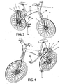
- the right pedal On the fig.1, fig.2 , fig.3, fig.4 , the right pedal is in high position. Down the pedals of the right rack propels the sprocket of the crown plate with the entire chain and the transmission hub of the rear wheel. At the same time the left crankset rises and turns in reverse the unidirectional freewheel system.
- an anti-rotation brake device has been integrated into the gear differential set (15).
- the braking is done from a certain limit of inclination of the pedal with teeth specially placed on the gables.
- crank-pedal can be made with a crank-rod system as such: the crown rods (19) fixed with the crown plate (5) , and propelled around the axis Bx (articulated connection) (18) by the intermediate rod (17) which pivots on the axis of the hinge housing (16).
- crank-crank pedal solution is not equipped with unidirectional transmissions - freewheel at the crown plate.
- the latter can rotate freely about its axis forward and backward.
- the only unidirectional transmission - freewheel is integrated in the set of cassettes (8) allowing the propulsion only forward.
- the entire rear frame carrying the propulsion systems pivots around the axis Fx using a damping system integrated into the frame head (20) or an external damping system fixed on the part of the frame.
- the front frame is assembled including the monocoque (21) and the rotary axis Gx or the front fork (22) with the shock absorption and the front wheel (24), rotate by defining the direction of the bicycle forwarding .
Landscapes
- Engineering & Computer Science (AREA)
- Chemical & Material Sciences (AREA)
- Combustion & Propulsion (AREA)
- Transportation (AREA)
- Mechanical Engineering (AREA)
- Transmission Devices (AREA)
- Automatic Cycles, And Cycles In General (AREA)
- Steering Devices For Bicycles And Motorcycles (AREA)
- Axle Suspensions And Sidecars For Cycles (AREA)
- Automatic Assembly (AREA)
- Motorcycle And Bicycle Frame (AREA)
Description
- La présente invention concerne un nouveau deux roues équipé avec une système de pédalier propulsé par les pieds du conducteur qui transforme le mouvement de translation alternatif vertical réciproque èn un mouvement de rotation unidirectionnelle.
- Le document
WO 0230732 - Les véhicules à deux roues classiques dits bicyclettes propulsés par le conducteur ne sont pas efficaces pour le grand public. Notamment parce qu'ils ne sont pas "propulsibles" à haute vitesse et inconfortables pendant le pédalage lors de l'ascension sur des pentes fortes.
- Cette nouvelle bicyclette permet de produire plus de performance avec la même force investie que dans une bicyclette classique.
- Ce véhicule à deux roues est équipé d'un système de pédalier qui permet de transmettre un moment de force supérieure grâce à la longueur élevée de la manivelle-crémaillère du pédalier.
- La transmission des forces générées par les pieds du conducteur en poussant verticalement l'un des pédaliers de la bicyclette (
fig. 1,-2 ,-3,-4,-5,-6) vers le bas, est résolue avec une crémaillère (3) fixée sur ces manivelles-pédaliers (1D-pour le pédalier Droit, 1G-pour le pédalier Gauche) et actionne le pignon de la couronne (4) fixée sur l'axe tournant de la couronne (5), en faisant avancer la roue arrière (25) par une liaison de la chaîne (6) moyennant les cassettes de pignon(s) (8) de la roue arrière. - Afin d'assurer que les pédaliers-manivelles (1D, 1G) puissent décrire un mouvement alternatif de va-et-vient vertical réciproque et qu'un pédalier soit toujours accessible en haut pour un poussement de pied par le conducteur sans être obligé de repousser le pédalier par le conducteur en faisant deux efforts musculaire contrôlés, un dispositif de boite de jeux différentiel à plusieurs pignons coniques ou non-coniques (15) a été positionnées. par. ex.: quand le pédalier gauche monte obligeant à tourner vers l'arrière son pignon différentiel, les récepteurs pignons différentiels font descendre le pédalier droit par ses propres pignons différentiels devenus capteurs, et puis à l'envers en continu. Dans la solution pédalier manivelle-bielle où le système de boîtier avec le jeu différentiel n'est pas présent, pour faire avancer le bicyclette, le conducteur doit démarrer la progression en appuyant sur le pédalier se trouvant plus en haut. (sur la
fig.8,-9 ,-10,-11 c'est le pédalier gauche) - Plus les manivelles-pédaliers (1D, 1G) ont une longueur élevée, plus le développement permet d'être adapté à une progression dans les pentes fortes.
- Selon des modes particuliers de réalisation de ce véhicule à deux roues propulsé par le conducteur :
- la crémaillère (3) peut être remplacée par un système de bielle-manivelle (
fig. 8,-9 ,-10,-11) pour transformer le mouvement de translation en va-vient vertical en un mouvement de rotation. - Ce système comporte une bielle intermédiaire pivotant sur un axe (Dx) se trouvant sur les manivelles de pédalier (18), et une deuxième bielle (17) tournant avec les couronnes autour sur l'axe central des plateaux (Cx) de couronnes (5). La bielle-intermédiaire pivotante et la bielle du plateau de la couronnes s'articulent (18) librement sur un axe (Bx) pouvant tourner sans faire propulser vers l'arrière grâce au système de roue libre unidirectionnelle des cassettes. Cette éventuelle solution technique de transmission permet de réciproquement repousser le pédalier déjà se trouvant bas et après un tour de la couronne vers l'avant, se trouvant en haut sans avoir besoin d'installer un système de jeu différentiel à plusieurs pignons coniques ou non-coniques, selon les
fig. 1. et fig. 2 . - Pour offrir à l'usager une large marge de choix de vitesse adaptée à un confort maximal pour ce véhicule à crémaillère-manivelles pédalier (
fig. 1.-2 .-3.-4) ou bielle-manivelle pédalier propulsé par le conducteur pendant les efforts musculaires, les couronnes de transmission peuvent être installées en plusieurs diamètres (5) et avec plusieurs nombres de dents afin d'obtenir plusieurs vitesses par un dérailleur de couronnes. - Pour la solution technique de propulsion à bielle-manivelle pédalier, le récepteur bielle (19) peut être équipé par un dispositif de rallonge ajustable pour permettre d'augmenter ou de diminuer la longueur de ce dernier et remplacer les différents diamètres des plateaux de couronnes qui servent à changer les vitesses. En augmentant ou diminuant la longueur de cette bielle, les distance entre les axes de rotation changent et les moments de force peuvent être différents. En augmentant la longueur de la bielle de plateau, l'énergie investie dans la propulsion augmente aussi grâce au moment de force. En diminuant cette distance, la propulsion à haute vitesse est possible en translatant les pédaliers moins rapidement.
- La longueur des mouvements verticaux des bielle-manivelles pédaliers (1D, 1G) est délimitée par la distance entre les axes tournant de ces deux parties du mécanisme (17,19) et aussi la distance entre l'axe central (Ex) des bielles-manivelles pédalier et l'axe de rotation central de la couronne (Cx).
- Le cadre de cette bicyclette est composé de deux parties distinctes:
- La partie avant avec le jeu de direction et la fourche (téléscopique éventuellement),le tout formant un ensemble avec le cadre qui peut être en monocoque (21, 22, 23);
- La deuxième partie comprend la fourche arrière (11), le tube supérieur du cadre arrière (14) qui inclut l'axe horizontal (Cx), le boîtier de jeu différentiel (15) pour assurer le réciprocité des mouvements verticaux des pédaliers, et la fourche de renforcement (12) qui reprend les contraintes élevées provenant du tube supérieur du cadre arrière en répartissant les forces au niveau du centre de fixation de la roue arrière.
- L'ensemble du cadre avant monocoque (21,22,23) et le cadre arrière peuvent être joints au niveau de l'axe intermédiaire (Fx). Celui-ci peut pivoter horizontalement en incluant le système d'amortissement assemblé avec la méthode technique d'assemblage, dits "têtes fendues". La tête (20) de pivot du cadre arrière principal est taillé de manière à ce que la tête du cadre monocoque s'y insère. Pour cela, soit la tête principale est en monobloc et la tête secondaire démontable, soit la tête principale est démontable en deux parties et la tête secondaire est monobloc. Ces solutions permettent l'utilisation d'un assemblage de cadres différents avec une même pièce principale. Par ex.: on peut changer le cadre principal ou le cadre monocoque avant pour obtenir un autre type de bicyclette (multi-assemblage).
- Le tube horizontal inclut deux systèmes indépendants de moyeux de transmission, qui sont liés au plateau de couronnes permettant de propulser les couronnes vers l'avant.(13 ou 13BIS). Le principe de ce mécanisme s'applique dans deux directions : quand l'une des deux crémaillères monte grâce au jeu différentiel des pignons (15) intégrés dans l'axe central rotatif-pivotant des pédaliers (Ex), l'autre pédalier est chargé par la force de l'utilisateur de la bicyclette, et propulsé vers l'avant les plateaux des couronnes. La crémaillère montante fait tourner à l'inverse le jeu de transmission unidirectionnelle - roue libre (13 ou 13BIS), et ne participe donc pas à la propulsion en tournant dans l'autre sens. Côté plateau de couronnes le système de roue libre - unidirectionnelle agit de la même façon quand la crémaillère correspondant le fait tourner vers l'arrière. Sur les
fig.1, fig.2 ,fig.3, fig.4 , le pédalier droit est en position haute. En descendant le pédalier de la crémaillère droite propulse le pignon du plateau de couronnes avec l'ensemble de la chaîne et le moyeu de transmission de la roue arrière. Dans le même temps le pédalier gauche remonte et fait tourner à l'inverse le système de roue libre unidirectionnelle. - Pour empêcher les pédaliers crémaillères de se désolidariser du pignon (4) de la couronnes,et afin de délimiter la trajectoire des manivelles de pédalier, un dispositif de frein antirotation a été intégré dans le jeu de différentiel des pignons (15). Le freinage se fait à partir d'une certaine limite de inclinaison du pédalier avec des dents spécialement placées sur les pignons.
- Pour un mode particulier afin d'éviter le système de jeu différentiel des pignons, la manivelle-pédalier peut être réalisée avec un système bielle-manivelle comme tel: les bielles de la couronne (19) fixées avec le plateau de la couronne (5), et propulsées autour de l'axe Bx (liaison articulée) (18) par la bielle intermédiaire (17) qui pivote sur l'axe du boîtier d'articulation (16).
- La solution du pédalier bielle-manivelle n'est pas équipée de transmissions unidirectionnelles - roue libre au niveau du plateau de couronnes. Ce dernier peut tourner librement autour de son axe vers l'avant et l'arrière. La seule transmission unidirectionnelle - roue libre est intégrée dans les jeu de cassettes (8) permettant la propulsion uniquement vers l'avant.
- L'ensemble du cadre arrière portant les systèmes de propulsion, pivote autour de l'axe Fx utilisant un système d'amortissement intégrés dans la tête de cadre (20) ou un système d'amortissement extérieur fixé sur la partie du cadre. Le cadre avant est assemblé en incluant le monocoque (21) et l'axe rotatif Gx ou la fourche avant (22) avec l'amortissement de choc et la roue avant (24), tournent en définissant la direction de l'avancement de bicyclette.
Claims (5)
- Système de transmission pour cycles comportant :- un cadre avant (21) comprenant une tête de cadre (20) ;- une fourche arrière (11) montée sur la tête de cadre (20);- un tube supérieur de cadre arrière (14) fixé sur la tête de cadre (20) et incluant un premier axe (Cx), transversal à l'axe du tube supérieur ;- des bras manivelles de pédaliers (1D;1G) articulés à l'extrémité d'arbres (2) lesquels sont montés sur une extrémité du tube supérieur de cadre arrière (14) ;- une chaîne (6) destinée à transmettre la puissance entre un plateau (5) et des cassettes de pignons (8) montées sur une roue arrière (25) ;- un dispositif d'accouplement (3 , 4, 5, 13, 13BIS, 15, 17, 19) pour transformer un mouvement alternatif des bras manivelles (1D ;1G) en un mouvement de rotation du ou des plateau(x) (5) transmis à la roue arrière (25) par l' intermédiaire de la chaîne (6) et des cassettes de pignons (8)
caractérisé en ce que
un ou plusieurs plateau(x)-couronne(s) (5) est (sont) monté(s) en rotation autour de l'axe (Cx) transversal à l'axe du tube supérieur de cadre arrière (14) et en ce que ledit dispositif d'accouplement est disposé entre les bras manivelles (1D, 1G) et l'axe (Cx) transversal à l'axe du tube supérieur de cadre arrière - Système de transmission selon la revendication 1, caractérisé en ce que l'accouplement comprend:- deux crémaillères (3) fixées respectivement sur l'un des bras manivelles (1D;1G) et venant en prise avec une couronne respective (13BIS) de pignons (4) liée en rotation autour de l'axe (Cx) transversal à l'axe du tube supérieur de cadre arrière (14) avec un plateau couronne (5) par l'intermédiaire d'un système de roues libres (13) respectif pouvant se placer dans les pignons (4) de la couronne (13BIS) associée ;- un système de différentiel (15) agencé à l'arrière du tube (14) de manière à assurer la réciprocité des mouvements verticaux des bras manivelles (1D ; 1 G).
- Système de transmission pour cycles selon la revendication 1 caractérisé en ce que l'accouplement est formé de :- deux premières bielles (17) articulées respectivement sur les bras manivelles (1D ;1G) autour d'un deuxième axe (Dx) au moyen d'un boitier d'articulation (16),- deux secondes bielles (19), articulées à une extrémité par rapport aux premières bielles (17) autour d'un troisième axe (Bx) et dont la seconde extrémité entraine en rotation le ou les plateau(x) couronne (5) autour du premier axe (Cx).
- Système de transmission selon la revendication 1, caractérisé en ce que la tête de cadre (20) loge un dispositif d'amortissement.
- Système de transmission selon la revendication 1, caractérisé en ce que l'accouplement comprend:- deux chaînes (3) fixées respectivement sur l'un des bras manivelles (1D ;1G) et venant en prise avec une couronne respective (13BIS) de pignons (4) liée en rotation autour de l'axe (Cx) transversal à l'axe du tube supérieur de cadre arrière (14) avec un plateau couronne (5) par l'intermédiaire d'un système de roues libres (13) respectif pouvant se placer dans les pignons (4) de la couronne (13BIS) associée ;- un système de différentiel (15) agencé à l'arrière du tube (14) de manière à assurer la réciprocité des mouvements verticaux des bras manivelles (1D ; 1G).
Applications Claiming Priority (2)
| Application Number | Priority Date | Filing Date | Title |
|---|---|---|---|
| FR0602650A FR2898861B1 (fr) | 2006-03-27 | 2006-03-27 | Dispositif d'assemblage d'une bicyclette equipee avec un systeme de pedalier et propulse par le conducteur par ses pieds en mouvement alternatif vertical et reciproque. |
| PCT/FR2007/000529 WO2007110513A1 (fr) | 2006-03-27 | 2007-03-27 | Bicyclette equipe avec un systeme de pedalier-manivelle et propulse par le conducteur par ses pieds en mouvement alternatif vertical reciproque |
Publications (2)
| Publication Number | Publication Date |
|---|---|
| EP2010427A1 EP2010427A1 (fr) | 2009-01-07 |
| EP2010427B1 true EP2010427B1 (fr) | 2009-10-14 |
Family
ID=37771108
Family Applications (1)
| Application Number | Title | Priority Date | Filing Date |
|---|---|---|---|
| EP07731210A Not-in-force EP2010427B1 (fr) | 2006-03-27 | 2007-03-27 | Bicyclette equipe avec un systeme de pedalier-manivelle et propulse par le conducteur par ses pieds en mouvement alternatif vertical reciproque |
Country Status (9)
| Country | Link |
|---|---|
| US (1) | US8025303B2 (fr) |
| EP (1) | EP2010427B1 (fr) |
| JP (1) | JP5225975B2 (fr) |
| CN (1) | CN101410290B (fr) |
| AT (1) | ATE445531T1 (fr) |
| DE (1) | DE602007002804D1 (fr) |
| DK (1) | DK2010427T3 (fr) |
| FR (1) | FR2898861B1 (fr) |
| WO (1) | WO2007110513A1 (fr) |
Families Citing this family (13)
| Publication number | Priority date | Publication date | Assignee | Title |
|---|---|---|---|---|
| US8128111B2 (en) * | 2009-09-04 | 2012-03-06 | Zike, Llc | Scooter and pedal drive assembly |
| US9114848B2 (en) | 2009-09-04 | 2015-08-25 | Zike, Llc | Pedal-drive system for manually propelling multi-wheeled cycles |
| ITGE20090101A1 (it) * | 2009-12-21 | 2011-06-22 | Battista Emilio Di | Velocipede a propulsione umana sul quale il conducente in posizione eretta muove le gambe come se camminasse in salita |
| US9005060B2 (en) | 2010-10-06 | 2015-04-14 | Zike, Llc | Derailleur |
| US9090311B2 (en) | 2010-10-06 | 2015-07-28 | Zike, Llc | Derailleur |
| US8955861B1 (en) * | 2012-07-19 | 2015-02-17 | Randolph Raviraj Rasiah | Fulcrum lever pedal bar bicycle |
| WO2014108579A1 (fr) * | 2013-01-11 | 2014-07-17 | Brizuela Fernández Fernando | Système de traction de pédalier oscillant avec sélection de rendement pour véhicules de locomotion à pédales |
| CA2899856A1 (fr) * | 2013-01-30 | 2014-08-07 | Paul Sprague | Systeme de propulsion pour vehicules a propulsion humaine |
| US9334015B2 (en) | 2013-03-15 | 2016-05-10 | Zike, Llc | Line derailleur |
| US9890654B2 (en) * | 2013-03-15 | 2018-02-13 | Marc Weber | Gas driven motor |
| WO2015111028A1 (fr) | 2014-01-27 | 2015-07-30 | Danieli & C. Officine Meccaniche S.P.A. | Station d'inspection de bandes laminées en bobines |
| WO2017147342A1 (fr) * | 2016-02-23 | 2017-08-31 | Leonard Wallace | Fabrication efficace de bicyclette |
| CN114030554A (zh) * | 2021-11-19 | 2022-02-11 | 门立山 | 一种多链轮大力矩自行车 |
Family Cites Families (23)
| Publication number | Priority date | Publication date | Assignee | Title |
|---|---|---|---|---|
| US416016A (en) * | 1889-11-26 | Bicycle | ||
| US608674A (en) * | 1898-08-09 | Bicycle-gear | ||
| DE54968C (de) * | O. KLEMM und R. BERTHOLD in Mittweida i. Sachsen, Oberer Stein- 1 weg 421 | Antriebvorrichtung für dreirädrige j Fahrräder mittelst Tritthebel, Sperrklinken und Kettenräder-Uebersetzung | ||
| FR415887A (fr) * | 1910-05-12 | 1910-10-06 | Albert Maupetit | Nouveau système de commande par pédales pour bicyclettes, tricycles, etc. |
| US1505271A (en) * | 1923-09-24 | 1924-08-19 | Bartley G Mcnell | Bicycle |
| US2383000A (en) * | 1943-09-29 | 1945-08-21 | John A Mclean | Bicycle |
| JPS5227141A (en) * | 1975-08-26 | 1977-03-01 | Harisu Dainamitsukusu | Vehicle driven along supporting surface |
| US4161328A (en) * | 1977-03-04 | 1979-07-17 | Boris Efros | Bicycle |
| US4561318A (en) * | 1981-10-05 | 1985-12-31 | Schirrmacher Douglas R | Lever power system |
| US4574649A (en) * | 1982-03-10 | 1986-03-11 | B. D. Yim | Propulsion and speed change mechanism for lever propelled bicycles |
| US4564206A (en) * | 1983-10-11 | 1986-01-14 | Lenhardt Larry G | Pedal drive |
| US4561668A (en) * | 1984-04-05 | 1985-12-31 | Klopfenstein King L | Operator powered reciprocating drive system |
| US4666173A (en) * | 1985-01-08 | 1987-05-19 | Graham Garnard E | Foot pedal drive for bicycles |
| US5242182A (en) * | 1991-12-09 | 1993-09-07 | Bezerra Wilson X | Bicycle and the like |
| US5403027A (en) * | 1993-08-27 | 1995-04-04 | Hwang; Chul | Bicycle with folding frame |
| FR2726532A1 (fr) * | 1994-11-04 | 1996-05-10 | Toulet Claude | Dispositif de transformation de deux mouvements pendulaires alternatifs en un mouvement rotatif continu |
| KR20010040375A (ko) * | 1998-01-21 | 2001-05-15 | 이알엘 인벤치오니 에스.알.엘. | 자전거 |
| DE20108375U1 (de) * | 2000-05-31 | 2001-11-29 | Landau, Roman, Dr., 22301 Hamburg | Trethebel-Fahrrad |
| PT102523A (pt) * | 2000-10-13 | 2002-04-29 | Goldbike Ind De Bicicletas Lda | Trotinete movida a pedais horizontais com ou sem mudancas |
| CN2563082Y (zh) * | 2002-08-02 | 2003-07-30 | 苏援农 | 电动自行车车架及电瓶盒 |
| US20070228687A1 (en) * | 2006-03-17 | 2007-10-04 | Rodger Parker | Bicycle propulsion mechanism |
| EP2018314A4 (fr) * | 2006-05-11 | 2010-04-14 | Fallbrook Technologies Inc | Transmission à variation continue |
| US7896377B2 (en) * | 2006-08-29 | 2011-03-01 | Rashad Na'im Searborough | Lever enhanced pedaling system with multi-speed control system |
-
2006
- 2006-03-27 FR FR0602650A patent/FR2898861B1/fr not_active Expired - Fee Related
-
2007
- 2007-03-27 DE DE602007002804T patent/DE602007002804D1/de active Active
- 2007-03-27 CN CN2007800115821A patent/CN101410290B/zh not_active Expired - Fee Related
- 2007-03-27 JP JP2009502146A patent/JP5225975B2/ja not_active Expired - Fee Related
- 2007-03-27 DK DK07731210.6T patent/DK2010427T3/da active
- 2007-03-27 US US12/225,674 patent/US8025303B2/en not_active Expired - Fee Related
- 2007-03-27 AT AT07731210T patent/ATE445531T1/de not_active IP Right Cessation
- 2007-03-27 WO PCT/FR2007/000529 patent/WO2007110513A1/fr not_active Ceased
- 2007-03-27 EP EP07731210A patent/EP2010427B1/fr not_active Not-in-force
Also Published As
| Publication number | Publication date |
|---|---|
| DK2010427T3 (da) | 2010-02-15 |
| FR2898861A1 (fr) | 2007-09-28 |
| EP2010427A1 (fr) | 2009-01-07 |
| US20090224506A1 (en) | 2009-09-10 |
| CN101410290B (zh) | 2011-11-23 |
| CN101410290A (zh) | 2009-04-15 |
| ATE445531T1 (de) | 2009-10-15 |
| DE602007002804D1 (de) | 2009-11-26 |
| US8025303B2 (en) | 2011-09-27 |
| JP2009531220A (ja) | 2009-09-03 |
| FR2898861B1 (fr) | 2008-05-16 |
| JP5225975B2 (ja) | 2013-07-03 |
| WO2007110513A1 (fr) | 2007-10-04 |
Similar Documents
| Publication | Publication Date | Title |
|---|---|---|
| EP2010427B1 (fr) | Bicyclette equipe avec un systeme de pedalier-manivelle et propulse par le conducteur par ses pieds en mouvement alternatif vertical reciproque | |
| EP0568693A1 (fr) | Systeme complet de transmission integrale pour velos avec adaptation aux motos | |
| WO1981002556A1 (fr) | Perfectionnements aux bicyclettes a mouvement de pedalage alternatif | |
| FR2826924A1 (fr) | Systeme de commande, systeme directionnel pour vehicule leger et tricycle equipe d'un tel systeme | |
| EP3826910A1 (fr) | Velo electrique a chaine de transmission electrique parallele a celle de pedalage, comprenant un mat central integrant le moteur, sa batterie et son electronique de commande | |
| CA2439564A1 (fr) | Suspension arriere d'un vehicule avec une roue motrice portee par un bras oscillant | |
| FR2938232A1 (fr) | Systeme de transmission pour cycle a deux roues | |
| EP0000228B1 (fr) | Dispositif de propulsion musculaire notamment pour un véhicule | |
| CA2740246A1 (fr) | Suspension arriere d'un vehicule a deux roues | |
| WO1991012167A1 (fr) | Dispositif de propulsion pour bicyclette a deux roues motrices et bicyclette munie de ce dispositif | |
| WO2007088275A1 (fr) | Moyeu arriere a vitesses integrees et moyeu avant a dynamo integree permettant un montage transversal des roues pour un velo ou velomoteur | |
| FR2590538A1 (fr) | Appareil d'entrainement d'une charge en rotation par pedalage vers l'avant en position horizontale, applicable plus particulierement aux bicyclettes | |
| EP0837812B2 (fr) | Dispositif de compensation d'effort pour une commande a cable d'un derailleur, notamment pour un velo | |
| EP4561893B1 (fr) | Pédalier pour vélocipède | |
| FR2787413A1 (fr) | Dispositif de propulsion de cycle a l'aide des bras du conducteur | |
| WO2010125272A1 (fr) | System de propulsion utilisant le geste du rameur | |
| FR2624087A1 (fr) | Systeme de propulsion d'un vehicule, notamment bicyclette, utilisant l'energie musculaire des bras et des jambes | |
| RU2239578C1 (ru) | Велосипед для езды в положении полулежа | |
| FR2762283A1 (fr) | Bicyclette a deux roues motrices permettant l'utilisation d'un derailleur sur la roue avant | |
| EP4265512A1 (fr) | Dérailleur arrière modulaire et intégré pour bicyclette | |
| FR3154698A1 (fr) | Tendeur de chaine pour vélo, kit et vélo comportant un tel tendeur | |
| FR3111112A1 (fr) | Système de transmission à assistance motorisée pour vélo et vélo équipé dudit système | |
| FR3033310A1 (fr) | Entrainement pour bicyclette | |
| WO2025176962A1 (fr) | Dispositif de transformation d'un mouvement alternatif rectiligne en mouvement rotatif | |
| WO2002022437A1 (fr) | Structure de bicyclette avec pedales reculantes |
Legal Events
| Date | Code | Title | Description |
|---|---|---|---|
| PUAI | Public reference made under article 153(3) epc to a published international application that has entered the european phase |
Free format text: ORIGINAL CODE: 0009012 |
|
| 17P | Request for examination filed |
Effective date: 20081027 |
|
| AK | Designated contracting states |
Kind code of ref document: A1 Designated state(s): AT BE BG CH CY CZ DE DK EE ES FI FR GB GR HU IE IS IT LI LT LU LV MC MT NL PL PT RO SE SI SK TR |
|
| AX | Request for extension of the european patent |
Extension state: AL BA HR MK RS |
|
| RTI1 | Title (correction) |
Free format text: BICYCLE EQUIPPED WITH A PEDAL CRANK AND PROPELLED BY THE RIDER WITH HIS FEET MOVING UP AND DOWN |
|
| GRAP | Despatch of communication of intention to grant a patent |
Free format text: ORIGINAL CODE: EPIDOSNIGR1 |
|
| DAX | Request for extension of the european patent (deleted) | ||
| GRAS | Grant fee paid |
Free format text: ORIGINAL CODE: EPIDOSNIGR3 |
|
| GRAA | (expected) grant |
Free format text: ORIGINAL CODE: 0009210 |
|
| AK | Designated contracting states |
Kind code of ref document: B1 Designated state(s): AT BE BG CH CY CZ DE DK EE ES FI FR GB GR HU IE IS IT LI LT LU LV MC MT NL PL PT RO SE SI SK TR |
|
| REG | Reference to a national code |
Ref country code: GB Ref legal event code: FG4D Free format text: NOT ENGLISH |
|
| REG | Reference to a national code |
Ref country code: CH Ref legal event code: EP |
|
| REG | Reference to a national code |
Ref country code: IE Ref legal event code: FG4D |
|
| REF | Corresponds to: |
Ref document number: 602007002804 Country of ref document: DE Date of ref document: 20091126 Kind code of ref document: P |
|
| REG | Reference to a national code |
Ref country code: CH Ref legal event code: NV Representative=s name: MICHELI & CIE SA |
|
| REG | Reference to a national code |
Ref country code: DK Ref legal event code: T3 |
|
| LTIE | Lt: invalidation of european patent or patent extension |
Effective date: 20091014 |
|
| PG25 | Lapsed in a contracting state [announced via postgrant information from national office to epo] |
Ref country code: LT Free format text: LAPSE BECAUSE OF FAILURE TO SUBMIT A TRANSLATION OF THE DESCRIPTION OR TO PAY THE FEE WITHIN THE PRESCRIBED TIME-LIMIT Effective date: 20091014 Ref country code: PT Free format text: LAPSE BECAUSE OF FAILURE TO SUBMIT A TRANSLATION OF THE DESCRIPTION OR TO PAY THE FEE WITHIN THE PRESCRIBED TIME-LIMIT Effective date: 20100215 Ref country code: IS Free format text: LAPSE BECAUSE OF FAILURE TO SUBMIT A TRANSLATION OF THE DESCRIPTION OR TO PAY THE FEE WITHIN THE PRESCRIBED TIME-LIMIT Effective date: 20100214 Ref country code: ES Free format text: LAPSE BECAUSE OF FAILURE TO SUBMIT A TRANSLATION OF THE DESCRIPTION OR TO PAY THE FEE WITHIN THE PRESCRIBED TIME-LIMIT Effective date: 20100125 Ref country code: FI Free format text: LAPSE BECAUSE OF FAILURE TO SUBMIT A TRANSLATION OF THE DESCRIPTION OR TO PAY THE FEE WITHIN THE PRESCRIBED TIME-LIMIT Effective date: 20091014 Ref country code: SE Free format text: LAPSE BECAUSE OF FAILURE TO SUBMIT A TRANSLATION OF THE DESCRIPTION OR TO PAY THE FEE WITHIN THE PRESCRIBED TIME-LIMIT Effective date: 20091014 |
|
| REG | Reference to a national code |
Ref country code: IE Ref legal event code: FD4D |
|
| PG25 | Lapsed in a contracting state [announced via postgrant information from national office to epo] |
Ref country code: SI Free format text: LAPSE BECAUSE OF FAILURE TO SUBMIT A TRANSLATION OF THE DESCRIPTION OR TO PAY THE FEE WITHIN THE PRESCRIBED TIME-LIMIT Effective date: 20091014 Ref country code: PL Free format text: LAPSE BECAUSE OF FAILURE TO SUBMIT A TRANSLATION OF THE DESCRIPTION OR TO PAY THE FEE WITHIN THE PRESCRIBED TIME-LIMIT Effective date: 20091014 Ref country code: LV Free format text: LAPSE BECAUSE OF FAILURE TO SUBMIT A TRANSLATION OF THE DESCRIPTION OR TO PAY THE FEE WITHIN THE PRESCRIBED TIME-LIMIT Effective date: 20091014 |
|
| PG25 | Lapsed in a contracting state [announced via postgrant information from national office to epo] |
Ref country code: AT Free format text: LAPSE BECAUSE OF FAILURE TO SUBMIT A TRANSLATION OF THE DESCRIPTION OR TO PAY THE FEE WITHIN THE PRESCRIBED TIME-LIMIT Effective date: 20091014 |
|
| PG25 | Lapsed in a contracting state [announced via postgrant information from national office to epo] |
Ref country code: BG Free format text: LAPSE BECAUSE OF FAILURE TO SUBMIT A TRANSLATION OF THE DESCRIPTION OR TO PAY THE FEE WITHIN THE PRESCRIBED TIME-LIMIT Effective date: 20100114 Ref country code: RO Free format text: LAPSE BECAUSE OF FAILURE TO SUBMIT A TRANSLATION OF THE DESCRIPTION OR TO PAY THE FEE WITHIN THE PRESCRIBED TIME-LIMIT Effective date: 20091014 Ref country code: EE Free format text: LAPSE BECAUSE OF FAILURE TO SUBMIT A TRANSLATION OF THE DESCRIPTION OR TO PAY THE FEE WITHIN THE PRESCRIBED TIME-LIMIT Effective date: 20091014 Ref country code: IE Free format text: LAPSE BECAUSE OF FAILURE TO SUBMIT A TRANSLATION OF THE DESCRIPTION OR TO PAY THE FEE WITHIN THE PRESCRIBED TIME-LIMIT Effective date: 20091014 |
|
| PLBE | No opposition filed within time limit |
Free format text: ORIGINAL CODE: 0009261 |
|
| STAA | Information on the status of an ep patent application or granted ep patent |
Free format text: STATUS: NO OPPOSITION FILED WITHIN TIME LIMIT |
|
| PG25 | Lapsed in a contracting state [announced via postgrant information from national office to epo] |
Ref country code: SK Free format text: LAPSE BECAUSE OF FAILURE TO SUBMIT A TRANSLATION OF THE DESCRIPTION OR TO PAY THE FEE WITHIN THE PRESCRIBED TIME-LIMIT Effective date: 20091014 Ref country code: CZ Free format text: LAPSE BECAUSE OF FAILURE TO SUBMIT A TRANSLATION OF THE DESCRIPTION OR TO PAY THE FEE WITHIN THE PRESCRIBED TIME-LIMIT Effective date: 20091014 |
|
| 26N | No opposition filed |
Effective date: 20100715 |
|
| PG25 | Lapsed in a contracting state [announced via postgrant information from national office to epo] |
Ref country code: GR Free format text: LAPSE BECAUSE OF FAILURE TO SUBMIT A TRANSLATION OF THE DESCRIPTION OR TO PAY THE FEE WITHIN THE PRESCRIBED TIME-LIMIT Effective date: 20100115 Ref country code: MC Free format text: LAPSE BECAUSE OF NON-PAYMENT OF DUE FEES Effective date: 20100331 |
|
| REG | Reference to a national code |
Ref country code: FR Ref legal event code: ST Effective date: 20101130 |
|
| PG25 | Lapsed in a contracting state [announced via postgrant information from national office to epo] |
Ref country code: FR Free format text: LAPSE BECAUSE OF NON-PAYMENT OF DUE FEES Effective date: 20100331 |
|
| REG | Reference to a national code |
Ref country code: FR Ref legal event code: RN |
|
| PG25 | Lapsed in a contracting state [announced via postgrant information from national office to epo] |
Ref country code: IT Free format text: LAPSE BECAUSE OF FAILURE TO SUBMIT A TRANSLATION OF THE DESCRIPTION OR TO PAY THE FEE WITHIN THE PRESCRIBED TIME-LIMIT Effective date: 20091014 |
|
| REG | Reference to a national code |
Ref country code: FR Ref legal event code: FC |
|
| PG25 | Lapsed in a contracting state [announced via postgrant information from national office to epo] |
Ref country code: MT Free format text: LAPSE BECAUSE OF FAILURE TO SUBMIT A TRANSLATION OF THE DESCRIPTION OR TO PAY THE FEE WITHIN THE PRESCRIBED TIME-LIMIT Effective date: 20091014 |
|
| PGRI | Patent reinstated in contracting state [announced from national office to epo] |
Ref country code: FR Effective date: 20110516 |
|
| PGFP | Annual fee paid to national office [announced via postgrant information from national office to epo] |
Ref country code: DK Payment date: 20120330 Year of fee payment: 6 Ref country code: CH Payment date: 20120419 Year of fee payment: 6 |
|
| PG25 | Lapsed in a contracting state [announced via postgrant information from national office to epo] |
Ref country code: CY Free format text: LAPSE BECAUSE OF FAILURE TO SUBMIT A TRANSLATION OF THE DESCRIPTION OR TO PAY THE FEE WITHIN THE PRESCRIBED TIME-LIMIT Effective date: 20091014 |
|
| PG25 | Lapsed in a contracting state [announced via postgrant information from national office to epo] |
Ref country code: HU Free format text: LAPSE BECAUSE OF FAILURE TO SUBMIT A TRANSLATION OF THE DESCRIPTION OR TO PAY THE FEE WITHIN THE PRESCRIBED TIME-LIMIT Effective date: 20100415 Ref country code: LU Free format text: LAPSE BECAUSE OF NON-PAYMENT OF DUE FEES Effective date: 20100327 |
|
| PG25 | Lapsed in a contracting state [announced via postgrant information from national office to epo] |
Ref country code: TR Free format text: LAPSE BECAUSE OF FAILURE TO SUBMIT A TRANSLATION OF THE DESCRIPTION OR TO PAY THE FEE WITHIN THE PRESCRIBED TIME-LIMIT Effective date: 20091014 |
|
| PGFP | Annual fee paid to national office [announced via postgrant information from national office to epo] |
Ref country code: GB Payment date: 20130415 Year of fee payment: 7 Ref country code: BE Payment date: 20130430 Year of fee payment: 7 |
|
| REG | Reference to a national code |
Effective date: 20130331 Ref country code: DK Ref legal event code: EBP |
|
| REG | Reference to a national code |
Ref country code: CH Ref legal event code: PL |
|
| PG25 | Lapsed in a contracting state [announced via postgrant information from national office to epo] |
Ref country code: LI Free format text: LAPSE BECAUSE OF NON-PAYMENT OF DUE FEES Effective date: 20130331 Ref country code: CH Free format text: LAPSE BECAUSE OF NON-PAYMENT OF DUE FEES Effective date: 20130331 |
|
| PG25 | Lapsed in a contracting state [announced via postgrant information from national office to epo] |
Ref country code: DK Free format text: LAPSE BECAUSE OF NON-PAYMENT OF DUE FEES Effective date: 20130331 |
|
| PGFP | Annual fee paid to national office [announced via postgrant information from national office to epo] |
Ref country code: NL Payment date: 20140326 Year of fee payment: 8 |
|
| PGFP | Annual fee paid to national office [announced via postgrant information from national office to epo] |
Ref country code: DE Payment date: 20140411 Year of fee payment: 8 |
|
| GBPC | Gb: european patent ceased through non-payment of renewal fee |
Effective date: 20140327 |
|
| PG25 | Lapsed in a contracting state [announced via postgrant information from national office to epo] |
Ref country code: GB Free format text: LAPSE BECAUSE OF NON-PAYMENT OF DUE FEES Effective date: 20140327 |
|
| REG | Reference to a national code |
Ref country code: FR Ref legal event code: PLFP Year of fee payment: 9 |
|
| PGFP | Annual fee paid to national office [announced via postgrant information from national office to epo] |
Ref country code: FR Payment date: 20150326 Year of fee payment: 9 |
|
| REG | Reference to a national code |
Ref country code: DE Ref legal event code: R119 Ref document number: 602007002804 Country of ref document: DE |
|
| REG | Reference to a national code |
Ref country code: NL Ref legal event code: MM Effective date: 20150401 |
|
| PG25 | Lapsed in a contracting state [announced via postgrant information from national office to epo] |
Ref country code: DE Free format text: LAPSE BECAUSE OF NON-PAYMENT OF DUE FEES Effective date: 20151001 |
|
| REG | Reference to a national code |
Ref country code: FR Ref legal event code: ST Effective date: 20161130 |
|
| PG25 | Lapsed in a contracting state [announced via postgrant information from national office to epo] |
Ref country code: FR Free format text: LAPSE BECAUSE OF NON-PAYMENT OF DUE FEES Effective date: 20160331 |
|
| PG25 | Lapsed in a contracting state [announced via postgrant information from national office to epo] |
Ref country code: NL Free format text: LAPSE BECAUSE OF NON-PAYMENT OF DUE FEES Effective date: 20150401 |
|
| PG25 | Lapsed in a contracting state [announced via postgrant information from national office to epo] |
Ref country code: BE Free format text: LAPSE BECAUSE OF NON-PAYMENT OF DUE FEES Effective date: 20140331 |