EP2010734B1 - Isolierende betonform - Google Patents
Isolierende betonform Download PDFInfo
- Publication number
- EP2010734B1 EP2010734B1 EP07873295A EP07873295A EP2010734B1 EP 2010734 B1 EP2010734 B1 EP 2010734B1 EP 07873295 A EP07873295 A EP 07873295A EP 07873295 A EP07873295 A EP 07873295A EP 2010734 B1 EP2010734 B1 EP 2010734B1
- Authority
- EP
- European Patent Office
- Prior art keywords
- engagement element
- tie
- panels
- anchor
- concrete form
- Prior art date
- Legal status (The legal status is an assumption and is not a legal conclusion. Google has not performed a legal analysis and makes no representation as to the accuracy of the status listed.)
- Not-in-force
Links
Images






Classifications
-
- E—FIXED CONSTRUCTIONS
- E04—BUILDING
- E04B—GENERAL BUILDING CONSTRUCTIONS; WALLS, e.g. PARTITIONS; ROOFS; FLOORS; CEILINGS; INSULATION OR OTHER PROTECTION OF BUILDINGS
- E04B2/00—Walls, e.g. partitions, for buildings; Wall construction with regard to insulation; Connections specially adapted to walls
- E04B2/84—Walls made by casting, pouring, or tamping in situ
- E04B2/86—Walls made by casting, pouring, or tamping in situ made in permanent forms
- E04B2/8635—Walls made by casting, pouring, or tamping in situ made in permanent forms with ties attached to the inner faces of the forms
- E04B2/8641—Walls made by casting, pouring, or tamping in situ made in permanent forms with ties attached to the inner faces of the forms using dovetail-type connections
Definitions
- This invention relates to insulating concrete forms.
- ICFs Insulating Concrete Forms
- an ICF is an expanded plastic, usually polystyrene, form comprising two spaced apart panels.
- US-A-2005/0028467 discloses a tie assembly for a wall form system.
- the form system comprises several form units each having a pair of panels positioned in spaced relation to each other.
- a plurality of tie members connects the panels, each tie member comprising a spacer member transposed transversely between the panels and connecting members embodied in the panels.
- US-A-5,809,728 discloses a further self-supporting concrete form module which includes a pair of form members joined together by moulded plastic rib members. Bearing plates and stabilising plates are employed to support forces applied to the form module.
- US-A-2005/0028466 discloses a system for forming an insulated concrete wall comprising first and second wall panels extending parallel to one another and linked by bridging webs hinged to end sections embedded in the wall panels.
- the hinged bridging web enables the panels to be collapsed against one another for transportation.
- the forms are assembled into a hollow vertical wall into which concrete is poured thereby creating a concrete wall.
- US-2001/0027630 discloses a concrete structure formed using an extender that connects to a web member at least partially disposed within a side panel.
- the extender may be used to extend the length of the connector that interconnects opposed side panels using to provide additional surface area to which concrete can bond.
- the ICF Unlike wood or steel forms, the ICF remains In place and becomes a permanent part of the building providing insulation that contributes to energy efficiency, lower noise, and environmentally responsible practices. There are a large number of design considerations for ICFs not the least of which is ease in constructing the hollow vertical wall with minimum labor costs.
- ICF is an ICF
- a countervailing consideration with respect to the size of the form is the shipping costs.
- Concrete walls constructed using ICFs may be anywhere from four inches in thickness to 24 inches in thickness. Typical wall thicknesses are 4, 6, 8 and 10 inches. In a typical ICF, the panel may be on the order of several inches of thickness. The panels are typically rectangular with the longer axis of the form horizontally oriented.
- a form manufactured and sold by American Polysteel, LLC, located in Albuquerque, New Mexico is two feet high and four feet wide. It will therefore be seen that if a form is shipped ready to use, the overall form may be 2 x 4 feet (height and width) and between 10 and 30 inches in thickness depending upon the thickness of the concrete wall to be constructed. Thus, the volume of the form may be on the order of from 8 to 20 cubic feet. Since shipping costs are in part based upon the volume (as opposed to the weight) of the freight, one way of reducing the volume of the form is to ship the form in a "knocked-down" condition and assembling the form on site. An example of a knock-down flat panel form is shown in Fig. 1 .
- Ties When panels are shipped in a knocked-down condition, the panels are assembled by inserting a structural member between the two panels to hold the panels in spaced apart relation during pouring of the concrete. After the concrete has set, the structural member is embedded in the concrete and thus holds the panels in snug relation to the faces of the concrete wall.
- These structural members are referred to in the ICF industry as "ties.” Ties may be of a wide variety of designs and construction including different types of material. The term “tie” is therefore a generic term for an object that provides the function of maintaining the panels in spaced apart relation.
- the tie must be appropriately anchored in the panels so as to maintain the panels In the desired position thereby defining the thickness of the concrete wall.
- the tie assembly defined as the combination of the tie and the anchor members secured to the panels must be capable of withstanding these considerable forces without separating, i.e., rupturing the integrity of the wall. It is also desirable to provide ties that can be used to support horizontal reinforcing bars (rebars) that are embedded in the concrete wall.
- rebars horizontal reinforcing bars
- the ties may be of various material as may be chosen by one having ordinary skill in the art. It is also desirable that the knocked-down type of ICF can be quickly and easily assembled at the job site. Still another consideration is that the ties which engage the anchors in the opposed panels during assembly of the form at the job site is relatively foolproof so as to avoid errors, such as improper tie insertion into the anchors in a manner such that the tie and anchors inadvertently become disengaged while concrete is poured.
- This invention provides an insulating concrete form comprising:
- first engagement elements may be collectively one of male and female engagement elements, and the second engagement elements are the other of male and female engagement elements.
- each tie may include both a male and a female engagement element such that more than one tie can be engaged between said pair of anchors.
- said female engagement element comprises a C-shaped channel and said male engagement element comprises a T-shaped runner slidably insertable into said C-shaped channel.
- end of said C-shaped channel, said T-shaped runner, or both may be shaped to facilitate slidable entry of said T-shaped runner into said C-shaped channel.
- the end of the T-shaped runner may be pointed to facilitate entry into the C-shaped channel.
- said cantilevered locking tab may be shaped to be slidable through a plurality of said staggered openings.
- said male engagement element may comprise a pair of cantilevered locking tabs, one preventing upward movement and the other preventing downward movement after being positioned in respective ones of the staggered openings in said female engagement element.
- each said first engagement element may be approximately equal to the height of said pair of panels.
- each said second engagement elements may be approximately equal to the height of said pair of panels.
- said furring strip is embedded within one of said panels or exposed on its exterior surface.
- the invention also provides a method of constructing an insulated wall comprising:
- the method may further comprise engaging the anchors and ties on site to form an insulated wall form with a hollow space; and filling the hollow space to form a permanent wall including concrete and Insulating panels.
- the method may also comprise:
- Fig. 1 illustrates one embodiment of an ICF in a fully assembled condition except for one tie which is positioned above the form in readiness for assembly into the form.
- the form 10 comprises a first panel 12 and a second panel 14 shown in spaced-apart relationship so as to define an inner space and constructed of lightweight material such as expanded polystyrene.
- Each panel has an upper edge 16 and a lower edge (not shown).
- Each panel also has an end 18 and an opposite end (not shown).
- the ends and/or upper and lower edges of each panel may be provided with a tongue and groove design so that the panels may be interlocked as the hollow wall comprising multiple ICFs is built.
- a tie assembly comprises a pair of anchors 20, 22 fixedly attached to the respective panels as by embedding the anchors in the panel walls during formation of the panels. It will be understood by those having ordinary skill in the art that the anchors may protrude inwardly from the panel inner surface or may be deeply embedded in the panel.
- the tie assembly also includes a tie shown generally at 24. As seen in Fig. 1 , there may be a plurality and preferably at least two tie assemblies that maintain the panels 12, 14 in spaced relation. The number of tie assemblies depends upon the height and width of the panels as well as the thickness of the wall to be poured.
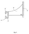
- Anchors 20 and 22 are identical and only one of the anchors will be described in detail with reference to Figs. 2 - 4 .
- the anchor 20 includes two elongated members, a furring strip 25, and an engaging, connecting or holding member or element 26.
- the furring strip 25 and engaging element 26 are connected through one or more webs or stiffener elements 28 or may be integral.
- elongated members 25 and 26 may be connected with a single or several web stiffeners so as to maintain the engaging member 26 in spaced relation to the furring strip 25 while functioning to transfer the load from objects attached to the furring strip (as described below) to the engaging element 26 which attaches to the tie when the insulating concrete form is fully assembled.
- Furring strip 25 comprises an elongated flat plate or strip of material. As seen in Fig. 1 , when the anchor is embedded in the panel 12, the furring strip 25 outer surface is inset from the outer surface of the panel and is covered by the expanded polystyrene panel material. It may be desirable to have the furring strip 25 at the surface of the panel such that after construction of the concrete wall, the position of the furring strips can be easily identified. Alternatively, when the furring strip 25 is embedded in the panel and spaced adjacent to the panel outer surface, the panel may have lines 27 impressed in the panels to show the position of the embedded furring strip.
- the furring strip is made of a material and thickness that can receive fasteners.
- the function of the furring strip is to allow an external covering to be applied to the outer surface of the panel after the wall is fully constructed. For example, it may be desirable to attach, where the concrete wall is an exterior wall of the building, external siding to the completed wall with fasteners attached to the furring strips.
- the exterior surface of the building may be stucco and thus a screen or web material on which the stucco is applied may be attached to the furring strips.
- the surface On the interior side of a concrete wall of a building, the surface may be covered with standard plasterboard that may be secured to the wall with fasteners driven into the furring strips.
- standard plasterboard that may be secured to the wall with fasteners driven into the furring strips.
- the engaging element 26 may have a "C" cross-section so as to form a C-channel elongated engagement element 32 as seen best in Fig. 3 .
- the C-channel 32 has a pair of arms 34 at selected vertical sections of the C-channel.
- the C-channel elongated engaging element 32 has an upper section indicated generally at 36, a lower section indicated generally at 38, and a center section indicated generally at 40.
- the center section 40 comprises a plurality of arm sections 42.
- the C-channel 32 is thus discontinuous along its length such that an arm section 42 on the left side (as viewed in Fig.
- discontinuous C-channel such that the two arms are opposed at the top and bottom sections 36 and 38, but not in the center section 40, where they are unopposed as shown for arm sections 42 and 44 is to permit deflection of the arms as the runner of the tie (to be described) enters and is slidably forced along the length of the C-channel during installation to thereby reduce resistance between the runner and C-channel as the tie is slid into the anchor 20.
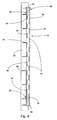
- the upper section 36 of anchor 20 has opposed walls 34 to define a complete "C" section. At the upper end of section 36 the opening between arms 34 is widened as shown at section 46 such that there is provided, as seen in the front view of Fig. 4 , a V-shaped opening 48.
- the lower section 38 also includes a widened portion 46 that also defines a V-shaped opening 48.
- the purpose of the widened portion 46 of the upper and lower sections 36, 38 is to facilitate entry of the tie runner into the C-channel elongated member 32. It is to be noted that the right hand arm 34 in section 36 of the anchor 20 extends lower than the opposed arm 34 by a distance that is approximately equal to the vertical spacing between adjacent arm sections 42.
- the left hand arm extends further upwardly than the right hand arm 34 so as to be complementary to the arrangement of the arms in upper section 36.
- the flared arms 34 at sections 36, 38 increase the width of the opening of the C-channel to more easily receive the tie. Additionally, as seen best in Fig. 2 , the depth of the C-channel is increased at 50 in both the top and bottom sections 36 and 38 so as to more easily receive the tie.
- FIG. 5 An embodiment of a tie 60 suitable for selectively interconnecting the anchors (which together comprise the tie assembly) is shown in Figs. 5 through 8 .
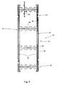
- a front view of tie 60 is shown in Fig. 5 .
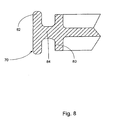
- Tie 60 is vertically elongated and includes a pair of rails 70, 72 interconnected by spacing members 66. Each rail comprises an inner runner 80 and an outer runner 82. The inner and outer runners 80, 82 are connected by a web 84 as seen best in Fig. 8 .
- the outer runner 82 comprises an engagement element by virtue of its T-shaped cross section, as explained more fully below.
- the spacing members 66 include depressions or notches 68 which when the insulating concrete form is assembled to form a hollow wall, provides horizontal supports for reinforcing bars that will be embedded in the concrete wall upon completion of the wall.
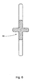
- the spacing members 66 have a cross section as shown in Fig. 6 .
- the tie 60 has an upper section 74, a middle section 76, and a lower section 78.
- Upper and lower sections 74, 78 are identical but are inverted. As will be seen in Fig. 5 , the upper and lower sections 74 and 78 have a cross-section that is 1-shaped; the middle section 76 has a T-shaped cross-section. Removal of the inner runner in middle section 76 facilitates slidable movement of the runners of tie 60 when inserted into C-channel 32 of anchors 20, 22.
- the tie 60 is shown in a side view in Fig. 7 and attention is drawn to slidable locking means comprising locking tabs or detents 90, 92 at the upper section 74 and lower section 78, respectively, of each of the rails 70.
- locking tabs 90, 92 are explained in greater detail below.
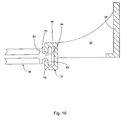
- FIGs 9 and 10 illustrate the engagement of the tie 60 with the anchors 20, 22.
- Anchors 20, 22 are embedded in panels 14, 12, respectively, such that the opening to the C-channel 32 (the space between the arms 34) is flush with the inner surface of panels 12, 14.
- the outer runner 82 is inserted into the opening of C-channel 32 and is thus locked in position and resists forces tending to push panels 12, 14 away from one another as is the condition when wet cement is being poured.
- Fig. 9 also illustrates that the outer surfaces of panels 12, 14 are outwardly spaced from the outer surface of furring strips 25 although as will be apparent to those skilled in the art, the furring strips may be closer to or flush with the outer surface of the panels.
- the workmen installing covering on the completed wall can easily identify the position of the furring strips so that a fastener, for example, may be attached through an outer covering to the panel by engaging and piercing the furring strip.
- a fastener for example, may be attached through an outer covering to the panel by engaging and piercing the furring strip.
- the panel may be molded so that it has vertical lines 27 that indicate the position of the furring strip beneath the outer surface of the panel.
- the furring strips be inset from the outer surface of the panel so that when an outer covering is positioned on the panel and a workman drives a fastener through the outer covering and into the furring strip, the panel in the immediate area of the fastener will be slightly compressed and thus provide a resistance force to assure contact between the outer covering and the panel.
- Figs. 11 and 12 show a portion of the upper section 74 of tie 60.
- Fig. 11 is a front view of the upper portion of the tie and
- Fig. 12 is a side elevation view of the portion shown in Fig. 11 .
- the top most section of the tie rail is formed so that the inner runner 80 flares toward the center of the panel away from outer runner 82 as shown at 100.
- the portion of outer runner 82, laterally adjacent the flared inner runner 100 is pointed as shown at 102.
- the purpose of the flare section 100 and pointed section 102 of the inner and outer runners, respectively, is to ease the entry of the rail runner 82 into the C-channel 32 of the anchor.
- tie 60 when tie 60 is inserted into the anchors as shown best in Figs. 1 and 9 , the tie may be locked vertically in place so that it does not disengage from the anchors.
- means for selectively preventing slidable movement between the tie and anchors The upper section 74 is identical to the lower section 78 except that the position of the elements are inverted. Referring now to the lower portion of Figs.
- one embodiment of the slidable preventing means comprises a locking tab 90 formed from outer runner 82 that terminates at 94 on one edge of the outer runner while the opposite edge of the runner includes a projection 92 that extends laterally beyond the edge of outer runner 82 and is sloped as shown at 96.
- the web 84 is notched at 104 so that the outer runner portion 92 is cantilevered and is thus free to deflect.
- the notch 104 removes a portion of web 84 immediately adjacent projection 92 and extending downward so as to terminate at 106 thereby defining an opening 108 in runner 82. This opening also allows outer runner portion 92 to freely deflect.
- the tip of outer runner 82 of tie 60 is inserted into C-channel 32 at one end.
- the tie is then slid in the C-channel whereby the sloped portion 96 of locking tab 90 as it passes each C-section 42, 44 is deflected.
- the locking tab 90 passes the lowest most arm section 42 on the left side of C-channel 32.
- the upper locking tab 90 enters the uppermost opening in arm 34 on the right side of C-channel 32. If the tie is then attempted to be removed from the anchors, the edges 98 of tabs 90 will engage the adjacent arm section 42 of the opening 108 and preclude the tie from sliding movement.
- the tie is slidably locked in place and when the tie is forced downwardly as will occur when rebar is laid in the notches of the spacing member 66, the load of the rebar will be resisted and will prevent inadvertent movement of the tie relative to the panels making up the form.
- the embodiment shown and described utilizes a male engagement element on the tie and a female engagement element in the anchor.
- the male-female relationship could be reversed if so desired.
- the engagement elements are shaped in cross-section as a "C” and a "T,” those skilled in the art will understand that various types of longitudinal engaging elements may be substituted for the "C” and "T” sections.
- the slidable locking or prevention means is only exemplary of sub-assemblies that may lock the slidable movement of one member relative to another including clips, fasteners, detent devices, glue, magnets or the like.
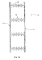
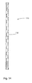
- a tie embodiment 110 with a male rail on one side and a female anchor at the other side as shown in Figs. 13 , 14 and 15 .
- the rail 112 is a female and has the same construction as the engaging member or element 26 of anchor 20 as shown and described in Figs. 2 and 4 .
- At the other side of the tie extender there is a standard rail of the type shown in Figs.
- the extension is 10.2 cm. (4 inches) in width, it may be used together with a standard tie also 10.2 cm. (4 inches) in width to build a 20.4 cm. (8 inch) wall.
- One 10.2 cm. (4 inch) extender, one 15.2 cm. (6 inch) extender, and one 10.2 cm. (4 inch) tie will build a 35.6 cm. (14 inch) thick wall.
- ties of 10.2 cm. (4 inch) and 15.2 cm. (6 inch) plus extenders of 10.2 cm. (4 inch) and 15.2 cm. (6 inch) will allow the building of a hollow wall in 5.1 cm. (2 inch) increments that may be used to construct walls of from 10.2 cm. - 61 cm. (4 to 24 inches) in thickness.
Landscapes
- Engineering & Computer Science (AREA)
- Architecture (AREA)
- Physics & Mathematics (AREA)
- Electromagnetism (AREA)
- Civil Engineering (AREA)
- Structural Engineering (AREA)
- Forms Removed On Construction Sites Or Auxiliary Members Thereof (AREA)
- Finishing Walls (AREA)
- Macromonomer-Based Addition Polymer (AREA)
- On-Site Construction Work That Accompanies The Preparation And Application Of Concrete (AREA)
- Building Environments (AREA)
Claims (15)
- Isolierende Betonform (10), die aufweist:zwei Platten (12, 14), die voneinander beabstandet angeordnet sind,wobei jede Platte aus einem leichten isolierenden Material hergestellt ist und eine Innenfläche und eine Außenfläche besitzt und die Innenflächen einander gegenüberliegen, undmindestens zwei senkrecht angeordnete Verbindungsanordnungen,die jeweils umfassen:zwei Anker (22, 22), die jeweils in senkrechter Richtung länglich ausgebildet und in senkrechter Richtung in einer der Platten eingebettet sind, wobei jeder Anker ein sich in senkrechter Richtung erstreckendes erstes Eingriffselement (26) aufweist, das so angeordnet ist, dass es auf der Innenfläche der Platte freiliegt, und einen länglichen Abstandshalter-Streifen (25), der angrenzend an die Außenfläche der Platte angeordnet ist, wobei das erste Eingriffselement durch mindestens ein Stegelement (28) mit dem länglichen Abstandshalter-Streifen verbunden ist, undein sich in senkrechter Richtung erstreckendes leiterartiges Verbindungselement (24), das mindestens ein Querelement (66) und ein Paar von sich in senkrechter Richtung erstreckenden zweiten Eingriffselementen (70, 72) umfasst, wobei jedes zweite Eingriffselement lösbar mit einem der ersten Eingriffselemente in Eingriff zu bringen ist, um so die Platten in einem Abstand voneinander zu halten,dadurch gekennzeichnet, dass die isolierende Betonform zusätzlich einen verschiebbaren Verriegelungsmechanismus aufweist, um ein Lösen des Ankers und des Verbindungselements zu verhindern, wobei der verschiebbare Verriegelungsmechanismus aufweist:ein weibliches Eingriffselement (32), welches das erste oder das zweite Eingriffselement vorgibt, wobei das weibliche Eingriffselement einen allgemein C-förmigen Querschnitt und längliche, gegenüberliegende Seiten aufweist, wobei jede Seite versetzte Öffnungen besitzt, die so angeordnet sind, dass sie im Wesentlichen mindestens einem Abschnitt einer der länglichen Seiten gegenüberliegen, undein männliches Eingriffselement (70, 72), welches das andere erste oder zweite Eingriffselement vorgibt, wobei das männliche Eingriffselement eine vorstehende Verriegelungsleiste (90, 92) aufweist, die so ausgebildet ist, dass sie sich gegen die gegenüberliegenden Seiten anlegt, wenn die vorstehende Verriegelungsleiste in das weibliche Eingriffselement (32) eingeschoben wird, und dort in einer der versetzten Öffnungen des weiblichen Eingriffselements verriegelt wird.
- Isolierende Betonform wie in Anspruch 1 beansprucht,
dadurch gekennzeichnet, dass die ersten Eingriffselemente insgesamt ein männliches oder ein weibliches Eingriffselement sind und die zweiten Eingriffselemente das andere männliche oder weibliche Eingriffselement darstellen. - Isolierende Betonform wie in Anspruch 1 beansprucht,
dadurch gekennzeichnet, dass jedes Verbindungselement (24) sowohl ein männliches als auch ein weibliches Eingriffselement aufweist, so dass mehr als ein Verbindungselement zwischen den beiden Ankern in Eingriff gebracht werden kann. - Isolierende Betonform wie in einem der vorhergehenden Ansprüche beansprucht, dadurch gekennzeichnet, dass das weibliche Eingriffselement einen C-förmigen Kanal (32) besitzt und das männliche Eingriffselement eine T-förmige Gleitschiene (82) aufweist, die verschiebbar in den C-förmigen Kanal einschiebbar ist.
- Isolierende Betonform wie in Anspruch 4 beansprucht,
dadurch gekennzeichnet, dass das Ende (48) des C-förmigen Kanals (32), die T-förmige Gleitschiene oder beide so geformt sind, dass ein gleitendes Einschieben der T-förmigen Gleitschiene in den C-förmigen Kanal erleichtert wird. - Isolierende Betonform wie in Anspruch 5 beansprucht,
dadurch gekennzeichnet, dass das Ende des C-förmigen Kanals (32) eine Aufweitung (48) besitzt, um das Einschieben der T-förmigen Gleitschiene (82) zu erleichtern. - Isolierende Betonform wie in Anspruch 5 oder Anspruch 6 beansprucht, dadurch gekennzeichnet, das das Ende der T-förmigen Gleitschiene (82) zugespitzt ist, um das Einschieben in den C-förmigen Kanal zu erleichtern.
- Isolierende Betonform wie in einem der vorhergehenden Ansprüche beansprucht, dadurch gekennzeichnet, dass die vorstehende Verriegelungsleiste so geformt ist, dass sie durch mehrere der versetzten Öffnungen einschiebbar ist.
- Isolierende Betonform wie in Anspruch 8 beansprucht,
dadurch gekennzeichnet, dass das männliche Eingriffselement (70, 72) zwei vorstehende Verriegelungsleisten (90, 92) aufweist, wobei eine davon eine Aufwärtsbewegung und die andere eine Abwärtsbewegung verhindert, nachdem sie in die entsprechenden versetzten Öffnungen im weiblichen Eingriffselement (32) eingesetzt wurden. - Isolierende Betonform wie in einem der vorhergehenden Ansprüche beansprucht, dadurch gekennzeichnet, dass die Höhe jedes ersten Eingriffselements (26) ungefähr gleich der Höhe der beiden Platten (12, 14) ist.
- Isolierende Betonform wie in einem der vorhergehenden Ansprüche beansprucht, dadurch gekennzeichnet, dass die Höhe jedes zweiten Eingriffselements (70, 72) ungefähr gleich der Höhe der beiden Platten (12, 14) ist.
- Isolierende Betonform wie in einem der vorhergehenden Ansprüche beansprucht, dadurch gekennzeichnet, dass der Abstandshalter-Streifen (25) in einer der Platten (12, 14) eingebettet ist oder auf ihrer Außenfläche freiliegt.
- Verfahren zum Aufbau einer isolierenden Wand, das umfasst:Anordnen von zwei isolierenden Platten (12, 14) in der Weise, dass ihre Innenflächen einander gegenüberliegen, wobei jede Platte einen in senkrechter Richtung angeordneten länglichen Anker (20, 22) aufweist, der senkrecht darin eingebettet ist, wobei jeder Anker ein sich in senkrechter Richtung erstreckendes erstes Eingriffselement (26), das auf der Innenfläche der Platte freiliegt, und einen länglichen Abstandshalter-Streifen (25) aufweist, der angrenzend an die Außenfläche der Platte angeordnet ist, wobei das erste Eingriffselement durch mindestens ein Stegelement (28) mit dem länglichen Abstandshalter-Streifen verbunden ist,Vorsehen mindestens eines leiterartigen Verbindungselements (24), wobei jedes Verbindungselement mindestens ein Querelement (66) und ein Paar von sich in senkrechter Richtung erstreckenden zweiten Eingriffselementen (70, 72) umfasst, wobei jedes zweite Eingriffselement mit einem ersten Eingriffselement in Eingriff zu bringen ist, um so die Platten in einem Abstand voneinander zu halten,Vorsehen eines verschiebbaren Verriegelungsmechanismus, um ein Lösen des Ankers und des Verbindungselements zu verhindern, wobei der verschiebbare Verriegelungsmechanismus aufweist:ein weibliches Eingriffselement (32), welches das erste oder das zweite Eingriffselement vorgibt, wobei das weibliche Eingriffselement einen allgemein C-förmigen Querschnitt und längliche, gegenüberliegende Seiten aufweist, wobei jede Seite versetzte Öffnungen besitzt, die so angeordnet sind, dass sie im Wesentlichen mindestens einem Abschnitt einer der länglichen Seiten gegenüberliegen, und ein männliches Eingriffselement (70, 72), welches das andere erste oder zweite Eingriffselement vorgibt, wobei das männliche Eingriffselement eine vorstehende Verriegelungsleiste (90, 92) aufweist, die so ausgebildet ist, dass sie sich gegen die gegenüberliegenden Seiten anlegt, wenn die vorstehende Verriegelungsleiste in das weibliche Eingriffselement (32) eingeschoben wird, und dort in einer der versetzten Öffnungen des weiblichen Eingriffselements verriegelt wird, undTransportieren der Platten mit nicht mit den Verbindungselementen in Eingriff befindlichen Ankern, um eine "zerlegte" Form vorzugeben.
- Verfahren wie in Anspruch 13 beansprucht, das ferner das Ineingriffbringen der Anker (20, 22) und der Verbindungselemente (24) vor Ort umfasst, um eine Form mit isolierender Wand und mit einem Hohlraum zu erzeugen, und Füllen des Hohlraums, um eine dauerhafte Wand zu erzeugen, die Beton und isolierende Platten umfasst.
- Verfahren wie in Anspruch 13 oder 14 beansprucht, das ferner umfasst:Ineingriffbringen eines ersten Ankers mit einem männlichen Eingriffselement eines ersten Verbindungselements,Ineingriffbringen eines weiblichen Eingriffselements des ersten Verbindungselements mit einem männlichen Eingriffselement eines zweiten Verbindungselements,Ineingriffbringen eines weiblichen Eingriffselements des zweiten Verbindungselements mit einem zweiten Anker, wobei der erste Anker und der zweite Anker einander gegenüber liegen und voneinander beabstandet sind.
Applications Claiming Priority (3)
| Application Number | Priority Date | Filing Date | Title |
|---|---|---|---|
| US75824106P | 2006-01-11 | 2006-01-11 | |
| US11/618,980 US7827752B2 (en) | 2006-01-11 | 2007-01-02 | Insulating concrete form having locking mechanism engaging tie with anchor |
| PCT/US2007/060042 WO2008136819A1 (en) | 2006-01-11 | 2007-01-03 | Insulating concrete form |
Publications (3)
| Publication Number | Publication Date |
|---|---|
| EP2010734A1 EP2010734A1 (de) | 2009-01-07 |
| EP2010734A4 EP2010734A4 (de) | 2009-05-27 |
| EP2010734B1 true EP2010734B1 (de) | 2011-10-26 |
Family
ID=39943789
Family Applications (1)
| Application Number | Title | Priority Date | Filing Date |
|---|---|---|---|
| EP07873295A Not-in-force EP2010734B1 (de) | 2006-01-11 | 2007-01-03 | Isolierende betonform |
Country Status (5)
| Country | Link |
|---|---|
| US (1) | US7827752B2 (de) |
| EP (1) | EP2010734B1 (de) |
| AT (1) | ATE530724T1 (de) |
| CA (1) | CA2635776C (de) |
| WO (1) | WO2008136819A1 (de) |
Families Citing this family (56)
| Publication number | Priority date | Publication date | Assignee | Title |
|---|---|---|---|---|
| MX2009008130A (es) * | 2007-02-02 | 2009-10-20 | Materiaux De Construction Oldc | Pared con acabado decorativo. |
| US9206599B2 (en) * | 2007-02-02 | 2015-12-08 | Les Materiaux De Construction Oldcastle Canada, Inc. | Wall with decorative facing |
| ITTO20070214A1 (it) * | 2007-03-26 | 2008-09-27 | Pontarolo Engineering Spa | Cassero a perdere per murature termicamente isolate in cemento armato. |
| DE202007016649U1 (de) * | 2007-04-02 | 2008-04-30 | Technoform Caprano Und Brunnhofer Gmbh & Co. Kg | Leiterförmiger Isoliersteg für ein Verbundprofil für Fenster-, Türen- und Fassadenelemente und Verbundprofil für Fenster-, Türen- und Fassadenelemente |
| MX2010003819A (es) | 2007-11-08 | 2010-04-30 | Keystone Retaining Wall System | Bloque de pared con almohadillas de soporte de peso y metodo de produccion de bloques de pared. |
| US8567750B2 (en) * | 2008-01-11 | 2013-10-29 | Victor Amend | Device having both non-abrading and fire-resistant properties for linking concrete formwork panels |
| US10533331B2 (en) | 2008-04-03 | 2020-01-14 | Paladin Industrial Llc | Concrete wall forming system and method thereof |
| US8348224B2 (en) * | 2008-04-03 | 2013-01-08 | Paladin Industrial, Llc | Tie system for forming poured concrete walls over concrete footings |
| US8424835B2 (en) * | 2008-04-03 | 2013-04-23 | Paladin Industrial, Llc | Method of supporting panel structures over concrete footings utilizing tie system for forming poured concrete walls |
| US9260874B2 (en) * | 2008-04-03 | 2016-02-16 | Paladin Industrial, Llc | Wall forming system and method thereof |
| US9091055B2 (en) * | 2008-08-19 | 2015-07-28 | Sonoma Cast Stone Corporation | Wall assembly method |
| EP2337908A1 (de) * | 2008-10-24 | 2011-06-29 | 2158484 Ontario Inc. | Betonformmodul und betonplattenstrukturen |
| GB0909280D0 (en) | 2009-06-01 | 2009-07-15 | Ciba Holding Inc | Wall form system |
| CA2773448C (en) * | 2009-09-29 | 2018-03-06 | Keystone Retaining Wall Systems, Inc. | Wall blocks, veneer panels for wall blocks and method of constructing walls |
| US8997421B2 (en) | 2009-12-08 | 2015-04-07 | Jose Javier Cerame | Holding units for stay in place molds |
| WO2011139784A2 (en) * | 2010-04-27 | 2011-11-10 | Buildblock Building Systems, Llc | Web structure for knockdown insulating concrete block |
| CN102869841B (zh) * | 2010-04-30 | 2015-05-20 | Ambe工程股份有限公司 | 用于形成隔热混凝土热质墙体的系统 |
| SG188449A1 (en) * | 2010-09-09 | 2013-04-30 | Buildgreen Asia Pte Ltd | Accessories for modular wall construction and method for constructing a modular wall |
| US9441342B2 (en) * | 2010-09-28 | 2016-09-13 | Les Materiaux De Construction Oldcastle Canada, In | Retaining wall |
| US9670640B2 (en) * | 2010-09-28 | 2017-06-06 | Les Materiaux De Construction Oldcastle Canada, Inc. | Retaining wall |
| EP2622141B1 (de) * | 2010-09-28 | 2023-06-14 | Les Matériaux de Construction Oldcastle Canada, Inc. | Stützwand |
| FR2974586B1 (fr) * | 2011-04-26 | 2016-10-28 | Lafarge Sa | Coffrage perdu pour mur en beton |
| MX387293B (es) * | 2011-06-03 | 2025-03-18 | Hercutech Inc | Sistema de muro reforzado. |
| US8720160B1 (en) | 2011-09-14 | 2014-05-13 | Alan Brian Cooper | Process for forming concrete walls and other vertically positioned shapes |
| US20140000199A1 (en) * | 2012-07-02 | 2014-01-02 | Integrated Structures, Inc. | Internally Braced Insulated Wall and Method of Constructing Same |
| WO2014042502A1 (es) * | 2012-09-17 | 2014-03-20 | Eleven Solutions Rfe S.A. De C.V. | Sistema constructivo modular de cimbra o encofrado permanente multiperforado para concreto u hormigón armado. |
| MX357232B (es) | 2012-11-30 | 2018-06-13 | Eleven Solutions Rfe S A De C V | Sistema constructivo ecologico para edificaciones con muros verdes. |
| WO2014127486A1 (en) | 2013-02-25 | 2014-08-28 | Les Materiaux De Construction Oldcastle Canada Inc. | Wall assembly |
| US9091089B2 (en) | 2013-03-12 | 2015-07-28 | Icf Mform Llc | Insulating concrete form (ICF) system with tie member modularity |
| US9175486B2 (en) | 2013-03-12 | 2015-11-03 | Icf Mform Llc | Insulating concrete form (ICF) system with modular tie members and associated ICF tooling |
| SI24399A (sl) | 2013-05-30 | 2014-12-31 | Intech-Les, Razvojni Center D.O.O. | Postopek vgradnje nosilne stene z obojestransko toplotno izolacijo |
| EP2843146B1 (de) * | 2013-08-29 | 2017-10-04 | Loimaan Kivi Oy | Wandblockelement |
| US10907348B2 (en) | 2013-11-07 | 2021-02-02 | Csr Building Products Limited | Building component |
| AU2017101421A4 (en) * | 2013-11-07 | 2017-11-23 | Csr Building Products Limited | Building Component |
| CN111576724B (zh) * | 2013-11-07 | 2022-06-07 | Csr建筑产品有限公司 | 建筑部件 |
| CA2929964C (en) * | 2013-12-07 | 2022-08-09 | Dean Holding Corporation | Bridge system for multi-stage walls |
| WO2016059357A1 (en) * | 2014-10-15 | 2016-04-21 | Twinwall Icf Limited | A formwork system |
| WO2016154670A1 (en) * | 2015-03-27 | 2016-10-06 | Ambe Engineering Pty Ltd | System for forming an insulated structural concrete wall |
| USD814911S1 (en) | 2016-07-21 | 2018-04-10 | Keystone Retaining Wall Systems Llc | Connector |
| USD815938S1 (en) | 2016-07-21 | 2018-04-24 | Keystone Retaining Wall Systems Llc | Connector |
| WO2018017656A1 (en) | 2016-07-21 | 2018-01-25 | Keystone Retaining Wall Systems Llc | Veneer connectors, wall blocks, veneer panels for wall blocks, and walls |
| USD812781S1 (en) | 2016-07-21 | 2018-03-13 | Keystone Retaining Wall Systems Llc | Wall block |
| USD814278S1 (en) | 2016-07-21 | 2018-04-03 | Keystone Retaining Wall Systems Llc | Connector |
| US11248383B2 (en) | 2018-09-21 | 2022-02-15 | Cooper E. Stewart | Insulating concrete form apparatus |
| US11352787B2 (en) * | 2019-06-18 | 2022-06-07 | Victor Amend | Concrete form panel, and concrete formwork comprising same |
| US20220228384A1 (en) * | 2021-01-21 | 2022-07-21 | Richard White | Stem Wall Bracket System and Method |
| US12104375B2 (en) * | 2021-03-01 | 2024-10-01 | Logix Brands Ltd. | Concrete form assembly |
| US11668089B2 (en) * | 2021-03-01 | 2023-06-06 | Logix Brands Ltd | Concrete form assembly |
| US12044018B2 (en) * | 2021-03-01 | 2024-07-23 | Logix Brands Ltd. | Concrete form assembly |
| US12084858B2 (en) * | 2021-03-01 | 2024-09-10 | Logix Brands Ltd. | Concrete form assembly |
| CN113605691A (zh) * | 2021-08-26 | 2021-11-05 | 晟通科技集团有限公司 | 模板连接件及模板系统 |
| CN114016727A (zh) * | 2021-12-01 | 2022-02-08 | 晟通科技集团有限公司 | 模板固定件及模板结构 |
| USD1115068S1 (en) * | 2022-10-05 | 2026-02-24 | Izodom 2000 Polska Spolka Z Ograniczona Odpowiedzialnoscia | Insulation block |
| KR102565971B1 (ko) * | 2023-05-02 | 2023-08-10 | (주)에코이노텍 | Pc 더블월 구조물 및 그 시공 방법 |
| PT119642B (pt) | 2024-08-05 | 2025-01-06 | Paulo Jorge Ribeiro Lourenco | Dispositivo espaçador e sistema para construção incremental de painéis para execução de elementos estruturais de construção |
| CN120061499B (zh) * | 2025-04-02 | 2025-08-15 | 扬中市华龙橡塑电器有限公司 | 一种免拆复合保温模板 |
Family Cites Families (55)
| Publication number | Priority date | Publication date | Assignee | Title |
|---|---|---|---|---|
| US510720A (en) * | 1893-12-12 | Tile building-wall | ||
| US1345156A (en) * | 1919-02-17 | 1920-06-29 | Flynn Dennis John | Cementitious structure |
| US1953287A (en) * | 1930-02-19 | 1934-04-03 | Bemis Ind Inc | Building construction |
| US2316819A (en) * | 1940-10-15 | 1943-04-20 | Roy B Tedrow | Wall structure |
| US2326361A (en) * | 1941-08-22 | 1943-08-10 | Lock Seal Company | Building construction |
| US2647392A (en) * | 1950-03-15 | 1953-08-04 | Howe E Wilson | Building block with spaced walls |
| US3992844A (en) * | 1975-08-28 | 1976-11-23 | Joseph Clemens Gretter | Building panel |
| US4118004A (en) * | 1977-05-16 | 1978-10-03 | Samuel Clyde Scott | Concrete beam form |
| CA1092846A (en) * | 1977-10-05 | 1981-01-06 | William D. Lount | Foamed plastic concrete form and connectors therefor |
| AU528357B2 (en) * | 1977-12-15 | 1983-04-28 | La Grouw, Johannes | Improvements in or relating to building planks and/or methods and/or apparatus for making thesame |
| US4223501A (en) * | 1978-12-29 | 1980-09-23 | Rocky Mountain Foam Form, Inc. | Concrete form |
| US4439967A (en) * | 1982-03-15 | 1984-04-03 | Isorast Thermacell (U.S.A.), Inc. | Apparatus in and relating to building formwork |
| US4765109A (en) * | 1987-09-25 | 1988-08-23 | Boeshart Patrick E | Adjustable tie |
| US4889310A (en) * | 1988-05-26 | 1989-12-26 | Boeshart Patrick E | Concrete forming system |
| US5337530A (en) * | 1989-10-13 | 1994-08-16 | Beames Douglas M | Building wall construction |
| US5209039A (en) * | 1992-04-10 | 1993-05-11 | Boeshart Patrick E | Apparatus for interconnecting concrete wall forms |
| US5367845A (en) * | 1993-02-09 | 1994-11-29 | Hartling; Robert H. | System for building a structure |
| US5390459A (en) * | 1993-03-31 | 1995-02-21 | Aab Building System Inc. | Concrete form walls |
| US5321926A (en) * | 1993-05-24 | 1994-06-21 | Kennedy Francis A | Building block |
| US5459971A (en) * | 1994-03-04 | 1995-10-24 | Sparkman; Alan | Connecting member for concrete form |
| JP3570723B2 (ja) * | 1994-05-10 | 2004-09-29 | クワド−ロック ビルディング システムズ リミテッド | 連結された複数のフォーム・パネルを使用する絶縁コンクリート型枠 |
| US5657600A (en) * | 1994-06-20 | 1997-08-19 | Aab Building Systems Inc. | Web member for concrete form walls |
| US5625989A (en) * | 1995-07-28 | 1997-05-06 | Huntington Foam Corp. | Method and apparatus for forming of a poured concrete wall |
| US5701710A (en) * | 1995-12-07 | 1997-12-30 | Innovative Construction Technologies Corporation | Self-supporting concrete form module |
| US5735093A (en) * | 1996-02-13 | 1998-04-07 | Grutsch; George A. | Concrete formwork with backing plates |
| US6978581B1 (en) * | 1997-02-04 | 2005-12-27 | Pentstar Corporation | Composite building block with connective structure |
| US5983585A (en) * | 1997-02-04 | 1999-11-16 | Spakousky; John | Building block with insulating center portion |
| US5896714A (en) * | 1997-03-11 | 1999-04-27 | Cymbala; Patrick M. | Insulating concrete form system |
| CA2209251C (en) * | 1997-07-04 | 2001-10-02 | Frank B. Bentley | Form system |
| NZ329387A (en) * | 1997-12-12 | 1999-02-25 | Grouw Holdings Ltd | Building member comprising two spaced apart boards and at least one connecting member |
| US6481178B2 (en) * | 1998-01-16 | 2002-11-19 | Eco-Block, Llc | Tilt-up wall |
| US6438918B2 (en) * | 1998-01-16 | 2002-08-27 | Eco-Block | Latching system for components used in forming concrete structures |
| US5992114A (en) * | 1998-04-13 | 1999-11-30 | Zelinsky; Ronald Dean | Apparatus for forming a poured concrete wall |
| US6694692B2 (en) * | 1998-10-16 | 2004-02-24 | Francesco Piccone | Modular formwork elements and assembly |
| US6314694B1 (en) * | 1998-12-17 | 2001-11-13 | Arxx Building Products Inc. | One-sided insulated formwork |
| US6250024B1 (en) * | 1998-12-17 | 2001-06-26 | Robert Elias Sculthorpe | Temporary bracing system for insulated concrete form walls and method |
| CA2256091A1 (en) * | 1998-12-23 | 2000-06-23 | Jean-Louis Beliveau | Concrete wall form and connectors therefor |
| US6321497B1 (en) * | 1999-02-02 | 2001-11-27 | First Choice Manufacturing Ltd. | Web for insulated concrete form |
| CA2367016C (en) * | 1999-03-30 | 2010-06-15 | Arxx Building Products Inc. | Bridging member for concrete form walls |
| US6668503B2 (en) * | 1999-04-16 | 2003-12-30 | Polyform A.G.P. Inc. | Concrete wall form and connectors therefor |
| US6536172B1 (en) * | 1999-06-01 | 2003-03-25 | Victor A. Amend | Insulating construction form and manner of employment for same |
| US6318040B1 (en) * | 1999-10-25 | 2001-11-20 | James D. Moore, Jr. | Concrete form system and method |
| CA2298170A1 (en) * | 2000-02-11 | 2001-08-11 | Jean-Louis Beliveau | Stackable construction panel |
| US6240692B1 (en) * | 2000-05-26 | 2001-06-05 | Louis L. Yost | Concrete form assembly |
| US6820384B1 (en) * | 2000-10-19 | 2004-11-23 | Reward Wall Systems, Inc. | Prefabricated foam block concrete forms and ties molded therein |
| US6647686B2 (en) * | 2001-03-09 | 2003-11-18 | Daniel D. Dunn | System for constructing insulated concrete structures |
| US6935081B2 (en) * | 2001-03-09 | 2005-08-30 | Daniel D. Dunn | Reinforced composite system for constructing insulated concrete structures |
| CA2346328A1 (en) * | 2001-05-04 | 2002-11-04 | Jean-Louis Beliveau | Improvements in a stackable construction panel system |
| US20030070379A1 (en) * | 2001-10-12 | 2003-04-17 | Wall-Ties & Forms, Inc. | Attachment element for use with concrete wall and method employing same |
| US7082731B2 (en) * | 2002-09-03 | 2006-08-01 | Murray Patz | Insulated concrete wall system |
| US7415804B2 (en) * | 2002-09-05 | 2008-08-26 | Coombs Jerry D | Isulated concrete form having welded wire form tie |
| US6915613B2 (en) * | 2002-12-02 | 2005-07-12 | Cellox Llc | Collapsible concrete forms |
| AT7060U1 (de) | 2003-02-28 | 2004-09-27 | Tomaschitz Heimo | Wand- bzw. isolationswandkonstruktion |
| CZ20032141A3 (cs) * | 2003-08-06 | 2005-05-18 | Canstroy Cz, S. R. O. | Systém izolačního bednění pro betonovou stěnu a kloubově uložené rozpěrné spojovací žebro |
| US7409801B2 (en) * | 2004-03-16 | 2008-08-12 | Tritex Icf Products, Inc. | Prefabricated foam block concrete forms with open tooth connection means |
-
2007
- 2007-01-02 US US11/618,980 patent/US7827752B2/en not_active Expired - Fee Related
- 2007-01-03 WO PCT/US2007/060042 patent/WO2008136819A1/en not_active Ceased
- 2007-01-03 CA CA2635776A patent/CA2635776C/en active Active
- 2007-01-03 EP EP07873295A patent/EP2010734B1/de not_active Not-in-force
- 2007-01-03 AT AT07873295T patent/ATE530724T1/de not_active IP Right Cessation
Also Published As
| Publication number | Publication date |
|---|---|
| US7827752B2 (en) | 2010-11-09 |
| WO2008136819A1 (en) | 2008-11-13 |
| CA2635776C (en) | 2015-10-20 |
| US20080022619A1 (en) | 2008-01-31 |
| CA2635776A1 (en) | 2007-07-11 |
| EP2010734A4 (de) | 2009-05-27 |
| ATE530724T1 (de) | 2011-11-15 |
| EP2010734A1 (de) | 2009-01-07 |
Similar Documents
| Publication | Publication Date | Title |
|---|---|---|
| US7827752B2 (en) | Insulating concrete form having locking mechanism engaging tie with anchor | |
| US6164035A (en) | Reinforced foam block wall | |
| US8037652B2 (en) | Insulated concrete form | |
| US5861105A (en) | Concrete form system | |
| US8458969B2 (en) | Stay-in-place form systems for form-work edges, windows and other building openings | |
| CA2773966C (en) | High strength adjustable vertical concrete form | |
| US6739102B2 (en) | Method and apparatus for forming a concrete foundation wall | |
| US6318040B1 (en) | Concrete form system and method | |
| US6336301B1 (en) | Concrete form system ledge assembly and method | |
| US10753109B2 (en) | Concrete form tie, and concrete formwork comprising same | |
| US20110023402A1 (en) | Building Elements | |
| KR101795511B1 (ko) | 건축용 데크패널 | |
| CA3014571C (en) | Concrete form tie, and concrete formwork comprising same | |
| US20040159061A1 (en) | Insulated concrete form system and method for use | |
| US12044018B2 (en) | Concrete form assembly | |
| US20100018144A1 (en) | Wall system and method with integral channel | |
| WO2006129394A1 (ja) | 型枠兼用断熱パネルおよびそれを用いた建築用型枠 | |
| WO1992002694A1 (en) | Construction joints | |
| JP4021404B2 (ja) | 型枠兼断熱建材およびその型枠兼断熱建材を使用した建築用型枠 | |
| US12104375B2 (en) | Concrete form assembly | |
| US12084858B2 (en) | Concrete form assembly | |
| JP2006070610A (ja) | コンクリート打設用型枠 | |
| JP2001200606A (ja) | 型枠および型枠工法 | |
| JP2008208692A (ja) | 高耐久コンクリート製躯体構造体。 |
Legal Events
| Date | Code | Title | Description |
|---|---|---|---|
| PUAI | Public reference made under article 153(3) epc to a published international application that has entered the european phase |
Free format text: ORIGINAL CODE: 0009012 |
|
| 17P | Request for examination filed |
Effective date: 20080811 |
|
| AK | Designated contracting states |
Kind code of ref document: A1 Designated state(s): AT BE BG CH CY CZ DE DK EE ES FI FR GB GR HU IE IS IT LI LT LU LV MC NL PL PT RO SE SI SK TR |
|
| AX | Request for extension of the european patent |
Extension state: AL BA HR MK RS |
|
| A4 | Supplementary search report drawn up and despatched |
Effective date: 20090423 |
|
| 17Q | First examination report despatched |
Effective date: 20090729 |
|
| GRAP | Despatch of communication of intention to grant a patent |
Free format text: ORIGINAL CODE: EPIDOSNIGR1 |
|
| DAX | Request for extension of the european patent (deleted) | ||
| GRAS | Grant fee paid |
Free format text: ORIGINAL CODE: EPIDOSNIGR3 |
|
| GRAA | (expected) grant |
Free format text: ORIGINAL CODE: 0009210 |
|
| AK | Designated contracting states |
Kind code of ref document: B1 Designated state(s): AT BE BG CH CY CZ DE DK EE ES FI FR GB GR HU IE IS IT LI LT LU LV MC NL PL PT RO SE SI SK TR |
|
| REG | Reference to a national code |
Ref country code: GB Ref legal event code: FG4D |
|
| REG | Reference to a national code |
Ref country code: CH Ref legal event code: EP |
|
| REG | Reference to a national code |
Ref country code: IE Ref legal event code: FG4D |
|
| REG | Reference to a national code |
Ref country code: DE Ref legal event code: R096 Ref document number: 602007018354 Country of ref document: DE Effective date: 20111222 |
|
| REG | Reference to a national code |
Ref country code: NL Ref legal event code: VDEP Effective date: 20111026 |
|
| LTIE | Lt: invalidation of european patent or patent extension |
Effective date: 20111026 |
|
| REG | Reference to a national code |
Ref country code: AT Ref legal event code: MK05 Ref document number: 530724 Country of ref document: AT Kind code of ref document: T Effective date: 20111026 |
|
| PG25 | Lapsed in a contracting state [announced via postgrant information from national office to epo] |
Ref country code: BE Free format text: LAPSE BECAUSE OF FAILURE TO SUBMIT A TRANSLATION OF THE DESCRIPTION OR TO PAY THE FEE WITHIN THE PRESCRIBED TIME-LIMIT Effective date: 20111026 Ref country code: IS Free format text: LAPSE BECAUSE OF FAILURE TO SUBMIT A TRANSLATION OF THE DESCRIPTION OR TO PAY THE FEE WITHIN THE PRESCRIBED TIME-LIMIT Effective date: 20120226 Ref country code: LT Free format text: LAPSE BECAUSE OF FAILURE TO SUBMIT A TRANSLATION OF THE DESCRIPTION OR TO PAY THE FEE WITHIN THE PRESCRIBED TIME-LIMIT Effective date: 20111026 |
|
| PG25 | Lapsed in a contracting state [announced via postgrant information from national office to epo] |
Ref country code: PL Free format text: LAPSE BECAUSE OF FAILURE TO SUBMIT A TRANSLATION OF THE DESCRIPTION OR TO PAY THE FEE WITHIN THE PRESCRIBED TIME-LIMIT Effective date: 20111026 Ref country code: SI Free format text: LAPSE BECAUSE OF FAILURE TO SUBMIT A TRANSLATION OF THE DESCRIPTION OR TO PAY THE FEE WITHIN THE PRESCRIBED TIME-LIMIT Effective date: 20111026 Ref country code: GR Free format text: LAPSE BECAUSE OF FAILURE TO SUBMIT A TRANSLATION OF THE DESCRIPTION OR TO PAY THE FEE WITHIN THE PRESCRIBED TIME-LIMIT Effective date: 20120127 Ref country code: SE Free format text: LAPSE BECAUSE OF FAILURE TO SUBMIT A TRANSLATION OF THE DESCRIPTION OR TO PAY THE FEE WITHIN THE PRESCRIBED TIME-LIMIT Effective date: 20111026 Ref country code: NL Free format text: LAPSE BECAUSE OF FAILURE TO SUBMIT A TRANSLATION OF THE DESCRIPTION OR TO PAY THE FEE WITHIN THE PRESCRIBED TIME-LIMIT Effective date: 20111026 Ref country code: LV Free format text: LAPSE BECAUSE OF FAILURE TO SUBMIT A TRANSLATION OF THE DESCRIPTION OR TO PAY THE FEE WITHIN THE PRESCRIBED TIME-LIMIT Effective date: 20111026 Ref country code: PT Free format text: LAPSE BECAUSE OF FAILURE TO SUBMIT A TRANSLATION OF THE DESCRIPTION OR TO PAY THE FEE WITHIN THE PRESCRIBED TIME-LIMIT Effective date: 20120227 |
|
| PG25 | Lapsed in a contracting state [announced via postgrant information from national office to epo] |
Ref country code: CY Free format text: LAPSE BECAUSE OF FAILURE TO SUBMIT A TRANSLATION OF THE DESCRIPTION OR TO PAY THE FEE WITHIN THE PRESCRIBED TIME-LIMIT Effective date: 20111026 |
|
| PG25 | Lapsed in a contracting state [announced via postgrant information from national office to epo] |
Ref country code: DK Free format text: LAPSE BECAUSE OF FAILURE TO SUBMIT A TRANSLATION OF THE DESCRIPTION OR TO PAY THE FEE WITHIN THE PRESCRIBED TIME-LIMIT Effective date: 20111026 Ref country code: EE Free format text: LAPSE BECAUSE OF FAILURE TO SUBMIT A TRANSLATION OF THE DESCRIPTION OR TO PAY THE FEE WITHIN THE PRESCRIBED TIME-LIMIT Effective date: 20111026 Ref country code: SK Free format text: LAPSE BECAUSE OF FAILURE TO SUBMIT A TRANSLATION OF THE DESCRIPTION OR TO PAY THE FEE WITHIN THE PRESCRIBED TIME-LIMIT Effective date: 20111026 Ref country code: CZ Free format text: LAPSE BECAUSE OF FAILURE TO SUBMIT A TRANSLATION OF THE DESCRIPTION OR TO PAY THE FEE WITHIN THE PRESCRIBED TIME-LIMIT Effective date: 20111026 Ref country code: BG Free format text: LAPSE BECAUSE OF FAILURE TO SUBMIT A TRANSLATION OF THE DESCRIPTION OR TO PAY THE FEE WITHIN THE PRESCRIBED TIME-LIMIT Effective date: 20120126 |
|
| PG25 | Lapsed in a contracting state [announced via postgrant information from national office to epo] |
Ref country code: IT Free format text: LAPSE BECAUSE OF FAILURE TO SUBMIT A TRANSLATION OF THE DESCRIPTION OR TO PAY THE FEE WITHIN THE PRESCRIBED TIME-LIMIT Effective date: 20111026 Ref country code: MC Free format text: LAPSE BECAUSE OF NON-PAYMENT OF DUE FEES Effective date: 20120131 Ref country code: RO Free format text: LAPSE BECAUSE OF FAILURE TO SUBMIT A TRANSLATION OF THE DESCRIPTION OR TO PAY THE FEE WITHIN THE PRESCRIBED TIME-LIMIT Effective date: 20111026 |
|
| PLBE | No opposition filed within time limit |
Free format text: ORIGINAL CODE: 0009261 |
|
| REG | Reference to a national code |
Ref country code: CH Ref legal event code: PL |
|
| STAA | Information on the status of an ep patent application or granted ep patent |
Free format text: STATUS: NO OPPOSITION FILED WITHIN TIME LIMIT |
|
| 26N | No opposition filed |
Effective date: 20120727 |
|
| REG | Reference to a national code |
Ref country code: IE Ref legal event code: MM4A |
|
| PG25 | Lapsed in a contracting state [announced via postgrant information from national office to epo] |
Ref country code: CH Free format text: LAPSE BECAUSE OF NON-PAYMENT OF DUE FEES Effective date: 20120131 Ref country code: DE Free format text: LAPSE BECAUSE OF NON-PAYMENT OF DUE FEES Effective date: 20120801 Ref country code: LI Free format text: LAPSE BECAUSE OF NON-PAYMENT OF DUE FEES Effective date: 20120131 |
|
| REG | Reference to a national code |
Ref country code: DE Ref legal event code: R119 Ref document number: 602007018354 Country of ref document: DE Effective date: 20120801 |
|
| REG | Reference to a national code |
Ref country code: DE Ref legal event code: R097 Ref document number: 602007018354 Country of ref document: DE Effective date: 20120727 |
|
| PG25 | Lapsed in a contracting state [announced via postgrant information from national office to epo] |
Ref country code: IE Free format text: LAPSE BECAUSE OF NON-PAYMENT OF DUE FEES Effective date: 20120103 Ref country code: AT Free format text: LAPSE BECAUSE OF FAILURE TO SUBMIT A TRANSLATION OF THE DESCRIPTION OR TO PAY THE FEE WITHIN THE PRESCRIBED TIME-LIMIT Effective date: 20111026 |
|
| PG25 | Lapsed in a contracting state [announced via postgrant information from national office to epo] |
Ref country code: ES Free format text: LAPSE BECAUSE OF FAILURE TO SUBMIT A TRANSLATION OF THE DESCRIPTION OR TO PAY THE FEE WITHIN THE PRESCRIBED TIME-LIMIT Effective date: 20120206 |
|
| PG25 | Lapsed in a contracting state [announced via postgrant information from national office to epo] |
Ref country code: FI Free format text: LAPSE BECAUSE OF FAILURE TO SUBMIT A TRANSLATION OF THE DESCRIPTION OR TO PAY THE FEE WITHIN THE PRESCRIBED TIME-LIMIT Effective date: 20111026 |
|
| PG25 | Lapsed in a contracting state [announced via postgrant information from national office to epo] |
Ref country code: TR Free format text: LAPSE BECAUSE OF FAILURE TO SUBMIT A TRANSLATION OF THE DESCRIPTION OR TO PAY THE FEE WITHIN THE PRESCRIBED TIME-LIMIT Effective date: 20111026 |
|
| PG25 | Lapsed in a contracting state [announced via postgrant information from national office to epo] |
Ref country code: LU Free format text: LAPSE BECAUSE OF NON-PAYMENT OF DUE FEES Effective date: 20120103 |
|
| PGFP | Annual fee paid to national office [announced via postgrant information from national office to epo] |
Ref country code: FR Payment date: 20140108 Year of fee payment: 8 |
|
| PGFP | Annual fee paid to national office [announced via postgrant information from national office to epo] |
Ref country code: GB Payment date: 20140102 Year of fee payment: 8 |
|
| PG25 | Lapsed in a contracting state [announced via postgrant information from national office to epo] |
Ref country code: HU Free format text: LAPSE BECAUSE OF FAILURE TO SUBMIT A TRANSLATION OF THE DESCRIPTION OR TO PAY THE FEE WITHIN THE PRESCRIBED TIME-LIMIT Effective date: 20070103 |
|
| GBPC | Gb: european patent ceased through non-payment of renewal fee |
Effective date: 20150103 |
|
| PG25 | Lapsed in a contracting state [announced via postgrant information from national office to epo] |
Ref country code: GB Free format text: LAPSE BECAUSE OF NON-PAYMENT OF DUE FEES Effective date: 20150103 |
|
| REG | Reference to a national code |
Ref country code: FR Ref legal event code: ST Effective date: 20150930 |
|
| PG25 | Lapsed in a contracting state [announced via postgrant information from national office to epo] |
Ref country code: FR Free format text: LAPSE BECAUSE OF NON-PAYMENT OF DUE FEES Effective date: 20150202 |