EP2010757B1 - Aube de turbine - Google Patents
Aube de turbine Download PDFInfo
- Publication number
- EP2010757B1 EP2010757B1 EP07726359.8A EP07726359A EP2010757B1 EP 2010757 B1 EP2010757 B1 EP 2010757B1 EP 07726359 A EP07726359 A EP 07726359A EP 2010757 B1 EP2010757 B1 EP 2010757B1
- Authority
- EP
- European Patent Office
- Prior art keywords
- turbine blade
- blade
- medium
- trailing edge
- turbine
- Prior art date
- Legal status (The legal status is an assumption and is not a legal conclusion. Google has not performed a legal analysis and makes no representation as to the accuracy of the status listed.)
- Not-in-force
Links
- 238000002156 mixing Methods 0.000 claims description 43
- 239000000446 fuel Substances 0.000 claims description 18
- 238000007664 blowing Methods 0.000 claims description 8
- 238000011144 upstream manufacturing Methods 0.000 claims description 3
- 238000001816 cooling Methods 0.000 description 26
- 239000000203 mixture Substances 0.000 description 26
- 238000002485 combustion reaction Methods 0.000 description 15
- 239000002184 metal Substances 0.000 description 6
- 238000005266 casting Methods 0.000 description 5
- 206010016754 Flashback Diseases 0.000 description 3
- 230000000712 assembly Effects 0.000 description 3
- 238000000429 assembly Methods 0.000 description 3
- 238000004891 communication Methods 0.000 description 3
- 239000012530 fluid Substances 0.000 description 3
- 238000011065 in-situ storage Methods 0.000 description 3
- 239000000376 reactant Substances 0.000 description 3
- 239000000243 solution Substances 0.000 description 3
- 230000015572 biosynthetic process Effects 0.000 description 2
- 238000006243 chemical reaction Methods 0.000 description 2
- 239000002826 coolant Substances 0.000 description 2
- 238000013461 design Methods 0.000 description 2
- 210000003734 kidney Anatomy 0.000 description 2
- 238000000034 method Methods 0.000 description 2
- 230000010355 oscillation Effects 0.000 description 2
- 238000003303 reheating Methods 0.000 description 2
- 238000005476 soldering Methods 0.000 description 2
- 238000003466 welding Methods 0.000 description 2
- 239000000654 additive Substances 0.000 description 1
- 239000003795 chemical substances by application Substances 0.000 description 1
- 230000003247 decreasing effect Effects 0.000 description 1
- 238000009826 distribution Methods 0.000 description 1
- 230000000694 effects Effects 0.000 description 1
- 239000003344 environmental pollutant Substances 0.000 description 1
- 230000009969 flowable effect Effects 0.000 description 1
- 238000010438 heat treatment Methods 0.000 description 1
- 239000008240 homogeneous mixture Substances 0.000 description 1
- 238000002347 injection Methods 0.000 description 1
- 239000007924 injection Substances 0.000 description 1
- 238000003780 insertion Methods 0.000 description 1
- 230000037431 insertion Effects 0.000 description 1
- 238000009434 installation Methods 0.000 description 1
- 238000012423 maintenance Methods 0.000 description 1
- 238000004519 manufacturing process Methods 0.000 description 1
- 239000000463 material Substances 0.000 description 1
- 231100000719 pollutant Toxicity 0.000 description 1
- 238000002360 preparation method Methods 0.000 description 1
- 238000010926 purge Methods 0.000 description 1
- 230000035484 reaction time Effects 0.000 description 1
- 239000007787 solid Substances 0.000 description 1
- 125000006850 spacer group Chemical group 0.000 description 1
- 238000004804 winding Methods 0.000 description 1
Images


Classifications
-
- F—MECHANICAL ENGINEERING; LIGHTING; HEATING; WEAPONS; BLASTING
- F01—MACHINES OR ENGINES IN GENERAL; ENGINE PLANTS IN GENERAL; STEAM ENGINES
- F01D—NON-POSITIVE DISPLACEMENT MACHINES OR ENGINES, e.g. STEAM TURBINES
- F01D5/00—Blades; Blade-carrying members; Heating, heat-insulating, cooling or antivibration means on the blades or the members
- F01D5/12—Blades
- F01D5/14—Form or construction
- F01D5/141—Shape, i.e. outer, aerodynamic form
- F01D5/145—Means for influencing boundary layers or secondary circulations
-
- F—MECHANICAL ENGINEERING; LIGHTING; HEATING; WEAPONS; BLASTING
- F01—MACHINES OR ENGINES IN GENERAL; ENGINE PLANTS IN GENERAL; STEAM ENGINES
- F01D—NON-POSITIVE DISPLACEMENT MACHINES OR ENGINES, e.g. STEAM TURBINES
- F01D5/00—Blades; Blade-carrying members; Heating, heat-insulating, cooling or antivibration means on the blades or the members
- F01D5/12—Blades
- F01D5/14—Form or construction
- F01D5/18—Hollow blades, i.e. blades with cooling or heating channels or cavities; Heating, heat-insulating or cooling means on blades
- F01D5/186—Film cooling
-
- F—MECHANICAL ENGINEERING; LIGHTING; HEATING; WEAPONS; BLASTING
- F01—MACHINES OR ENGINES IN GENERAL; ENGINE PLANTS IN GENERAL; STEAM ENGINES
- F01D—NON-POSITIVE DISPLACEMENT MACHINES OR ENGINES, e.g. STEAM TURBINES
- F01D5/00—Blades; Blade-carrying members; Heating, heat-insulating, cooling or antivibration means on the blades or the members
- F01D5/12—Blades
- F01D5/14—Form or construction
- F01D5/18—Hollow blades, i.e. blades with cooling or heating channels or cavities; Heating, heat-insulating or cooling means on blades
- F01D5/187—Convection cooling
-
- F—MECHANICAL ENGINEERING; LIGHTING; HEATING; WEAPONS; BLASTING
- F01—MACHINES OR ENGINES IN GENERAL; ENGINE PLANTS IN GENERAL; STEAM ENGINES
- F01D—NON-POSITIVE DISPLACEMENT MACHINES OR ENGINES, e.g. STEAM TURBINES
- F01D9/00—Stators
- F01D9/06—Fluid supply conduits to nozzles or the like
- F01D9/065—Fluid supply or removal conduits traversing the working fluid flow, e.g. for lubrication-, cooling-, or sealing fluids
-
- F—MECHANICAL ENGINEERING; LIGHTING; HEATING; WEAPONS; BLASTING
- F02—COMBUSTION ENGINES; HOT-GAS OR COMBUSTION-PRODUCT ENGINE PLANTS
- F02C—GAS-TURBINE PLANTS; AIR INTAKES FOR JET-PROPULSION PLANTS; CONTROLLING FUEL SUPPLY IN AIR-BREATHING JET-PROPULSION PLANTS
- F02C3/00—Gas-turbine plants characterised by the use of combustion products as the working fluid
- F02C3/14—Gas-turbine plants characterised by the use of combustion products as the working fluid characterised by the arrangement of the combustion chamber in the plant
- F02C3/16—Gas-turbine plants characterised by the use of combustion products as the working fluid characterised by the arrangement of the combustion chamber in the plant the combustion chambers being formed at least partly in the turbine rotor or in an other rotating part of the plant
-
- F—MECHANICAL ENGINEERING; LIGHTING; HEATING; WEAPONS; BLASTING
- F02—COMBUSTION ENGINES; HOT-GAS OR COMBUSTION-PRODUCT ENGINE PLANTS
- F02K—JET-PROPULSION PLANTS
- F02K3/00—Plants including a gas turbine driving a compressor or a ducted fan
- F02K3/08—Plants including a gas turbine driving a compressor or a ducted fan with supplementary heating of the working fluid; Control thereof
-
- F—MECHANICAL ENGINEERING; LIGHTING; HEATING; WEAPONS; BLASTING
- F01—MACHINES OR ENGINES IN GENERAL; ENGINE PLANTS IN GENERAL; STEAM ENGINES
- F01D—NON-POSITIVE DISPLACEMENT MACHINES OR ENGINES, e.g. STEAM TURBINES
- F01D5/00—Blades; Blade-carrying members; Heating, heat-insulating, cooling or antivibration means on the blades or the members
- F01D5/12—Blades
- F01D5/14—Form or construction
- F01D5/18—Hollow blades, i.e. blades with cooling or heating channels or cavities; Heating, heat-insulating or cooling means on blades
- F01D5/187—Convection cooling
- F01D5/188—Convection cooling with an insert in the blade cavity to guide the cooling fluid, e.g. forming a separation wall
- F01D5/189—Convection cooling with an insert in the blade cavity to guide the cooling fluid, e.g. forming a separation wall the insert having a tubular cross-section, e.g. airfoil shape
-
- F—MECHANICAL ENGINEERING; LIGHTING; HEATING; WEAPONS; BLASTING
- F05—INDEXING SCHEMES RELATING TO ENGINES OR PUMPS IN VARIOUS SUBCLASSES OF CLASSES F01-F04
- F05D—INDEXING SCHEME FOR ASPECTS RELATING TO NON-POSITIVE-DISPLACEMENT MACHINES OR ENGINES, GAS-TURBINES OR JET-PROPULSION PLANTS
- F05D2240/00—Components
- F05D2240/10—Stators
- F05D2240/12—Fluid guiding means, e.g. vanes
- F05D2240/122—Fluid guiding means, e.g. vanes related to the trailing edge of a stator vane
-
- F—MECHANICAL ENGINEERING; LIGHTING; HEATING; WEAPONS; BLASTING
- F05—INDEXING SCHEMES RELATING TO ENGINES OR PUMPS IN VARIOUS SUBCLASSES OF CLASSES F01-F04
- F05D—INDEXING SCHEME FOR ASPECTS RELATING TO NON-POSITIVE-DISPLACEMENT MACHINES OR ENGINES, GAS-TURBINES OR JET-PROPULSION PLANTS
- F05D2240/00—Components
- F05D2240/10—Stators
- F05D2240/12—Fluid guiding means, e.g. vanes
- F05D2240/124—Fluid guiding means, e.g. vanes related to the suction side of a stator vane
-
- F—MECHANICAL ENGINEERING; LIGHTING; HEATING; WEAPONS; BLASTING
- F05—INDEXING SCHEMES RELATING TO ENGINES OR PUMPS IN VARIOUS SUBCLASSES OF CLASSES F01-F04
- F05D—INDEXING SCHEME FOR ASPECTS RELATING TO NON-POSITIVE-DISPLACEMENT MACHINES OR ENGINES, GAS-TURBINES OR JET-PROPULSION PLANTS
- F05D2250/00—Geometry
- F05D2250/20—Three-dimensional
- F05D2250/25—Three-dimensional helical
-
- F—MECHANICAL ENGINEERING; LIGHTING; HEATING; WEAPONS; BLASTING
- F05—INDEXING SCHEMES RELATING TO ENGINES OR PUMPS IN VARIOUS SUBCLASSES OF CLASSES F01-F04
- F05D—INDEXING SCHEME FOR ASPECTS RELATING TO NON-POSITIVE-DISPLACEMENT MACHINES OR ENGINES, GAS-TURBINES OR JET-PROPULSION PLANTS
- F05D2260/00—Function
- F05D2260/20—Heat transfer, e.g. cooling
- F05D2260/204—Heat transfer, e.g. cooling by the use of microcircuits
Definitions
- the invention relates to a turbine blade with a profiled, of a working gas flow around the airfoil, which has an approachable by the working gas leading edge and a trailing edge, at which the working gas can flow, and with a first channel system and with a second channel system for separately guiding two different, the Turbine blade separately fed media, wherein the first channel system in at least a first, arranged in the region of the trailing edge of the outlet opening for blowing out the first medium opens into the working gas.
- Such a turbine blade is for example from the WO 2005/3517 A1 known.
- the blade walls forming the airfoil surround an interior cavity in which cooling air can flow.
- further channels for guiding a second medium, namely fuel are provided in the blade wall of the turbine blade. Run through the blade wall of the turbine blade bores through which the flowing inside the turbine blade coolant can escape to the outside in a hot gas space.
- connecting channels are provided in the blade wall, which connect the fuel-carrying channels with the through-holes.
- both the hot gas flowing through the turbine and the cooling air flowing out of the turbine blade can be reheated by burning the mixture, which is generally used to increase the efficiency of the gas turbine, to reduce pollutant emissions and Improvement of the efficiency of the gas turbine is performed and is known as a form of Carnottician.
- a combustion chamber with a plurality of porous heat shield elements known by a combustible mixture subsequently, ie outside of burners of the gas turbine, can be introduced into the combustion chamber of a gas turbine.
- a turbine blade with a plurality of cooling channels arranged in the interior is known, which extend from the blade root to the blade tip and are also formed meander-shaped.
- the cooling channels are connected to a total of three foot-side openings for supplying cooling air of different quality.
- One of the openings is connected to a rectilinear, extending from the blade root to approximately the blade tip cavity. This cavity is immediately adjacent the trailing edge of the airfoil of the turbine blade and in fluid communication with the exit orifices located at the trailing edge.
- the coolant supplied through the corresponding foot-side opening can flow through the cavity and, via the outlet openings, leave it cooling over the approximately entire length of the trailing edge.
- the turbine blade has a further cavity, at the end of which a shovel tip is provided, a cooling channel extending transversely to the longitudinal extent of the blade is provided. This opens in the trailing edge only in the schaufelspitz solutionem area.
- in-situ blade reheat A disadvantage of the concepts known as "in-situ blade reheat" is that the mixing of cooling air and fuel in the components can ignite the reactants by autoignition or flashback. As a result, under certain circumstances, stable combustion processes are formed in the interior of the turbine blade, so that the cooling effect of the fuel-air mixture is lost or the component can be damaged by the internal combustion.
- the invention is based on the recognition that it is primarily necessary to separate the reactants, ie the two media, within the turbine blade and to avoid mixing within the volumes of the component, in order to prevent any occurring inside the turbine blade to prevent unwanted combustion safely. Likewise, it must be reliably avoided that the pressure prevailing in the working gas and possibly also the flow direction of the working gas can cause a flashback into the component. For this reason, the outlet openings, from which on the one hand the first medium, for example cooling air, and on the other hand the second medium, for example fuel, emerge, not transversely or open to the flow direction of the working gas, but they are arranged at the trailing edge of the turbine blade, so that the outflowing media have at least one rectified flow component in three-dimensional space as the working gas.
- the first medium for example cooling air
- the second medium for example fuel
- the reactants can only be mixed outside the turbine blade to form a possibly combustible mixture.
- the proposed solution also allows the rapid mixing of a first medium with a second medium, which thus resulting mixture is in turn mixed with the working gas of the turbine.
- the risk of flashback of a possibly combustible mixture is thus effectively prevented, since inside the turbine blade no combustible mixture of first and second medium occurs or can be blown back into the turbine blade due to the pressure in the working gas and / or its flow direction. Consequently, with the specified invention, a particularly safe turbine blade can be specified, in which a combustible mixture of the first medium and the second medium is not traceable.
- the working gas flowing in the turbine can be reheated reliably and without risk for a fire occurring in the interior of the turbine blade.
- the proposed turbine blade also for adding other fluid media as fuel or air within a turbine, regardless of whether gas or steam turbine, are used.
- one of the first outlet openings each with one of the second outlet openings forms - as seen along the blade main axis - overlapping pair of openings.
- Particularly preferred is the configuration of a turbine blade according to the invention, in which a plurality of pairs of juxtaposed openings follow one another along the trailing edge, so that over the entire height of the airfoil of the turbine blade, the two media can be blown out side by side.
- the first and the second outlet openings can also extend in each case over the entire height of the trailing edge.
- a first embodiment it is proposed that means are provided in the region of the trailing edge, which bring about a mixing of the first medium with the second medium immediately downstream of the outlet openings.
- the purging of both media takes place in a manner that causes a rapid mixing after their entry into the working gas space after the shortest distance and after a short time. This ensures that in the working gas chamber, an extremely homogeneous mixing of the two media takes place first and only then the after-heating of the working gas flowing through the turbine is mixed with this and ignited automatically due to the prevailing temperature in the working gas. This enables a particularly low-emission combustion of the combustible mixture produced in the first mixing step by premixing flames.
- the overall length of the turbine can also be shortened. Therefore, with the invention, a particularly compact and inexpensive to produce gas turbine can be specified, which is equipped with the turbine blades according to the invention.
- the agent causes a backflow-free mixing of the first medium with the second medium by at least one of the two or both media is at least approximately blown out at a sharp edge.
- the sharp edge generates backflow-free vortices, which due to their flow direction prevent the mixture from flowing back into the turbine blade.
- a return of the present in the working gas space mixture should be avoided anyway by pressure conditions in which the pressure prevailing at the outlet opening in the two media pressure is greater than the pressure of the working gas. A possibly taking place inside the turbine blade combustion process of the mixture can thus be effectively avoided, which maintains the life of the turbine blade.
- the means arranged in the trailing edge of the airfoil comprises at least one connection passage which connects at least one of the two duct systems with their associated outlet opening, the connection passage being such that it forms a swirl or vortex for the medium flowing through it impresses.
- the connecting passage connecting the channel system with the corresponding outlet opening therefore has a spatial shape which imparts to the medium flowing through it a swirl or vortex which continues after it leaves the outlet opening.
- the directions of the swirl or the vortices are chosen so that immediately after emerging from the outlet opening, the two media flow into one another and thus bring about their effective mixing. This results in a particularly homogeneous mixture and its particularly efficient and low-emission Combustion by a self-ignited premix flame. Consequently, the pollution caused by the gas turbine, in particular the NOx emissions, can be kept low.
- the connecting passages are coiled in the manner of a corkscrew, so that the media emerging through the outlet openings, this screw movement, d. H. their flow direction, after exiting trying to maintain.
- d. H. in a staggered arrangement of the corkscrew-like connecting passages in the manner of a double-threaded screw, two media can thus each be imparted with a swirl which, after their exit from the connecting passages, enables them to mix with each other in a particularly efficient manner.
- the means is provided in the outlet openings. Consequently, turbulators, dimples or the like may be provided in the outlet openings, and not only in the upstream connection channels, as the means which impart to the medium flowing through them a swirl or non-return vortex.
- a nozzle with a star-shaped circumferential contour is used as a separating element for the two media in a circular opening.
- One of the two media can flow out of the center of the nozzle and the other of the two media out of the cross-sectional area between the circular opening and the star-shaped contour. This nozzle-like design brings about a further improved mixing of the two outflowing media.
- the means for mixing the first medium with the second medium are provided on an inner side of the suction side and / or on an inner side of the pressure-side trailing edge wall of the blade, which trailing edge walls can flow around the working gas.
- the means provided in the outlet openings may also be a free-swinging tongue clamped on one side, which mixes the two media with each other in a particularly efficient manner due to their flow-excited oscillations.
- the blowing out of the two media takes place substantially or approximately parallel to the flow direction of the working gas, thorough mixing of the two media can still take place slightly within the turbine blade in the region of the trailing edge, without jeopardizing the non-return safety of the component.
- the mixing of the two media can be achieved by a field of pins and / or turbulators.
- the airfoil is cast and the means for mixing the two media is mounted as a separately produced insert in the airfoil.
- the structural features of the turbine blade proposed by the invention are particularly complicated to produce in the casting process. Therefore, the invention proposes to prefabricate these structures as a separately produced insert and then to fix it in the cast airfoil. As a result, a particularly inexpensive turbine blade can be specified.
- the invention also proposes a gas turbine which is equipped with a turbine blade according to the invention, wherein the advantages associated with the turbine blade can also be transferred to the gas turbine.
- FIG. 1 shows a schematic representation of a turbine blade, as used for example in one of the front stages of the turbine, for example, a stationary axial gas turbine.
- the turbine blade 10 is shown as a guide blade and, based on its installation position in the gas turbine, comprises an inner platform 12, an outer platform 14 and an airfoil 16 extending therebetween in the radial direction of the gas turbine.
- the outer platform 14 represents a foot region 13, where the turbine blade 10, for example on a vane carrier, can be attached.
- a head region 15 lying opposite the foot region 13 comprises the inner platform 12.
- the airfoil 16 is how FIG 2a to FIG 2c represent a curved in cross-section drop-shaped and extending from a front edge 18 to a trailing edge 20.
- a blade main axis 21 extends substantially parallel to the trailing edge 21 and along the radial direction of the gas turbine.
- the airfoil 16 having a height H is flowed around by a working gas 22, which first flows against the turbine blade 10 at the leading edge 18 and leaves the trailing edge 20 after the airfoil 16 flows around. Meanwhile, it flows along a ring-shaped working gas space 24, which is at least partially bounded radially inward by the inner platforms 12 and radially outward by the outer platforms 14 of the turbine blades 10.
- the airfoil 16 is hollow in its interior and has therein at least a first channel system 30 and a second channel system 40, which are formed separately from each other. In each channel system 30, 40 thus a medium M1 or M2 is separately feasible.
- the first medium M1 is supplied from the outside of the first channel system 30, for example, through the housing of the turbine from radially outside.
- the second medium M2, which is preferably not to mix within the turbine blade 10 with the first medium M1 is supplied via a separate feed line 32 of the turbine blade 10.
- the turbine blade 10 has a connection 34, to which the supply line 32 is connected in a gastight manner, for example by means of a seal 36 known from steam cooling.
- a pipe system 37 branches from the connection 34 in the interior.
- the second channel system 40 provided in the interior of the airfoil 16 for guiding the second medium M2 can be configured in different ways.
- Airfoil 16 shown in cross-section has a central cavity 38 provided as part of the first channel system 30 for guiding the first medium.
- the first channel system 30 comprises the entire cavity 38 of the turbine blade 10.
- Alternative embodiments are conceivable in which the cavity 38 can be subdivided into a plurality of regions by extending, for example, a rib 45 from the pressure-side wall 44 to the suction-side wall 42. This rib 45 is in FIG. 2a indicated in the region of the leading edge 18 by dashed lines.
- the first medium M1 flowing inside the first channel system 30, preferably cooling air, serves to cool the turbine blade 10, which after cooling has been blown out of the trailing edge 20 of the turbine blade 10 in the manner of an open cooling and is thus blown into the working gas 22 flowing approximately parallel ,
- the turbine blade 10 has a first connection passage 46, which opens into the first outlet opening 48 provided in the region of the trailing edge 20.
- the cavity 38 passes without an abutment into the first connection passage 46 and this into the first outlet opening 48 via.
- the second channel system 40 provided for carrying on the second medium M2 comprises a cavity 40 provided in the suction-side blade wall 42.
- the second channel system 40 was produced by means of a suitable casting core directly during the casting of the blade 16 and is fluidic via second connection passages 50 with second outlet openings 52 connected.
- the first channel system 30 and the second channel system 40 each extend over the radial direction of the gas turbine extending height H of the airfoil 16. At the trailing edge 20 of the turbine blade 10 is over the entire height H of the airfoil 16 extending first outlet opening 48 for the first medium M1 and a plurality of, along the height H uniformly distributed second outlet openings 52 provided for the second medium M2. It is also conceivable that a plurality of first outlet openings 48 and / or only a second outlet opening 52 are provided or is.
- both the first and second outlet openings 48, 52 are at least partially at the same radial height of the trailing edge 20 and thus overlap to a blowing of the two media M1, M2 as close to each other as possible to reach.
- FIG. 2b shows an alternative embodiment of the turbine blade 10 in cross section, in which the second channel system 40 for guiding the second medium M2 comprises a tube 60 inserted in the cavity 38 of the turbine blade 10.
- the tube 60 is connected via the height H of the airfoil 16 with the inner side 74 of the suction-side blade wall 42.
- FIG. 2b not shown connecting passages are analogous to those in.
- FIG. 2a shown turbine blade 10 for blowing out the medium M2 in the suction-side blade wall 42 already produced during casting or subsequently drilled and open on the one hand in the tube 60 and on the other hand in the outlet opening 52nd
- An impact cooling insert 62 required for impingement cooling of the blade walls 42, 44 is spaced from the inside 74 of the blade profile 16 by means of spacers 66 and shaped in cross-section so that it contributes to the formation of the first channel system 30 and the second channel system 40 inside the cavity 38 while the channels 30, 40 hermetically separated from each other.
- the second communication passages 50 may have been molded in the suction-side blade wall 42 of the turbine blade 10.
- the fuel guide is carried out in the embodiments described so far that parts of the second channel system 40, which may also be referred to as a fuel channel system, penetrate the turbine blade 10 in the radial direction and thereby either as cast into the blade wall 42, 44 channel ( FIG. 2a ), as a separate single or multiwalled tube ( FIG. 2b ) or as a separate fuel channel from the impact chiller ( 2c ) is formed.
- a fuel channel system which may also be referred to as a fuel channel system
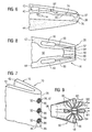
- FIG. 3 shows the perspective view of the trailing edge 20 of the airfoil 16 while blanking the outer and inner platform.
- the cavity 38 arranged inside the turbine blade 10, as part of the first channel system 30, merges into the first connection passage 46, which in turn merges into the first outlet opening 48, which is arranged in the trailing edge 22 of the turbine blade 10.
- second channels 40 are provided, which extend over the height of the blade 16.
- the second channels 40 are connected via second connecting passages 50 to the second outlet openings 52.
- mixer assemblies 70 for better mixing of the two outflowing media M1, M2.
- the mixing internals 70 are pyramid-shaped, designed as wedges or as tetrahedron 72, in whose rear, ie downstream, triangular surface in each case the second outlet opening 52 is provided.
- two tetrahedrons 72a, 72c are provided on the inner side 74 of the suction-side blade wall 42, the free tips of which face the inner side 76 of the pressure-side blade wall 44.
- the first medium M1 preferably cooling air, in a known manner, for example meandering, flowable, in the meantime to protect the material forming the blade 16 from thermal overloading. From there, it passes via the first connecting passages 46 to the first outlet opening 48.
- the second medium M2, preferably fuel, supplied to the second channels 40 is guided to the second outlet openings 52.
- FIG. 4 shows the cross section through the configuration of a turbine blade according to FIG. 3 in which the mutually offset tetrahedron 72, the suction-side blade wall 42, the pressure-side blade wall 44, the two first channels 30 and the two second channels 40 are shown.
- the tetrahedron 72 instead of the tetrahedron 72, other geometric shapes than mixer assemblies 70 are conceivable.
- FIG. 5 An alternative embodiment of the invention shows FIG. 5 in that the cavity 38 provided inside the turbine blade 10 for guiding cooling air is provided as the first medium M1.
- the second channel 40 is provided for guiding the second medium M2.
- At the trailing edge 20 are distributed over the height of the turbine blade 10 each outlet openings 48, 52 provided in pairs.
- Each first and each second outlet opening 48, 52 is connected in each case via its associated helical connection passage 50, 46 with the associated channel system 30, 40. In this case, two connection channels 46, 50 are always entwined in the manner of a double helix.
- the media M1, M2 flowing through the helically winding connecting passages 46, 50 also continue to flow after leaving the turbine blade 10 with the swirl imposed thereby.
- the connecting passages 46, 50 are aligned with one another such that after the exit of the two media M1, M2 from the outlet openings 48, 52 they flow into one another and thus bring about particularly efficient mixing within a particularly short mixing section and mixing time.
- This particularly efficient mixing is a prerequisite for the low-emission burning of the mixture with a short burn-out time after autoignition due to the temperature prevailing in the working gas 22 temperature.
- the working gas 22 or the cooling air flowing into the turbine is reheated, as a result of which its energy content can be increased and utilized as mechanical energy provided by the turbine. Furthermore, this increases the efficiency of the turbine.
- FIG. 6 shows a cross section through the trailing edge 20 of a modified turbine blade 10.
- the means of producing a particularly efficient mixing is one-sided
- the sheet metal element 80 is attached either to the inside 76 of the pressure-side paddle wall 44 or to the inside 74 of the suction-side wall 42, for example by welding or soldering, and vibrates during operation on the basis of FIG media M1, M2 flowing therealong between the two opposite inner sides 74, 76 of the pressure-side blade wall 44 and the suction-side blade wall 42 periodically back and forth, so that the outlet openings 48 and 52 mutually larger and smaller.
- the outflowing media M1, M2 swirl, so that downstream of the sheet metal element 80 a particularly efficient mixing of the two media M1, M2 takes place while achieving the aforementioned advantages.
- the free end 82 of the sheet metal part 80 is slightly thickened in cross section, so that it has an increased mass at this point. On the one hand, this facilitates the maintenance of the oscillation of the sheet metal element 80 and, on the other hand, serves to facilitate the generation of vertebrae, for example for producing Kármán vertebrae. It is not necessary that the free end 82 of the sheet metal element 80 comes to rest on the inner sides 74, 76 of the blade walls 42, 44 during the vibration process.
- FIG. 6 Another advantage of in FIG. 6 As shown, when the medium M2 is suppressed, the channel system 40 is separable from the working gas space 24, since the pressure prevailing in the working gas 22 or in the medium M1 presses the sheet metal element 80 against the inside 74 of the suction side vane wall 42. The otherwise caused by the medium M2 back pressure is missing in this case. The outlet opening 52 is then closed and thus protected against prestigegaseinzug.
- FIG. 9 show in different views, the trailing edge 20 of the turbine blade 10 with nozzle-shaped outlet openings 48, 52.
- the insert 90 has, as in FIG. 9 represented on the outflow side - with respect to the flow direction of the two media M1, M2 - a circumferential contour 96 in the manner of a star.
- a substantially simpler contour 98 for example that of a rectangle, is provided.
- the area enclosed by the star-shaped circumferential contour 96 of the insert 90 forms the first outlet opening 48.
- the area lying between the circular contour 93 of the opening 92 and the area outside the star-shaped contour 96 then forms the second outlet opening 52.
- the turbine blade 10 in the region of the trailing edge 20 according to FIG. 8 with two respectively provided in the blade walls 42, 44 second channels 40 and with the introduced in the trailing edge opening 92 can with a according to FIG. 9 configured and inserted into the opening 92 insert 90 a particularly simple turbulence of the two flowing out of the trailing edge 20 of the turbine blade 10 media M1, M2 can be achieved.
- the first medium M1 preferably cooling air, and is guided due to the changing along the flow direction contour of the insert 90 according to this.
- the outflow-side contour 96 of the insert 90 with fingers 94 protruding in a star shape causes the medium M2, which is supplied from the second connection passages 50, to flow into the intermediate spaces 99 lying between the fingers 94.
- This design also referred to as a flower mixer, also has extremely intensive mixing rates.
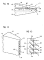
- FIG. 10 to FIG. 12 show a further embodiment of the invention, in which in the region of the trailing edge 20 over the height H a wave-like insert 100 for generating turbulence in the outflowing media M1, M2 is provided.
- the trailing edge 20 has a rectangular slot 102 extending over its height H, which is bisected by an insert 100 inserted therein over its height.
- the insert 100 is spaced from the two inner sides 74, 76 of the blade walls 42, 44, with the spacing between each inner wall 74, 76 and insert 10 periodically increasing and decreasing due to the waveform of the insert 100 as seen along the trailing edge 20.
- the wavefront 104 of the insert 100 which is provided as means for generating swirls, is inclined with respect to the flow direction of the media M1, M2, so that the media M1, M2 guided on both sides of the insert 100 flow across the swirls of the insert 100 and are swirled by them; so that a homogeneous mixing of the two media M1, M2 takes place downstream of the insert 100.
- the resulting mixture heats working gas 22 after or can also serve for the emission treatment of the working gas 22.
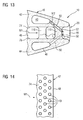
- FIG. 13 and FIG. 14 10 show an alternative embodiment in which only the first medium M1 guided through the first connection passages 46 form a series of vortex streets due to staggered pins 110 which extend from the inside 76 of the pressure-side blade wall 44 to the inside 74 of the suction-side blade wall 42 is swirled.
- the blowing out of the second medium M2 from the turbine blade 10 into the swirling first medium M1 is effected by second outlet openings 52 provided at the trailing edge 20 whose upstream second connecting passages 50 are rectilinear but inclined towards the outer or inner platform.
- the means for generating turbulence in the medium M1 is the field of pins 110 provided in the first connection passage 46.
- the pins 110 may be provided on the inner sides 74, 76 and dimples, turbulators or grooves.
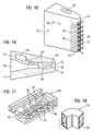
- a further embodiment of the invention is in the FIG. 15 to FIG. 17 4, in which a substantially solid and in its dimensions rectangular insert 120 is inserted into a slot 122 provided in the trailing edge 20 of the turbine blade 10, with which the turbulence of the two media M1, M2 flowing out at this point is brought about.
- the in FIG. 17 insert 120 shown in perspective is equipped with a plurality of mutually parallel first connecting passages 46, which extend transversely to the second connecting passages 50.
- First and second communication passages 46, 50 intersect each other without being connected to each other at the intersections and open into pairs coincident outlets 48, 52, where the mixing of the two media M1, M2 takes place. Due to the obliquely lying outflow directions of the two media M1, M2 they are efficiently swirled and mixed with each other within a short mixing section.
- Parallel to the outwardly and inwardly inclined to the platforms connecting passages 46, 50 may be provided on the working gas 22 facing surface of the blade walls 42, 44, preferably in the region of the trailing edge 20 as well as swirling elements in the form of grooves or dimples that the working gas 22 additionally swirl.
- FIG. 18 shows a perspective view of a tubular, rectangular in flow cross-section insert 130, which has means for the production of kidney vertebrae 132 inside.
- the introduced into the kidney fluid stream other medium is mixed particularly evenly with the one medium due to the turbulence.
- a turbine equipped with such a turbine blade is particularly suitable for manipulating the working medium flowing into it by supplying additional media.
- the energy content of the working medium can be increased by "in-situ blade reheat" or the emission load of the working medium can be lowered by the addition of additives.
- the invention proposes a trailing edge of a turbine blade, by means of which two media guided inside the turbine blade are added to the working gas in such a way that they first mix with one another before the mixture or one of the media reacts only partially with the working gas.
- means for swirling or twisting of the flows are provided, whereby, in the case of a combustible mixture, a particularly low-emission combustion of the mixture for reheating the working gas due to a particularly short mixing section and a short Mixing time in time, even before leaving the turbine, can be achieved.
Landscapes
- Engineering & Computer Science (AREA)
- Mechanical Engineering (AREA)
- General Engineering & Computer Science (AREA)
- Chemical & Material Sciences (AREA)
- Combustion & Propulsion (AREA)
- Physics & Mathematics (AREA)
- Fluid Mechanics (AREA)
- Turbine Rotor Nozzle Sealing (AREA)
Claims (14)
- Aube ( 10 ) de turbine,
comprenant une lame ( 16 ) d'aube profilée et sur laquelle peut passer un gaz ( 22 ) de travail,
qui a un bord ( 18 ) avant auquel peut arriver du gaz ( 22 ) de travail ainsi qu'
un bord ( 20 ) arrière s'étendant le long d'un axe ( 21 ) principal de lame d'aube d'une partie ( 13 ) de pied de la lame ( 16 ) d'aube à une partie ( 15 ) de tête qui lui est opposée, où le gaz ( 22 ) de travail peut partir, et
comprenant un premier système ( 30 ) de canalisation et un deuxième système ( 40 ) de canalisation pour la conduite séparée de deux fluides ( M1, M2 ) différents pouvant être amenés de manière séparée à l'aube ( 10 ) de turbine, dont l'un est un combustible,
dans laquelle le premier système ( 30 ) de canalisation débouche dans au moins une première ouverture ( 48 ) de sortie disposée dans la zone du bord ( 20 ) arrière pour l'insufflation du premier fluide ( M1 ) dans le gaz ( 22 ) de travail, et
dans laquelle au moins une deuxième ouverture ( 52 ) de sortie, disposée dans la zone du bord ( 20 ) arrière pour l'insufflation du deuxième fluide ( M2 ), communique avec le deuxième système ( 40 ) de canalisation,
caractérisée en ce que
considéré le long de l'axe ( 21 ) principal de la lame d'aube, la deuxième ouverture ( 52 ) de sortie est disposée au moins en partie au même niveau que la première ouverture ( 48 ) de sortie. - Aube ( 10 ) de turbine suivant la revendication 1,
dans laquelle respectivement l'une des premières ouvertures ( 48 ) de sortie forme, avec respectivement l'une des deuxièmes ouvertures ( 52 ) de sortie, une paire d'ouvertures se chevauchant considéré le long de l'axe ( 21 ) principal de la lame d'aube. - Aube ( 10 ) de turbine suivant la revendication 1 ou 2, ayant une pluralité de premières ouvertures ( 48 ) de sortie et/ou une pluralité de deuxièmes ouvertures ( 52 ) de sortie.
- Aube ( 10 ) de turbine suivant l'une des revendications 2 ou 3,
dans laquelle des paires d'ouvertures se succèdent le long du bord ( 20 ) arrière. - Aube ( 10 ) de turbine suivant l'une des revendications 1 à 4,
dans laquelle il est prévu dans la zone du bord ( 20 ) arrière un moyen qui provoque un mélange du premier fluide ( M1 ) au deuxième fluide ( M2 ) juste en aval des ouvertures ( 48, 52 ) de sortie. - Aube ( 10 ) de turbine suivant la revendication 5,
dans laquelle le moyen provoque un mélange sans reflux du premier fluide ( M1 ) au deuxième fluide ( M2 ) par le fait que l'un des deux fluides ( M1, M2 ) ou que les deux fluides ( M1, M2 ) peut être insufflé dans le gaz ( 22 ) de travail dans la zone d'un bord vif. - Aube ( 10 ) de turbine suivant la revendication 5 ou 6, dans laquelle le moyen comprend des passages ( 46, 50 ) de communication disposés dans le bord ( 20 ) arrière de la lame ( 16 ) d'aube,
qui mettent au moins l'une des deux canalisations ( 30, 40 ) en communication avec les ouvertures ( 48, 52 ) de sortie qui lui ou leur sont associées,
dans laquelle les passages ( 46, 50 ) de communication sont conformés, de manière à imprimer une torsion ou un tourbillonnement aux fluides ( M1, M2 ) qui y passent. - Aube ( 10 ) de turbine suivant la revendication 6,
dans laquelle le moyen est prévu dans les ouvertures ( 48, 52 ) de sortie. - Aube ( 10 ) de turbine suivant la revendication 5 ou 6,
dans laquelle le moyen est prévu pour mélanger le premier fluide ( M1 ) au deuxième fluide ( M2 ) sur une face intérieure de la paroi ( 42 ) d'extrados et/ou sur une face intérieure de la paroi ( 44 ) d'intrados de la lame ( 16 ) d'aube. - Aube ( 10 ) de turbine suivant la revendication 9,
dans laquelle il est prévu comme moyen des inserts formant mélangeur en forme de tétraèdre, des bossages des agents de turbulence ou des champs de broches dans l'une des ouvertures ( 48, 52 ) de sortie ou en amont de celle ci. - Aube ( 10 ) de turbine suivant l'une des revendications 1 à 10,
dans laquelle il est prévu des éléments de turbulence du côté du gaz chaud sur la lame ( 16 ) d'aube, sur laquelle passe le gaz ( 22 ) de travail. - Aube ( 10 ) de turbine en plusieurs parties suivant l'une des revendications 5 à 11,
dans laquelle la lame ( 16 ) d'aube est coulée et le moyen de mélange des deux fluides ( M1, M2 ) est fixé à la lame ( 16 ) d'aube sous la forme d'inserts ( 90, 100, 110, 120 ) fabriqués séparément. - Aube ( 10 ) de turbine suivant la revendication 12,
dans laquelle l'insert ( 90, 100, 110, 120 ) est de type en tôle ondulée ou en forme de buse et est utilisé pour la formation des ouvertures ( 48, 52 ) de sortie dans un trou ( 90 ) ou dans une fente ( 102, 122 ). - Turbine à gaz ayant une aube ( 16 ) de turbine suivant l'une des revendications précédentes.
Priority Applications (2)
| Application Number | Priority Date | Filing Date | Title |
|---|---|---|---|
| PL07726359T PL2010757T3 (pl) | 2006-04-21 | 2007-02-13 | Łopatka turbiny |
| EP07726359.8A EP2010757B1 (fr) | 2006-04-21 | 2007-02-13 | Aube de turbine |
Applications Claiming Priority (3)
| Application Number | Priority Date | Filing Date | Title |
|---|---|---|---|
| EP06008319A EP1847684A1 (fr) | 2006-04-21 | 2006-04-21 | Aube de turbine |
| PCT/EP2007/051403 WO2007122022A1 (fr) | 2006-04-21 | 2007-02-13 | Aube de turbine |
| EP07726359.8A EP2010757B1 (fr) | 2006-04-21 | 2007-02-13 | Aube de turbine |
Publications (2)
| Publication Number | Publication Date |
|---|---|
| EP2010757A1 EP2010757A1 (fr) | 2009-01-07 |
| EP2010757B1 true EP2010757B1 (fr) | 2013-06-19 |
Family
ID=37395964
Family Applications (2)
| Application Number | Title | Priority Date | Filing Date |
|---|---|---|---|
| EP06008319A Withdrawn EP1847684A1 (fr) | 2006-04-21 | 2006-04-21 | Aube de turbine |
| EP07726359.8A Not-in-force EP2010757B1 (fr) | 2006-04-21 | 2007-02-13 | Aube de turbine |
Family Applications Before (1)
| Application Number | Title | Priority Date | Filing Date |
|---|---|---|---|
| EP06008319A Withdrawn EP1847684A1 (fr) | 2006-04-21 | 2006-04-21 | Aube de turbine |
Country Status (7)
| Country | Link |
|---|---|
| US (1) | US8092175B2 (fr) |
| EP (2) | EP1847684A1 (fr) |
| JP (1) | JP5027871B2 (fr) |
| ES (1) | ES2426349T3 (fr) |
| PL (1) | PL2010757T3 (fr) |
| RU (1) | RU2399771C2 (fr) |
| WO (1) | WO2007122022A1 (fr) |
Families Citing this family (65)
| Publication number | Priority date | Publication date | Assignee | Title |
|---|---|---|---|---|
| EP1847696A1 (fr) * | 2006-04-21 | 2007-10-24 | Siemens Aktiengesellschaft | Composant pour un système de post-combustion dans une turbine à gaz et turbine à gaz associée. |
| US10156143B2 (en) * | 2007-12-06 | 2018-12-18 | United Technologies Corporation | Gas turbine engines and related systems involving air-cooled vanes |
| US9163518B2 (en) | 2008-03-18 | 2015-10-20 | United Technologies Corporation | Full coverage trailing edge microcircuit with alternating converging exits |
| US8291705B2 (en) * | 2008-08-13 | 2012-10-23 | General Electric Company | Ultra low injection angle fuel holes in a combustor fuel nozzle |
| EP2163726A1 (fr) * | 2008-09-11 | 2010-03-17 | Siemens Aktiengesellschaft | Aube de turbine dotée d'un rebord arrière modulaire et graduée |
| GB2465337B (en) * | 2008-11-12 | 2012-01-11 | Rolls Royce Plc | A cooling arrangement |
| US8671696B2 (en) * | 2009-07-10 | 2014-03-18 | Leonard M. Andersen | Method and apparatus for increasing thrust or other useful energy output of a device with a rotating element |
| DE102009045950A1 (de) * | 2009-10-23 | 2011-04-28 | Man Diesel & Turbo Se | Drallerzeuger |
| US8608429B2 (en) * | 2010-05-28 | 2013-12-17 | General Electric Company | System and method for enhanced turbine wake mixing via fluidic-generated vortices |
| EP2392775A1 (fr) * | 2010-06-07 | 2011-12-07 | Siemens Aktiengesellschaft | Aude mobile à utiliser dans un écoulement de fluide d'une turbine et turbine correspondant |
| US8608443B2 (en) | 2010-06-11 | 2013-12-17 | Siemens Energy, Inc. | Film cooled component wall in a turbine engine |
| US8984859B2 (en) * | 2010-12-28 | 2015-03-24 | Rolls-Royce North American Technologies, Inc. | Gas turbine engine and reheat system |
| US8764394B2 (en) * | 2011-01-06 | 2014-07-01 | Siemens Energy, Inc. | Component cooling channel |
| US9376933B2 (en) * | 2011-04-29 | 2016-06-28 | Leonard M. Andersen | Apparatus for distributing fluid into a gas turbine |
| US20130195650A1 (en) * | 2012-01-27 | 2013-08-01 | Adebukola O. Benson | Gas Turbine Pattern Swirl Film Cooling |
| US9752441B2 (en) | 2012-01-31 | 2017-09-05 | United Technologies Corporation | Gas turbine rotary blade with tip insert |
| US9011087B2 (en) | 2012-03-26 | 2015-04-21 | United Technologies Corporation | Hybrid airfoil for a gas turbine engine |
| WO2014043567A1 (fr) | 2012-09-14 | 2014-03-20 | Purdue Research Foundation | Canaux entrelacés pour refroidissement interne de surface portante |
| US9404654B2 (en) | 2012-09-26 | 2016-08-02 | United Technologies Corporation | Gas turbine engine combustor with integrated combustor vane |
| US9482432B2 (en) | 2012-09-26 | 2016-11-01 | United Technologies Corporation | Gas turbine engine combustor with integrated combustor vane having swirler |
| US9995150B2 (en) | 2012-10-23 | 2018-06-12 | Siemens Aktiengesellschaft | Cooling configuration for a gas turbine engine airfoil |
| US8936067B2 (en) | 2012-10-23 | 2015-01-20 | Siemens Aktiengesellschaft | Casting core for a cooling arrangement for a gas turbine component |
| US8951004B2 (en) | 2012-10-23 | 2015-02-10 | Siemens Aktiengesellschaft | Cooling arrangement for a gas turbine component |
| US9394797B2 (en) | 2012-12-04 | 2016-07-19 | General Electric Company | Turbomachine nozzle having fluid conduit and related turbomachine |
| US9790801B2 (en) * | 2012-12-27 | 2017-10-17 | United Technologies Corporation | Gas turbine engine component having suction side cutback opening |
| US9458767B2 (en) | 2013-03-18 | 2016-10-04 | General Electric Company | Fuel injection insert for a turbine nozzle segment |
| US8985949B2 (en) * | 2013-04-29 | 2015-03-24 | Siemens Aktiengesellschaft | Cooling system including wavy cooling chamber in a trailing edge portion of an airfoil assembly |
| EP3008290B1 (fr) * | 2013-06-14 | 2018-10-31 | United Technologies Corporation | Aube de turbine à rayon interne de bord de fuite variable |
| JP6245740B2 (ja) * | 2013-11-20 | 2017-12-13 | 三菱日立パワーシステムズ株式会社 | ガスタービン翼 |
| US9810072B2 (en) * | 2014-05-28 | 2017-11-07 | General Electric Company | Rotor blade cooling |
| US10145246B2 (en) | 2014-09-04 | 2018-12-04 | United Technologies Corporation | Staggered crossovers for airfoils |
| US10094570B2 (en) | 2014-12-11 | 2018-10-09 | General Electric Company | Injector apparatus and reheat combustor |
| US10094571B2 (en) | 2014-12-11 | 2018-10-09 | General Electric Company | Injector apparatus with reheat combustor and turbomachine |
| US10094569B2 (en) | 2014-12-11 | 2018-10-09 | General Electric Company | Injecting apparatus with reheat combustor and turbomachine |
| US10107498B2 (en) * | 2014-12-11 | 2018-10-23 | General Electric Company | Injection systems for fuel and gas |
| US10323524B2 (en) * | 2015-05-08 | 2019-06-18 | United Technologies Corporation | Axial skin core cooling passage for a turbine engine component |
| US10502066B2 (en) | 2015-05-08 | 2019-12-10 | United Technologies Corporation | Turbine engine component including an axially aligned skin core passage interrupted by a pedestal |
| FR3038343B1 (fr) * | 2015-07-02 | 2017-07-21 | Snecma | Aube de turbine a bord de fuite ameliore |
| FR3039228B1 (fr) * | 2015-07-22 | 2020-01-03 | Safran Aircraft Engines | Aeronef comprenant un propulseur arriere carene avec stator d'entree comprenant une fonction soufflage |
| DE102015215144B4 (de) | 2015-08-07 | 2017-11-09 | MTU Aero Engines AG | Vorrichtung und Verfahren zum Beeinflussen der Temperaturen in Innenringsegmenten einer Gasturbine |
| US10370978B2 (en) | 2015-10-15 | 2019-08-06 | General Electric Company | Turbine blade |
| US10174620B2 (en) | 2015-10-15 | 2019-01-08 | General Electric Company | Turbine blade |
| US10208605B2 (en) | 2015-10-15 | 2019-02-19 | General Electric Company | Turbine blade |
| US10443398B2 (en) | 2015-10-15 | 2019-10-15 | General Electric Company | Turbine blade |
| US10370979B2 (en) * | 2015-11-23 | 2019-08-06 | United Technologies Corporation | Baffle for a component of a gas turbine engine |
| US20170176012A1 (en) * | 2015-12-22 | 2017-06-22 | General Electric Company | Fuel injectors and staged fuel injection systems in gas turbines |
| US10337341B2 (en) | 2016-08-01 | 2019-07-02 | United Technologies Corporation | Additively manufactured augmentor vane of a gas turbine engine with additively manufactured fuel line extending therethrough |
| US10436447B2 (en) * | 2016-08-01 | 2019-10-08 | United Technologies Corporation | Augmentor vane assembly of a gas turbine engine with an additively manufactured augmentor vane |
| US10598025B2 (en) * | 2016-11-17 | 2020-03-24 | United Technologies Corporation | Airfoil with rods adjacent a core structure |
| US10619499B2 (en) * | 2017-01-23 | 2020-04-14 | General Electric Company | Component and method for forming a component |
| US10583489B2 (en) * | 2017-04-26 | 2020-03-10 | General Electric Company | Method of providing cooling structure for a component |
| DE102017207487A1 (de) * | 2017-05-04 | 2018-11-08 | Siemens Aktiengesellschaft | Brennkammer |
| US10570751B2 (en) | 2017-11-22 | 2020-02-25 | General Electric Company | Turbine engine airfoil assembly |
| US11346246B2 (en) * | 2017-12-01 | 2022-05-31 | Siemens Energy, Inc. | Brazed in heat transfer feature for cooled turbine components |
| KR102048863B1 (ko) * | 2018-04-17 | 2019-11-26 | 두산중공업 주식회사 | 인서트 지지부를 구비한 터빈 베인 |
| US10753210B2 (en) * | 2018-05-02 | 2020-08-25 | Raytheon Technologies Corporation | Airfoil having improved cooling scheme |
| US11753944B2 (en) | 2018-11-09 | 2023-09-12 | Raytheon Technologies Corporation | Airfoil with wall that tapers in thickness |
| US11078844B2 (en) * | 2018-11-21 | 2021-08-03 | Raytheon Technologies Corporation | Thermal gradient reducing device for gas turbine engine component |
| FR3099522B1 (fr) * | 2019-07-30 | 2021-08-20 | Safran Aircraft Engines | Aube mobile de turbomachine à circuit de refroidissement ayant une double rangée de fentes d’évacuation |
| US11732594B2 (en) * | 2019-11-27 | 2023-08-22 | General Electric Company | Cooling assembly for a turbine assembly |
| US11814965B2 (en) | 2021-11-10 | 2023-11-14 | General Electric Company | Turbomachine blade trailing edge cooling circuit with turn passage having set of obstructions |
| CN115247575B (zh) * | 2022-05-12 | 2024-05-03 | 中国航发四川燃气涡轮研究院 | 一种螺旋状涡轮叶片冷却单元及冷却结构 |
| US20250283417A1 (en) * | 2023-08-09 | 2025-09-11 | Ge Infrastructure Technology Llc | Trailing edge cooling circuit for turbomachine airfoil |
| US12286899B2 (en) * | 2023-08-09 | 2025-04-29 | Ge Infrastructure Technology Llc | Trailing edge cooling circuit |
| KR20260038676A (ko) * | 2024-09-12 | 2026-03-19 | 두산에너빌리티 주식회사 | 냉각 세그먼트 및 이를 포함하는 가스터빈 |
Family Cites Families (25)
| Publication number | Priority date | Publication date | Assignee | Title |
|---|---|---|---|---|
| US3191908A (en) * | 1961-05-02 | 1965-06-29 | Rolls Royce | Blades for fluid flow machines |
| US3527543A (en) * | 1965-08-26 | 1970-09-08 | Gen Electric | Cooling of structural members particularly for gas turbine engines |
| US3574481A (en) * | 1968-05-09 | 1971-04-13 | James A Pyne Jr | Variable area cooled airfoil construction for gas turbines |
| GB1361256A (en) * | 1971-08-25 | 1974-07-24 | Rolls Royce | Gas turbine engine blades |
| US3934322A (en) * | 1972-09-21 | 1976-01-27 | General Electric Company | Method for forming cooling slot in airfoil blades |
| US4080095A (en) * | 1976-09-02 | 1978-03-21 | Westinghouse Electric Corporation | Cooled turbine vane |
| US4297077A (en) * | 1979-07-09 | 1981-10-27 | Westinghouse Electric Corp. | Cooled turbine vane |
| GB2163219B (en) * | 1981-10-31 | 1986-08-13 | Rolls Royce | Cooled turbine blade |
| SU1238465A2 (ru) * | 1983-08-05 | 1996-02-27 | Уфимский авиационный институт им.Серго Орджоникидзе | Охлаждаемая лопатка турбины |
| SU1332933A2 (ru) * | 1985-04-29 | 2005-12-10 | К.С. Нетесов | Рабочая лопатка газовой турбины |
| SU1489248A2 (ru) * | 1987-10-30 | 2005-12-10 | Г.П. Нагога | Рабочая лопатка газовой турбины |
| US5690472A (en) * | 1992-02-03 | 1997-11-25 | General Electric Company | Internal cooling of turbine airfoil wall using mesh cooling hole arrangement |
| US5931638A (en) * | 1997-08-07 | 1999-08-03 | United Technologies Corporation | Turbomachinery airfoil with optimized heat transfer |
| DE59907940D1 (de) | 1998-03-10 | 2004-01-15 | Siemens Ag | Brennkammer und verfahren zum betrieb einer brennkammer |
| DE59910200D1 (de) * | 1999-04-21 | 2004-09-16 | Alstom Technology Ltd Baden | Kühlbares Bauteil |
| US6298667B1 (en) * | 2000-06-22 | 2001-10-09 | General Electric Company | Modular combustor dome |
| US6551063B1 (en) * | 2001-12-20 | 2003-04-22 | General Electric Company | Foil formed structure for turbine airfoil trailing edge |
| US7014424B2 (en) * | 2003-04-08 | 2006-03-21 | United Technologies Corporation | Turbine element |
| PL1651841T3 (pl) | 2003-07-04 | 2008-01-31 | Siemens Ag | Chłodzony w systemie otwartym element dla turbiny gazowej, komora spalania i turbina gazowa |
| DE502004002003D1 (de) * | 2004-03-25 | 2006-12-28 | Rolls Royce Deutschland | Verdichter für ein Flugzeugtriebwerk |
| GB2428749B (en) * | 2005-08-02 | 2007-11-28 | Rolls Royce Plc | A component comprising a multiplicity of cooling passages |
| US7296973B2 (en) * | 2005-12-05 | 2007-11-20 | General Electric Company | Parallel serpentine cooled blade |
| US7563072B1 (en) * | 2006-09-25 | 2009-07-21 | Florida Turbine Technologies, Inc. | Turbine airfoil with near-wall spiral flow cooling circuit |
| US7731481B2 (en) * | 2006-12-18 | 2010-06-08 | United Technologies Corporation | Airfoil cooling with staggered refractory metal core microcircuits |
| US7753650B1 (en) * | 2006-12-20 | 2010-07-13 | Florida Turbine Technologies, Inc. | Thin turbine rotor blade with sinusoidal flow cooling channels |
-
2006
- 2006-04-21 EP EP06008319A patent/EP1847684A1/fr not_active Withdrawn
-
2007
- 2007-02-13 PL PL07726359T patent/PL2010757T3/pl unknown
- 2007-02-13 ES ES07726359T patent/ES2426349T3/es active Active
- 2007-02-13 WO PCT/EP2007/051403 patent/WO2007122022A1/fr not_active Ceased
- 2007-02-13 RU RU2008145903/06A patent/RU2399771C2/ru not_active IP Right Cessation
- 2007-02-13 JP JP2009505808A patent/JP5027871B2/ja not_active Expired - Fee Related
- 2007-02-13 EP EP07726359.8A patent/EP2010757B1/fr not_active Not-in-force
- 2007-02-13 US US12/226,537 patent/US8092175B2/en not_active Expired - Fee Related
Also Published As
| Publication number | Publication date |
|---|---|
| ES2426349T3 (es) | 2013-10-22 |
| RU2008145903A (ru) | 2010-05-27 |
| EP1847684A1 (fr) | 2007-10-24 |
| EP2010757A1 (fr) | 2009-01-07 |
| US8092175B2 (en) | 2012-01-10 |
| JP5027871B2 (ja) | 2012-09-19 |
| PL2010757T3 (pl) | 2013-11-29 |
| US20090185903A1 (en) | 2009-07-23 |
| WO2007122022A1 (fr) | 2007-11-01 |
| RU2399771C2 (ru) | 2010-09-20 |
| JP2009534570A (ja) | 2009-09-24 |
Similar Documents
| Publication | Publication Date | Title |
|---|---|---|
| EP2010757B1 (fr) | Aube de turbine | |
| DE19533055B4 (de) | Doppelbrennstoffmischer für eine Gasturbinenbrennkammer | |
| EP3087323B1 (fr) | Injecteur de combustible, brûleur avec un tel injecteur de combustible, et turbine à gaz munie dudit brûleur | |
| DE102005024062B4 (de) | Brennerrohr und Verfahren zum Mischen von Luft und Gas in einem Gasturbinentriebwerk | |
| DE102007004394B4 (de) | Brenner zum Verbrennen eines Vorgemischs für eine Gasturbine | |
| DE2338673C2 (de) | Nachbrenneranordnung für ein Gasturbinenstrahltriebwerk | |
| DE4426351B4 (de) | Brennkammer für eine Gasturbine | |
| DE112004002704B4 (de) | Verbrennungsanlage | |
| DE2143012C3 (de) | Brenneranordnung bei einer Gasturbinen-Brennkammer | |
| DE60310170T2 (de) | Brennstoffinjektionsvorrichtung | |
| DE69617290T2 (de) | Verbrennungsgerät für Gasturbinenmotor | |
| DE69312362T2 (de) | Brennkammer mit Verdünnungsleitschaufeln | |
| EP2233836B1 (fr) | Générateur de torsion, procédé destiné à empêcher des retours de flammes dans un brûleur, doté d'au moins un générateur de torsion et d'un brûleur | |
| DE69919764T2 (de) | Brennkammer | |
| EP2156095B1 (fr) | Stabilisation sans tourbillonner de la flamme d'un brûleur à prémélange | |
| DE102010036488B4 (de) | Gasturbinenbrenner | |
| DE112014004695B4 (de) | Brennstoffeinspritzvorrichtung für eine Gasturbine | |
| DE19510744A1 (de) | Brennkammer mit Zweistufenverbrennung | |
| CH699760A2 (de) | Brennstoffdüse mit einem Brennstoff-Luft-Vormischer für eine Gasturbinenbrennkammer. | |
| EP2423597B1 (fr) | Brûleur à prémélange pour une turbine à gaz | |
| DE3821078A1 (de) | Ringvergasungsbrenner fuer gasturbine | |
| EP2307806B1 (fr) | Agencement de brûleur pour combustibles liquides et procédé de fabrication d'un agencement de brûleur | |
| EP0718561A2 (fr) | Brûleur | |
| DE4446611A1 (de) | Brennkammer | |
| CH707760A2 (de) | Gasturbine mit einer stromabwärtigen Brennstoff- und Luftinjektion. |
Legal Events
| Date | Code | Title | Description |
|---|---|---|---|
| PUAI | Public reference made under article 153(3) epc to a published international application that has entered the european phase |
Free format text: ORIGINAL CODE: 0009012 |
|
| 17P | Request for examination filed |
Effective date: 20080919 |
|
| AK | Designated contracting states |
Kind code of ref document: A1 Designated state(s): AT BE BG CH CY CZ DE DK EE ES FI FR GB GR HU IE IS IT LI LT LU LV MC NL PL PT RO SE SI SK TR |
|
| AX | Request for extension of the european patent |
Extension state: AL BA HR MK RS |
|
| DAX | Request for extension of the european patent (deleted) | ||
| GRAP | Despatch of communication of intention to grant a patent |
Free format text: ORIGINAL CODE: EPIDOSNIGR1 |
|
| RAP1 | Party data changed (applicant data changed or rights of an application transferred) |
Owner name: SIEMENS AKTIENGESELLSCHAFT |
|
| GRAS | Grant fee paid |
Free format text: ORIGINAL CODE: EPIDOSNIGR3 |
|
| GRAA | (expected) grant |
Free format text: ORIGINAL CODE: 0009210 |
|
| AK | Designated contracting states |
Kind code of ref document: B1 Designated state(s): AT BE BG CH CY CZ DE DK EE ES FI FR GB GR HU IE IS IT LI LT LU LV MC NL PL PT RO SE SI SK TR |
|
| REG | Reference to a national code |
Ref country code: GB Ref legal event code: FG4D Free format text: NOT ENGLISH |
|
| REG | Reference to a national code |
Ref country code: CH Ref legal event code: EP |
|
| REG | Reference to a national code |
Ref country code: AT Ref legal event code: REF Ref document number: 617769 Country of ref document: AT Kind code of ref document: T Effective date: 20130715 |
|
| REG | Reference to a national code |
Ref country code: IE Ref legal event code: FG4D Free format text: LANGUAGE OF EP DOCUMENT: GERMAN Ref country code: CH Ref legal event code: NV Representative=s name: SIEMENS SCHWEIZ AG, CH |
|
| REG | Reference to a national code |
Ref country code: DE Ref legal event code: R096 Ref document number: 502007011921 Country of ref document: DE Effective date: 20130814 |
|
| REG | Reference to a national code |
Ref country code: ES Ref legal event code: FG2A Ref document number: 2426349 Country of ref document: ES Kind code of ref document: T3 Effective date: 20131022 |
|
| REG | Reference to a national code |
Ref country code: NL Ref legal event code: T3 |
|
| PG25 | Lapsed in a contracting state [announced via postgrant information from national office to epo] |
Ref country code: LT Free format text: LAPSE BECAUSE OF FAILURE TO SUBMIT A TRANSLATION OF THE DESCRIPTION OR TO PAY THE FEE WITHIN THE PRESCRIBED TIME-LIMIT Effective date: 20130619 Ref country code: SE Free format text: LAPSE BECAUSE OF FAILURE TO SUBMIT A TRANSLATION OF THE DESCRIPTION OR TO PAY THE FEE WITHIN THE PRESCRIBED TIME-LIMIT Effective date: 20130619 Ref country code: SI Free format text: LAPSE BECAUSE OF FAILURE TO SUBMIT A TRANSLATION OF THE DESCRIPTION OR TO PAY THE FEE WITHIN THE PRESCRIBED TIME-LIMIT Effective date: 20130619 Ref country code: FI Free format text: LAPSE BECAUSE OF FAILURE TO SUBMIT A TRANSLATION OF THE DESCRIPTION OR TO PAY THE FEE WITHIN THE PRESCRIBED TIME-LIMIT Effective date: 20130619 Ref country code: GR Free format text: LAPSE BECAUSE OF FAILURE TO SUBMIT A TRANSLATION OF THE DESCRIPTION OR TO PAY THE FEE WITHIN THE PRESCRIBED TIME-LIMIT Effective date: 20130920 |
|
| REG | Reference to a national code |
Ref country code: LT Ref legal event code: MG4D |
|
| PG25 | Lapsed in a contracting state [announced via postgrant information from national office to epo] |
Ref country code: BG Free format text: LAPSE BECAUSE OF FAILURE TO SUBMIT A TRANSLATION OF THE DESCRIPTION OR TO PAY THE FEE WITHIN THE PRESCRIBED TIME-LIMIT Effective date: 20130919 |
|
| REG | Reference to a national code |
Ref country code: PL Ref legal event code: T3 |
|
| PG25 | Lapsed in a contracting state [announced via postgrant information from national office to epo] |
Ref country code: LV Free format text: LAPSE BECAUSE OF FAILURE TO SUBMIT A TRANSLATION OF THE DESCRIPTION OR TO PAY THE FEE WITHIN THE PRESCRIBED TIME-LIMIT Effective date: 20130619 |
|
| PG25 | Lapsed in a contracting state [announced via postgrant information from national office to epo] |
Ref country code: EE Free format text: LAPSE BECAUSE OF FAILURE TO SUBMIT A TRANSLATION OF THE DESCRIPTION OR TO PAY THE FEE WITHIN THE PRESCRIBED TIME-LIMIT Effective date: 20130619 Ref country code: CZ Free format text: LAPSE BECAUSE OF FAILURE TO SUBMIT A TRANSLATION OF THE DESCRIPTION OR TO PAY THE FEE WITHIN THE PRESCRIBED TIME-LIMIT Effective date: 20130619 Ref country code: SK Free format text: LAPSE BECAUSE OF FAILURE TO SUBMIT A TRANSLATION OF THE DESCRIPTION OR TO PAY THE FEE WITHIN THE PRESCRIBED TIME-LIMIT Effective date: 20130619 Ref country code: PT Free format text: LAPSE BECAUSE OF FAILURE TO SUBMIT A TRANSLATION OF THE DESCRIPTION OR TO PAY THE FEE WITHIN THE PRESCRIBED TIME-LIMIT Effective date: 20131021 Ref country code: IS Free format text: LAPSE BECAUSE OF FAILURE TO SUBMIT A TRANSLATION OF THE DESCRIPTION OR TO PAY THE FEE WITHIN THE PRESCRIBED TIME-LIMIT Effective date: 20131019 Ref country code: CY Free format text: LAPSE BECAUSE OF FAILURE TO SUBMIT A TRANSLATION OF THE DESCRIPTION OR TO PAY THE FEE WITHIN THE PRESCRIBED TIME-LIMIT Effective date: 20130619 |
|
| PG25 | Lapsed in a contracting state [announced via postgrant information from national office to epo] |
Ref country code: RO Free format text: LAPSE BECAUSE OF FAILURE TO SUBMIT A TRANSLATION OF THE DESCRIPTION OR TO PAY THE FEE WITHIN THE PRESCRIBED TIME-LIMIT Effective date: 20130619 |
|
| PLBE | No opposition filed within time limit |
Free format text: ORIGINAL CODE: 0009261 |
|
| STAA | Information on the status of an ep patent application or granted ep patent |
Free format text: STATUS: NO OPPOSITION FILED WITHIN TIME LIMIT |
|
| PG25 | Lapsed in a contracting state [announced via postgrant information from national office to epo] |
Ref country code: DK Free format text: LAPSE BECAUSE OF FAILURE TO SUBMIT A TRANSLATION OF THE DESCRIPTION OR TO PAY THE FEE WITHIN THE PRESCRIBED TIME-LIMIT Effective date: 20130619 |
|
| PGFP | Annual fee paid to national office [announced via postgrant information from national office to epo] |
Ref country code: NL Payment date: 20140204 Year of fee payment: 8 |
|
| 26N | No opposition filed |
Effective date: 20140320 |
|
| PGFP | Annual fee paid to national office [announced via postgrant information from national office to epo] |
Ref country code: PL Payment date: 20140123 Year of fee payment: 8 Ref country code: ES Payment date: 20140305 Year of fee payment: 8 Ref country code: IT Payment date: 20140227 Year of fee payment: 8 Ref country code: FR Payment date: 20140212 Year of fee payment: 8 |
|
| REG | Reference to a national code |
Ref country code: DE Ref legal event code: R097 Ref document number: 502007011921 Country of ref document: DE Effective date: 20140320 |
|
| PGFP | Annual fee paid to national office [announced via postgrant information from national office to epo] |
Ref country code: GB Payment date: 20140210 Year of fee payment: 8 |
|
| BERE | Be: lapsed |
Owner name: SIEMENS A.G. Effective date: 20140228 |
|
| REG | Reference to a national code |
Ref country code: DE Ref legal event code: R119 Ref document number: 502007011921 Country of ref document: DE |
|
| PG25 | Lapsed in a contracting state [announced via postgrant information from national office to epo] |
Ref country code: MC Free format text: LAPSE BECAUSE OF FAILURE TO SUBMIT A TRANSLATION OF THE DESCRIPTION OR TO PAY THE FEE WITHIN THE PRESCRIBED TIME-LIMIT Effective date: 20130619 Ref country code: LU Free format text: LAPSE BECAUSE OF FAILURE TO SUBMIT A TRANSLATION OF THE DESCRIPTION OR TO PAY THE FEE WITHIN THE PRESCRIBED TIME-LIMIT Effective date: 20140213 |
|
| REG | Reference to a national code |
Ref country code: CH Ref legal event code: PL |
|
| PG25 | Lapsed in a contracting state [announced via postgrant information from national office to epo] |
Ref country code: LI Free format text: LAPSE BECAUSE OF NON-PAYMENT OF DUE FEES Effective date: 20140228 Ref country code: CH Free format text: LAPSE BECAUSE OF NON-PAYMENT OF DUE FEES Effective date: 20140228 |
|
| REG | Reference to a national code |
Ref country code: DE Ref legal event code: R119 Ref document number: 502007011921 Country of ref document: DE Effective date: 20140902 |
|
| REG | Reference to a national code |
Ref country code: IE Ref legal event code: MM4A |
|
| PG25 | Lapsed in a contracting state [announced via postgrant information from national office to epo] |
Ref country code: DE Free format text: LAPSE BECAUSE OF NON-PAYMENT OF DUE FEES Effective date: 20140902 Ref country code: IE Free format text: LAPSE BECAUSE OF NON-PAYMENT OF DUE FEES Effective date: 20140213 Ref country code: BE Free format text: LAPSE BECAUSE OF NON-PAYMENT OF DUE FEES Effective date: 20140228 |
|
| REG | Reference to a national code |
Ref country code: AT Ref legal event code: MM01 Ref document number: 617769 Country of ref document: AT Kind code of ref document: T Effective date: 20140213 |
|
| PG25 | Lapsed in a contracting state [announced via postgrant information from national office to epo] |
Ref country code: AT Free format text: LAPSE BECAUSE OF NON-PAYMENT OF DUE FEES Effective date: 20140213 |
|
| REG | Reference to a national code |
Ref country code: NL Ref legal event code: V1 Effective date: 20150901 |
|
| PG25 | Lapsed in a contracting state [announced via postgrant information from national office to epo] |
Ref country code: NL Free format text: LAPSE BECAUSE OF NON-PAYMENT OF DUE FEES Effective date: 20150901 |
|
| GBPC | Gb: european patent ceased through non-payment of renewal fee |
Effective date: 20150213 |
|
| REG | Reference to a national code |
Ref country code: FR Ref legal event code: ST Effective date: 20151030 |
|
| PG25 | Lapsed in a contracting state [announced via postgrant information from national office to epo] |
Ref country code: IT Free format text: LAPSE BECAUSE OF NON-PAYMENT OF DUE FEES Effective date: 20150213 |
|
| PG25 | Lapsed in a contracting state [announced via postgrant information from national office to epo] |
Ref country code: GB Free format text: LAPSE BECAUSE OF NON-PAYMENT OF DUE FEES Effective date: 20150213 |
|
| PG25 | Lapsed in a contracting state [announced via postgrant information from national office to epo] |
Ref country code: FR Free format text: LAPSE BECAUSE OF NON-PAYMENT OF DUE FEES Effective date: 20150302 |
|
| PG25 | Lapsed in a contracting state [announced via postgrant information from national office to epo] |
Ref country code: PL Free format text: LAPSE BECAUSE OF NON-PAYMENT OF DUE FEES Effective date: 20150213 |
|
| PG25 | Lapsed in a contracting state [announced via postgrant information from national office to epo] |
Ref country code: HU Free format text: LAPSE BECAUSE OF FAILURE TO SUBMIT A TRANSLATION OF THE DESCRIPTION OR TO PAY THE FEE WITHIN THE PRESCRIBED TIME-LIMIT; INVALID AB INITIO Effective date: 20070213 Ref country code: TR Free format text: LAPSE BECAUSE OF FAILURE TO SUBMIT A TRANSLATION OF THE DESCRIPTION OR TO PAY THE FEE WITHIN THE PRESCRIBED TIME-LIMIT Effective date: 20130619 |
|
| PG25 | Lapsed in a contracting state [announced via postgrant information from national office to epo] |
Ref country code: ES Free format text: LAPSE BECAUSE OF NON-PAYMENT OF DUE FEES Effective date: 20150214 |
|
| REG | Reference to a national code |
Ref country code: ES Ref legal event code: FD2A Effective date: 20180710 |