EP2010802B1 - Chaine d'acheminement d'energie - Google Patents
Chaine d'acheminement d'energie Download PDFInfo
- Publication number
- EP2010802B1 EP2010802B1 EP07722235.4A EP07722235A EP2010802B1 EP 2010802 B1 EP2010802 B1 EP 2010802B1 EP 07722235 A EP07722235 A EP 07722235A EP 2010802 B1 EP2010802 B1 EP 2010802B1
- Authority
- EP
- European Patent Office
- Prior art keywords
- energy guiding
- rollers
- guiding chain
- tongue
- chain according
- Prior art date
- Legal status (The legal status is an assumption and is not a legal conclusion. Google has not performed a legal analysis and makes no representation as to the accuracy of the status listed.)
- Active
Links
Images

Classifications
-
- F—MECHANICAL ENGINEERING; LIGHTING; HEATING; WEAPONS; BLASTING
- F16—ENGINEERING ELEMENTS AND UNITS; GENERAL MEASURES FOR PRODUCING AND MAINTAINING EFFECTIVE FUNCTIONING OF MACHINES OR INSTALLATIONS; THERMAL INSULATION IN GENERAL
- F16L—PIPES; JOINTS OR FITTINGS FOR PIPES; SUPPORTS FOR PIPES, CABLES OR PROTECTIVE TUBING; MEANS FOR THERMAL INSULATION IN GENERAL
- F16L3/00—Supports for pipes, cables or protective tubing, e.g. hangers, holders, clamps, cleats, clips, brackets
- F16L3/01—Supports for pipes, cables or protective tubing, e.g. hangers, holders, clamps, cleats, clips, brackets for supporting or guiding the pipes, cables or protective tubing, between relatively movable points, e.g. movable channels
- F16L3/015—Supports for pipes, cables or protective tubing, e.g. hangers, holders, clamps, cleats, clips, brackets for supporting or guiding the pipes, cables or protective tubing, between relatively movable points, e.g. movable channels using articulated- or supple-guiding elements
-
- F—MECHANICAL ENGINEERING; LIGHTING; HEATING; WEAPONS; BLASTING
- F16—ENGINEERING ELEMENTS AND UNITS; GENERAL MEASURES FOR PRODUCING AND MAINTAINING EFFECTIVE FUNCTIONING OF MACHINES OR INSTALLATIONS; THERMAL INSULATION IN GENERAL
- F16G—BELTS, CABLES, OR ROPES, PREDOMINANTLY USED FOR DRIVING PURPOSES; CHAINS; FITTINGS PREDOMINANTLY USED THEREFOR
- F16G13/00—Chains
- F16G13/12—Hauling- or hoisting-chains so called ornamental chains
- F16G13/16—Hauling- or hoisting-chains so called ornamental chains with arrangements for holding electric cables, hoses, or the like
-
- F—MECHANICAL ENGINEERING; LIGHTING; HEATING; WEAPONS; BLASTING
- F16—ENGINEERING ELEMENTS AND UNITS; GENERAL MEASURES FOR PRODUCING AND MAINTAINING EFFECTIVE FUNCTIONING OF MACHINES OR INSTALLATIONS; THERMAL INSULATION IN GENERAL
- F16G—BELTS, CABLES, OR ROPES, PREDOMINANTLY USED FOR DRIVING PURPOSES; CHAINS; FITTINGS PREDOMINANTLY USED THEREFOR
- F16G15/00—Chain couplings, Shackles; Chain joints; Chain links; Chain bushes
- F16G15/12—Chain links
-
- H—ELECTRICITY
- H02—GENERATION; CONVERSION OR DISTRIBUTION OF ELECTRIC POWER
- H02G—INSTALLATION OF ELECTRIC CABLES OR LINES, OR OF COMBINED OPTICAL AND ELECTRIC CABLES OR LINES
- H02G11/00—Arrangements of electric cables or lines between relatively-movable parts
- H02G11/006—Arrangements of electric cables or lines between relatively-movable parts using extensible carrier for the cable, e.g. self-coiling spring
Definitions
- the invention relates to an energy transmission chain according to the preamble of the main claim.
- Such energy drag chains are for example from the DE 19919076 A1 and the DE 4313075 A1 known. They generally consist of two strands of side flaps, which are connected to one another so that they are pivotable against each other, and two or more 'transverse webs, each connecting two side flaps of the two strands together to form a chain link.
- the side flaps can either be different, with largely flat inner flaps alternating with outer flaps in one strand, or they can be the same and, for example, each have an outwardly and an inwardly bent region.
- the power supply chain provided with supply lines is fixed at one end to a stationary supply source and at the other end to a mobile consumer and can be moved to form a lower run and a partially slid upper run over a deflection area in one Loop together. Desirable properties of the energy chain are high smoothness and low friction losses during the process.
- the smoothness of the energy chain can be improved if you store as many links on a certain length, ie the chain links designed as short as possible.
- the GB 1444307 discloses an energy chain, in the individual chain links a Support surface is assigned, which is aligned so that it forms a plane together with the other support surfaces on the inside of the loop.
- Certain chain links are provided with rollers which project beyond the support surface with their circumferential surface and roll on the opposite support surface during the process of the upper strand on the lower strand.
- WO 99/57457 A1 proposes to provide the peripheral surfaces of these rollers with a guide profile in the form of circumferential grooves with intermediate ridges, which engage in the grooves of the opposite rollers and can prevent uncontrolled lateral displacement of the upper strand.
- Object of the present invention is to provide an energy guide chain with rollers, which has a high level of smoothness and can be moved evenly and with minimal noise.
- the solution according to the invention makes it possible for one section of the side flap, which has the sliding roller and can be connected to the adjacent side flap, to be directly adjacent to the other section which can be connected to the side flap adjacent to the other side or even intersects therewith.
- the length of the roller-carrying chain links to the length of To match other chain links, creating a smooth flow with low noise and the smoothness of the chain can be set within limits by selecting the chain link length.
- This embodiment is preferred, although the invention may be practiced with more or less different lengths of roller-carrying chain links.
- the rollers are fastened to the outside of the side flaps, widenings being provided as running surfaces for the rollers on the inside of the loop of the side flaps.
- the rollers are mounted so that their axis of rotation coincides with the pivot axis of a side flap pair.
- the rollers can be advantageously incorporated in the interior of the side flaps, wherein the narrow sides of the flaps serve as a running surface.
- the side strap strands of the energy guiding chain according to the invention consist for the most part of tabs which are identical to one another and which each have one (viewed from the chain link) to the outside and an inwardly bent region.
- the chain of the inwardly cranked portion of a tab is then placed on the outwardly bent portion of the next tab and both pivotally connected to each other, for example, by an inserted into a receptacle pivot pin.
- side flaps with rollers are incorporated into such a strand, then it is advantageous to customize adapted to the region of the next flap to be connected to the roller-carrying area, so that a roll-carrying side flap pair results for incorporation into the side flaps strand.
- the end portions of this side tab pair are then again designed so that they are bent with the example inwardly or outwardly Area of mutually identical tabs are connectable.
- such a side flap pair preferably consists of a first side flap which has a region which is connectable to a rollless side flap and a tongue which carries at least one roll and a second side flap which has a region connectable to a rollless side flap. and a guide area.
- the tongue can be connected to the guide region so that both side flaps can be pivoted about an axis coincident with the axis of the roller.
- the regions of the first and second side flaps which can be connected to the rollless side flaps are complementary to one another. Then, such a side tab pair can also be incorporated into an existing strand of the same side tabs described above.
- the guide region of the second side flap is preferably formed by one or two cheeks, which extend, for example, in continuation of the side surfaces of the second side flap and leave an interior space free.
- the cheeks may receive means for pivotally connecting the tongue with them. These means may be, for example, pins attached to the tongue or the like.
- Preferably, circular openings are provided in the cheeks, inserted into the discs and fixed to the tongue, for. B. can be screwed.
- These discs may have a flange resting on the cheek for further stabilization on the outer face.
- the guide portion is formed by two cheeks, between which the tongue can be inserted with the at least one roller, so that the roller with a part its peripheral region protrudes from the guide area.
- rollers are attached to both sides of the tongue.
- the pairs of rollers thus formed delimit between them a guide groove, which serves the lateral guidance des.Obertrums.
- the attachment to the tongue is preferably carried out by plugging on pins on the tongue.
- the rollers are ball-bearing.
- the pivot axis for adjacent side flaps is arranged asymmetrically so that it lies closer to the running surface than to the opposite narrow side of the side flaps.
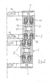
- FIG. 1 is a section of an energy guiding chain according to the invention with Untertrum 1 and upper strand 2 shown in view of the outside of one of the side strap strands.
- the strand consists for the most part of mutually equal side flaps 3. Included are roller-carrying side flap pairs 4, which consist of first side flaps 5 and second side flaps 6.
- the sectional view FIG. 2 corresponds to an operating condition in which the roles of Untertrum 1 and upper strand 2 are exactly superimposed.
- the guide portion 7 of the second side flap of the roll-carrying side flap pair extends into two cheeks 8, between which the tongue 9 of the first side flap is inserted. This is formed on both sides with pins 10, are mounted on the ball-bearing rollers 11, 12. These protrude with its peripheral region of the tread 16 and roll on the opposite tread.
- the tongue with the guide portion 7 is pivotally connected.
- the transverse webs 14 make the connection to the other side strap strand and together form with both strands the space for receiving the supply lines.
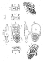
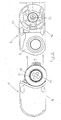
- FIG. 3 shows the first side flap of the roller-carrying side flap pair in orientation in the lower run 1 in plan view (ie on the tread 16) a), rear view (ie from the inside of the chain link) c), bottom view f), front view g), left side view b), right Side view d), section II-II e), and the rear view in perspective to the left h) and right i).
- the tongue 9 with the pin 10 serves the Receiving the rollers (not shown here)
- the area 22 under the outer surface 20 serves for connection to the other mutually equal side tabs by means of the recess 18, which can receive a corresponding pivot pin.
- the holes 21 in the pin 10 are provided for screws for fixing a disc, not shown here.
- transverse webs 14 FIG. 2 ) are plugged.
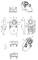
- FIG. 4 shows the second side flap of the roll-carrying side flap pair in orientation in the lower run 1 in plan view (ie on the tread 16) a), rear view (ie from the inside of the chain link) c), bottom view f), front view g), left side view b), right side view d), section II-II e), and the rear view in perspective to the left h) and right i).
- the guide portion 7 extends into the cheeks 8, which are provided with openings 24 for receiving the mounting plate, not shown here.
- the connecting portion 25 is provided here in the middle with a pivot pin 26 which can be accommodated in a receptacle of an adjacent side tab, the receptacle 18 (FIG. FIG. 3 ) corresponds.
- the connection region 25 on the second side flap is thus complementary to the connection region 22 on the first side flap.
- the smooth outer surface 23 of the connection region points here to the interior of the chain link.
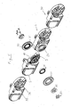
- FIG. 5 shows an exploded view of the roller-carrying side flap pair of first and second side flap 5 and 6 and two at its two ends of adjacent tabs 30 of a side strap strand of the energy supply chain according to the invention.
- the tongue 9 of the first side flap 5 rollers 32 are attached, which are provided with ball bearings Thereafter, the tongue 9 is guided between the cheeks 8 on the second side flap 6 and the first side flap 5 on the second 6 by means of the in the Opening 24 inserted and screwed with screws 33 on the tongue 9 slices 15 pivotally mounted.
- FIG. 6 shows the alignment of the first and second side tabs 5 and 6 prior to insertion of the tongue 9 between the cheeks 8, after the rollers 32 were fitted with the ball bearings 31 on the pin 10.
- the axis of the pivot axis between the second side flap 6 and the adjacent flap 30 (FIG. FIG. 5 ) is to be seen with respect to the narrow sides 16 and 35 of the side strap strand.
- the pivot pin 26 is namely the narrow side with the tread 16 closer than the opposite narrow side 35 (a ⁇ b). This achieves that the running surfaces 16 of the adjacent side flaps do not interfere with the pivoting.
Landscapes
- Engineering & Computer Science (AREA)
- General Engineering & Computer Science (AREA)
- Mechanical Engineering (AREA)
- Electric Cable Arrangement Between Relatively Moving Parts (AREA)
- Transmission Devices (AREA)
- Transmissions By Endless Flexible Members (AREA)
- Hydraulic Turbines (AREA)
- Devices For Conveying Motion By Means Of Endless Flexible Members (AREA)
- Supports For Pipes And Cables (AREA)
Claims (14)
- Chaîne d'acheminement d'énergie destinée au guidage de flexibles, de câbles et d'autres dispositifs similaires comprenant un certain nombre de maillons articulés entre eux et formés par des pattes latérales (3) parallèles reliées entre elles en chaînes de pattes latérales, et par des traverses (14) les reliant, lesdites pattes latérales (3) pouvant pivoter l'une contre l'autre autour d'un axe de pivotement commun de deux pattes latérales voisines, la chaîne d'acheminement d'énergie pouvant être déplacée de manière à ce qu'elle forme un brin supérieur (2), un brin inférieur (1) et une zone de renvoi reliant les deux brins, le brin supérieur reposant sur le brin inférieur, et des galets de roulement (11, 12) étant prévus sur au moins quelques maillons de chaîne du brin supérieur et/ou du brin inférieur en étant agencés de manière à pouvoir rouler, lors d'un mouvement de déplacement de la chaîne d'acheminement d'énergie, sur des surfaces de roulement (16) prévues sur les maillons de chaîne du brin opposé, caractérisée en ce que l'axe de rotation de chacun des galets de roulement (11, 12) coïncide avec l'axe de pivotement d'une paire voisine (4) des pattes latérales (5, 6).
- Chaîne d'acheminement d'énergie selon la revendication 1, caractérisée en ce que des maillons munis de galets de roulement ont la même longueur que les maillons pas munis de galets de roulement.
- Chaîne d'acheminement d'énergie selon les revendications 1 ou 2, caractérisée en ce que les galets de roulement sont disposés sur la face extérieure des maillons, et en ce que sur les faces intérieures des boucles des pattes latérales sont prévus des élargissements en tant que des surfaces de roulement (16) pour les galets de roulement.
- Chaîne d'acheminement d'énergie selon les revendications 1 à 3, caractérisée en ce que les galets de roulement sont incorporés dans l'intérieur des pattes latérales.
- Chaîne d'acheminement d'énergie selon les revendications 1 ou 4, caractérisée en ce que les chaînes de pattes latérales majoritairement consistent en pattes se ressemblant et comportant une partie coudée vers l'intérieur et vers l'extérieur, et en ce que des pattes latérales portant des galets de roulement sont incorporées en paires dans les chaînes.
- Chaîne d'acheminement d'énergie selon la revendication 5, caractérisée en ce que les paires de pattes latérales portant des galets de roulement se composent- d'une première patte latérale comprenant une partie pouvant être reliée à une patte latérale pas munie de galets de roulement, et une languette portant au moins un galet de roulement, et- d'une deuxième patte latérale comprenant une partie pouvant être reliée à une patte latérale pas munie de galets de roulement, et une partie de guidage à laquelle ladite languette peut être reliée d'une telle manière que les deux pattes latérales peuvent pivoter autour d'un axe qui coïncide avec l'axe du galet de roulement.
- Chaîne d'acheminement d'énergie selon la revendication 6, caractérisée en ce que les parties de la première et la deuxième patte qui peuvent être reliées aux pattes latérales pas munies de galets de roulement sont complémentaires entre elles.
- Chaîne d'acheminement d'énergie selon les revendications 6 ou 7, caractérisée en ce que la partie de guidage se compose d'une ou de deux joues destinées à recevoir des moyens pour le raccordement pivotant de ladite languette.
- Chaîne d'acheminement d'énergie selon la revendication 8, caractérisée en ce que la languette peut être insérée entre deux joues, l'un au moins des galets de roulement saillant en partie hors de la partie de guidage.
- Chaîne d'acheminement d'énergie selon l'une des revendications 6 à 9, caractérisée en ce que sont prévus deux galets de roulement montés aux deux côtés de la languette.
- Chaîne d'acheminement d'énergie selon l'une des revendications 6 à 10, caractérisée en ce que les galets de roulement sont enfichés dans des bouchons sur ladite languette.
- Chaîne d'acheminement d'énergie selon l'une des revendications 6 à 11, caractérisée en ce les galets der roulement sont supportés par des paliers à billes.
- Chaîne d'acheminement d'énergie selon l'une des revendications 7 à 12, caractérisée en ce les moyens pour le raccordement de la languette sont en forme de disques pouvant être insérées dans un orifice correspondant de la joue et fixées à la languette.
- Chaîne d'acheminement d'énergie selon l'une des revendications précédentes, caractérisée en ce que l'axe de pivotement pour les deux pattes latérales voisines est situé plus proche de la surface de roulement (16) que du côté étroit (35) des pattes latérales opposées à la surface der roulement.
Applications Claiming Priority (2)
| Application Number | Priority Date | Filing Date | Title |
|---|---|---|---|
| DE202006006645U DE202006006645U1 (de) | 2006-04-21 | 2006-04-21 | Energieführungskette |
| PCT/DE2007/000677 WO2007121715A1 (fr) | 2006-04-21 | 2007-04-17 | Chaîne d'acheminement d'énergie |
Publications (2)
| Publication Number | Publication Date |
|---|---|
| EP2010802A1 EP2010802A1 (fr) | 2009-01-07 |
| EP2010802B1 true EP2010802B1 (fr) | 2014-01-15 |
Family
ID=36710276
Family Applications (1)
| Application Number | Title | Priority Date | Filing Date |
|---|---|---|---|
| EP07722235.4A Active EP2010802B1 (fr) | 2006-04-21 | 2007-04-17 | Chaine d'acheminement d'energie |
Country Status (8)
| Country | Link |
|---|---|
| US (1) | US7497072B2 (fr) |
| EP (1) | EP2010802B1 (fr) |
| JP (1) | JP4830118B2 (fr) |
| KR (1) | KR101075698B1 (fr) |
| CN (1) | CN101460766B (fr) |
| DE (2) | DE202006006645U1 (fr) |
| TW (1) | TWI314195B (fr) |
| WO (1) | WO2007121715A1 (fr) |
Cited By (4)
| Publication number | Priority date | Publication date | Assignee | Title |
|---|---|---|---|---|
| DE202014105940U1 (de) | 2014-12-09 | 2015-01-07 | Igus Gmbh | Haspelvorrichtung für mindestens eine Leitung und Versorgungseinrichtung mit dieser Haspelvorrichtung |
| WO2022123308A1 (fr) | 2020-12-10 | 2022-06-16 | Igus Gmbh | Chaînes porte-câbles pour déplacements importants, comprenant notamment des galets de roulement |
| US20240026953A1 (en) * | 2020-12-10 | 2024-01-25 | Igus Gmbh | Energy chains for long travels, in particular with rollers |
| EP3983699B1 (fr) | 2019-06-17 | 2024-05-22 | Tsubaki Kabelschlepp GmbH | Dispositif de guidage de lignes |
Families Citing this family (15)
| Publication number | Priority date | Publication date | Assignee | Title |
|---|---|---|---|---|
| DE202006006638U1 (de) * | 2006-04-21 | 2006-06-22 | Igus Gmbh | Energieführungskette |
| DE202006006640U1 (de) * | 2006-04-21 | 2006-07-06 | Igus Gmbh | Energieführungskette |
| DE202006006645U1 (de) | 2006-04-21 | 2006-07-06 | Igus Gmbh | Energieführungskette |
| KR101020761B1 (ko) | 2010-10-15 | 2011-03-09 | 씨피시스템(주) | 케이블 체인용 롤러어셈블리 |
| WO2012113884A1 (fr) * | 2011-02-24 | 2012-08-30 | Basf Se | Dispositifs d'éclairage d'un nouveau type |
| DE202011004762U1 (de) | 2011-04-04 | 2011-09-07 | Igus Gmbh | Energieführungskette |
| DE202012003903U1 (de) * | 2012-04-19 | 2012-05-25 | Igus Gmbh | Energieführungskette mit Rollen |
| DE202012003908U1 (de) * | 2012-04-19 | 2012-05-15 | Igus Gmbh | Energieführungskette mit Rollen |
| US9032667B2 (en) * | 2013-07-10 | 2015-05-19 | Anthony International | Access system for a temperature controlled storage device |
| JP6262627B2 (ja) * | 2014-09-24 | 2018-01-17 | 株式会社椿本チエイン | ケーブル類保護案内装置 |
| US10367339B2 (en) * | 2017-05-10 | 2019-07-30 | The Boeing Company | Snag mitigating cable track apparatus |
| DE202017105644U1 (de) | 2017-09-18 | 2017-10-30 | Igus Gmbh | Energieführungskette mit Laufrollen |
| DE202018102144U1 (de) * | 2018-04-18 | 2019-05-27 | Igus Gmbh | Energieführungskette mit Dämpfungselementen sowie Seitenteil dafür |
| DE202019107117U1 (de) * | 2019-12-19 | 2021-04-19 | Igus Gmbh | Energieführungskette und Speichereinheit für eine Energieführungskette |
| KR20240116802A (ko) * | 2021-12-10 | 2024-07-30 | 이구스 게엠베하 | 플레인 베어링 링을 갖는 에너지 체인 |
Citations (1)
| Publication number | Priority date | Publication date | Assignee | Title |
|---|---|---|---|---|
| WO2007121713A1 (fr) * | 2006-04-21 | 2007-11-01 | Igus Gmbh | Chaîne d'acheminement d'énergie |
Family Cites Families (23)
| Publication number | Priority date | Publication date | Assignee | Title |
|---|---|---|---|---|
| US3284036A (en) * | 1965-05-06 | 1966-11-08 | Nat Crane Corp | Carrier link chain assembly for hoses |
| US3716986A (en) * | 1970-10-21 | 1973-02-20 | Gemco Electric Co | Rolling conductor support |
| US3779003A (en) * | 1972-09-07 | 1973-12-18 | Measurex Corp | Cable carrier with removable plastic links |
| GB1444307A (en) | 1974-10-01 | 1976-07-28 | Borjesson Kv | Chain construction |
| DE2656638A1 (de) * | 1976-12-14 | 1978-06-15 | Kurt Hennig | Bewegliche abdeckung fuer energiefuehrungsleitungen, fuehrungsbahnen und sonstige einrichtungen |
| US4373324A (en) | 1980-09-02 | 1983-02-15 | Maysteel Corporation | Guide apparatus for flexible elements connected to relatively moving units |
| US4392344A (en) * | 1981-06-30 | 1983-07-12 | Central Safety Equipment Company | Chain-link cable carrier |
| JPS60125441A (ja) * | 1983-12-06 | 1985-07-04 | Matsushita Electric Ind Co Ltd | ケ−ブルドラツグチエ−ン |
| DE4313075C2 (de) | 1993-04-21 | 1996-07-25 | Igus Gmbh | Energieführungskette |
| FR2723627B3 (fr) | 1994-08-11 | 1996-07-12 | Murrplastik Systemtechnik Gmbh | Chaine de guidage pour conducteurs d'energie |
| DE19512088C2 (de) * | 1995-04-03 | 1997-05-07 | Igus Gmbh | Energiekette |
| CN2261545Y (zh) * | 1996-10-31 | 1997-09-03 | 威海特种电源研究所 | 一种电缆移动装置 |
| DE19701706C1 (de) * | 1997-01-21 | 1998-09-03 | Igus Gmbh | Energiezuführungskette |
| DE19715531C2 (de) * | 1997-04-14 | 1999-05-27 | Igus Gmbh | Energieführungskette |
| WO1999057457A1 (fr) | 1998-05-05 | 1999-11-11 | Igus Spritzgussteile für die Industrie GmbH | Chaine de guidage d'elements de transport d'energie |
| DE19839270C2 (de) * | 1998-05-05 | 2000-10-26 | Igus Gmbh | Energieführungskette |
| DE19919076C2 (de) | 1999-04-19 | 2001-08-30 | Igus Gmbh | Energieführungskette |
| JP2001221293A (ja) * | 2000-02-07 | 2001-08-17 | Kunimori Kagaku Co Ltd | ケーブルチェーン |
| JP4266745B2 (ja) * | 2003-08-18 | 2009-05-20 | 株式会社椿本チエイン | ケーブル類保護案内装置 |
| DE10343263A1 (de) | 2003-09-17 | 2005-05-04 | Murrplastik Systemtechnik Gmbh | Seitenglied für ein Kettenglied einer Energieführungskette |
| DE102004022512A1 (de) | 2004-05-05 | 2005-12-01 | Kabelschlepp Gmbh | Kettenglied für eine Energieführungskette sowie Energieführungskette mit erweitertem Nutzungsquerschnitt |
| FR2875065A1 (fr) | 2004-09-03 | 2006-03-10 | Valeo Electronique Sys Liaison | Dispositif de support et de guidage de conducteurs electriques meplats |
| DE202006006645U1 (de) | 2006-04-21 | 2006-07-06 | Igus Gmbh | Energieführungskette |
-
2006
- 2006-04-21 DE DE202006006645U patent/DE202006006645U1/de not_active Expired - Lifetime
-
2007
- 2007-04-17 EP EP07722235.4A patent/EP2010802B1/fr active Active
- 2007-04-17 JP JP2009505716A patent/JP4830118B2/ja active Active
- 2007-04-17 WO PCT/DE2007/000677 patent/WO2007121715A1/fr not_active Ceased
- 2007-04-17 DE DE112007001536T patent/DE112007001536A5/de not_active Withdrawn
- 2007-04-17 KR KR1020087028452A patent/KR101075698B1/ko active Active
- 2007-04-17 CN CN200780020428.0A patent/CN101460766B/zh active Active
- 2007-04-20 TW TW096113871A patent/TWI314195B/zh active
- 2007-04-20 US US11/738,164 patent/US7497072B2/en active Active
Patent Citations (1)
| Publication number | Priority date | Publication date | Assignee | Title |
|---|---|---|---|---|
| WO2007121713A1 (fr) * | 2006-04-21 | 2007-11-01 | Igus Gmbh | Chaîne d'acheminement d'énergie |
Cited By (8)
| Publication number | Priority date | Publication date | Assignee | Title |
|---|---|---|---|---|
| DE202014105940U1 (de) | 2014-12-09 | 2015-01-07 | Igus Gmbh | Haspelvorrichtung für mindestens eine Leitung und Versorgungseinrichtung mit dieser Haspelvorrichtung |
| EP3983699B1 (fr) | 2019-06-17 | 2024-05-22 | Tsubaki Kabelschlepp GmbH | Dispositif de guidage de lignes |
| WO2022123308A1 (fr) | 2020-12-10 | 2022-06-16 | Igus Gmbh | Chaînes porte-câbles pour déplacements importants, comprenant notamment des galets de roulement |
| DE202021004122U1 (de) | 2020-12-10 | 2022-09-15 | Igus Gmbh | Energieführungsketten für lange Verfahrwege, insbesondere mit Laufrollen |
| US20240026953A1 (en) * | 2020-12-10 | 2024-01-25 | Igus Gmbh | Energy chains for long travels, in particular with rollers |
| US12584538B2 (en) * | 2020-12-10 | 2026-03-24 | Igus Gmbh | Energy chains for long travels, in particular with rollers |
| EP4722560A2 (fr) | 2020-12-10 | 2026-04-08 | igus SE & Co. KG | Chaînes de transport d'énergie pour longues courses, en particulier avec des galets de roulement |
| EP4726233A2 (fr) | 2020-12-10 | 2026-04-15 | igus SE & Co. KG | Chaîne de guidage d'énergie pour longues courses, en particulier avec galets de roulement |
Also Published As
| Publication number | Publication date |
|---|---|
| TW200745466A (en) | 2007-12-16 |
| EP2010802A1 (fr) | 2009-01-07 |
| KR101075698B1 (ko) | 2011-10-21 |
| US20070246600A1 (en) | 2007-10-25 |
| TWI314195B (en) | 2009-09-01 |
| WO2007121715A1 (fr) | 2007-11-01 |
| CN101460766A (zh) | 2009-06-17 |
| DE202006006645U1 (de) | 2006-07-06 |
| DE112007001536A5 (de) | 2009-04-02 |
| JP2009534593A (ja) | 2009-09-24 |
| US7497072B2 (en) | 2009-03-03 |
| KR20090014167A (ko) | 2009-02-06 |
| CN101460766B (zh) | 2014-07-16 |
| JP4830118B2 (ja) | 2011-12-07 |
Similar Documents
| Publication | Publication Date | Title |
|---|---|---|
| WO2007121715A1 (fr) | Chaîne d'acheminement d'énergie | |
| EP1076784B1 (fr) | Chaine de guidage d'elements de transport d'energie | |
| EP1359343B1 (fr) | Chaîne porteuse pour lignes de transport d'énergie | |
| DE3027834C2 (de) | Laschenkette für stufenlos verstellbare Kegelscheibengetriebe | |
| EP2010800B1 (fr) | Chaine d'acheminement d'energie | |
| EP2010801B1 (fr) | Chaine d'acheminement d'energie | |
| DE3990222B4 (de) | Raupenfahrwerk | |
| DE2914067A1 (de) | Rollenkette | |
| WO2013156469A1 (fr) | Chaîne porte-câbles à rouleaux | |
| EP1466108A1 (fr) | Dispositif pour acheminer l'energie a forces de frottement reduites | |
| CH703149B1 (de) | Rollenantriebselement. | |
| EP0731040B1 (fr) | Convoyeur à bande articulé avec tension prédéterminée de l'organe de support | |
| DE69932640T2 (de) | Fahrtreppe | |
| DE19932636B4 (de) | Drehzapfen | |
| DE4001529A1 (de) | Tragkette, insbesondere staurollentragkette | |
| DE3878400T2 (de) | Gliederkette fuer stufenlos regelbare getriebe mit gekruemmten gelenkstuecken. | |
| DE102007009821A1 (de) | Mehrreihige Kraftübertragungskette | |
| DE10137939A1 (de) | Schubkette für den Antrieb über ein Kettenrad sowie Antriebseinheit | |
| EP1090696B2 (fr) | Dispositif d'entrainement à chaines pour tréfilage en continu | |
| DE2209032C3 (de) | Schleppkette | |
| DE10109190C2 (de) | Gliederkette | |
| EP1069344B1 (fr) | Chaínes à maillons en plaques à articulations à faible usure | |
| EP1280973A1 (fr) | Charniere de porte | |
| EP4259951B1 (fr) | Chaînes porte-câbles pour déplacements importants, comprenant notamment des galets de roulement | |
| DE102006029530A1 (de) | Schlitten für eine Kabelführungskette |
Legal Events
| Date | Code | Title | Description |
|---|---|---|---|
| PUAI | Public reference made under article 153(3) epc to a published international application that has entered the european phase |
Free format text: ORIGINAL CODE: 0009012 |
|
| 17P | Request for examination filed |
Effective date: 20081023 |
|
| AK | Designated contracting states |
Kind code of ref document: A1 Designated state(s): AT BE BG CH CY CZ DE DK EE ES FI FR GB GR HU IE IS IT LI LT LU LV MC MT NL PL PT RO SE SI SK TR |
|
| AX | Request for extension of the european patent |
Extension state: AL BA HR MK RS |
|
| 17Q | First examination report despatched |
Effective date: 20090212 |
|
| DAX | Request for extension of the european patent (deleted) | ||
| RBV | Designated contracting states (corrected) |
Designated state(s): DE FR GB IT |
|
| GRAP | Despatch of communication of intention to grant a patent |
Free format text: ORIGINAL CODE: EPIDOSNIGR1 |
|
| INTG | Intention to grant announced |
Effective date: 20130829 |
|
| GRAS | Grant fee paid |
Free format text: ORIGINAL CODE: EPIDOSNIGR3 |
|
| GRAA | (expected) grant |
Free format text: ORIGINAL CODE: 0009210 |
|
| AK | Designated contracting states |
Kind code of ref document: B1 Designated state(s): DE FR GB IT |
|
| REG | Reference to a national code |
Ref country code: GB Ref legal event code: FG4D Free format text: NOT ENGLISH |
|
| REG | Reference to a national code |
Ref country code: DE Ref legal event code: R096 Ref document number: 502007012707 Country of ref document: DE Effective date: 20140227 |
|
| REG | Reference to a national code |
Ref country code: DE Ref legal event code: R097 Ref document number: 502007012707 Country of ref document: DE |
|
| PLBE | No opposition filed within time limit |
Free format text: ORIGINAL CODE: 0009261 |
|
| STAA | Information on the status of an ep patent application or granted ep patent |
Free format text: STATUS: NO OPPOSITION FILED WITHIN TIME LIMIT |
|
| 26N | No opposition filed |
Effective date: 20141016 |
|
| REG | Reference to a national code |
Ref country code: DE Ref legal event code: R097 Ref document number: 502007012707 Country of ref document: DE Effective date: 20141016 |
|
| REG | Reference to a national code |
Ref country code: FR Ref legal event code: PLFP Year of fee payment: 10 |
|
| REG | Reference to a national code |
Ref country code: FR Ref legal event code: PLFP Year of fee payment: 11 |
|
| REG | Reference to a national code |
Ref country code: FR Ref legal event code: PLFP Year of fee payment: 12 |
|
| P01 | Opt-out of the competence of the unified patent court (upc) registered |
Effective date: 20230526 |
|
| PGFP | Annual fee paid to national office [announced via postgrant information from national office to epo] |
Ref country code: DE Payment date: 20250624 Year of fee payment: 19 |
|
| PGFP | Annual fee paid to national office [announced via postgrant information from national office to epo] |
Ref country code: IT Payment date: 20250430 Year of fee payment: 19 |
|
| PGFP | Annual fee paid to national office [announced via postgrant information from national office to epo] |
Ref country code: FR Payment date: 20250422 Year of fee payment: 19 |
|
| REG | Reference to a national code |
Ref country code: DE Ref legal event code: R081 Ref document number: 502007012707 Country of ref document: DE Owner name: IGUS SE & CO. KG, DE Free format text: FORMER OWNER: IGUS GMBH, 51147 KOELN, DE |
|
| PGFP | Annual fee paid to national office [announced via postgrant information from national office to epo] |
Ref country code: GB Payment date: 20260324 Year of fee payment: 20 |