EP2010808B1 - Doppelsperrventil für schlauchboote - Google Patents
Doppelsperrventil für schlauchboote Download PDFInfo
- Publication number
- EP2010808B1 EP2010808B1 EP07761431.1A EP07761431A EP2010808B1 EP 2010808 B1 EP2010808 B1 EP 2010808B1 EP 07761431 A EP07761431 A EP 07761431A EP 2010808 B1 EP2010808 B1 EP 2010808B1
- Authority
- EP
- European Patent Office
- Prior art keywords
- valve
- cap
- spout
- opening
- web portion
- Prior art date
- Legal status (The legal status is an assumption and is not a legal conclusion. Google has not performed a legal analysis and makes no representation as to the accuracy of the status listed.)
- Active
Links
Images


Classifications
-
- F—MECHANICAL ENGINEERING; LIGHTING; HEATING; WEAPONS; BLASTING
- F16—ENGINEERING ELEMENTS AND UNITS; GENERAL MEASURES FOR PRODUCING AND MAINTAINING EFFECTIVE FUNCTIONING OF MACHINES OR INSTALLATIONS; THERMAL INSULATION IN GENERAL
- F16K—VALVES; TAPS; COCKS; ACTUATING-FLOATS; DEVICES FOR VENTING OR AERATING
- F16K15/00—Check valves
- F16K15/20—Check valves specially designed for inflatable bodies, e.g. tyres
- F16K15/205—Check valves specially designed for inflatable bodies, e.g. tyres and with closure plug
-
- F—MECHANICAL ENGINEERING; LIGHTING; HEATING; WEAPONS; BLASTING
- F16—ENGINEERING ELEMENTS AND UNITS; GENERAL MEASURES FOR PRODUCING AND MAINTAINING EFFECTIVE FUNCTIONING OF MACHINES OR INSTALLATIONS; THERMAL INSULATION IN GENERAL
- F16K—VALVES; TAPS; COCKS; ACTUATING-FLOATS; DEVICES FOR VENTING OR AERATING
- F16K15/00—Check valves
- F16K15/20—Check valves specially designed for inflatable bodies, e.g. tyres
- F16K15/202—Check valves specially designed for inflatable bodies, e.g. tyres and with flexible valve member
Definitions
- the present invention is directed to inflatable products, and more specifically to a valve for an inflatable product.
- An airbed is a large rectangular rubber or plastic bag that is filled with air so that it may be used as a bed.
- An air mat is similar in construction to an airbed, but is used as a float so that an individual may lie on the air mat in the water. Both products fall under the broad category of "inflatable" products.
- Other nonlimiting examples of inflatable products include rafts, inflatable furniture, inflatable pools, and inflatable boats.
- a valve or valves are supplied on an inflatable product for a user to provide air or another gas into the inflatable product.
- the user may utilize his or her breath, i.e., by blowing into a valve or valves, may utilize a manual or electric pump, or may use an air compressor, as examples.
- valves are presently used for inflatable products. These valves have a common goal: to permit the user to easily inflate and deflate the product, while minimizing escaped air when the user tries to seal the product. Examples of present day valves are the pinch valve, the Boston valve, and a double lock valve sold by the assignee of the present invention, The Coleman Company, Inc.
- valves work well for their intended purpose, very few valves are useful in both allowing simple inflation and deflation of the product and allowing quick closure so that air is not lost from the inflatable product after the inflatable product is full. That is, for most prior art valves, when a user has inflated a product, a cap or other structure must be placed over the valve before air is lost. Often, a substantial amount of air is lost before the valve is sufficiently closed. Additionally, the valve may be difficult to use for deflation of the inflatable product.
- a valve for an inflatable product.
- the valve includes an outer piece having a flexible cone or webbing that permits the outer piece of the valve to collapse into an inner piece of the valve.
- the outer piece includes a spout that fits onto a plug on the inner piece.
- the outer piece also includes an internal cylindrical flange that extends downward from the inside of the flexible cone and fits onto the plug.
- a cap is connected to the valve via a flap.
- the cap is a separate structure from the flap, and is formed of a more rigid material than the flap. The cap fits into the spout to provide a second, separate locking function.
- the cap may include a structure that may snap onto the plug, locking the valve into a double lock position.
- the cap may include a structure, such as threads, allowing it to screw into or onto the plug, locking the valve into a double lock position.
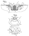
- a prior art inflating valve 2 is shown to comprise an outer piece 3 and an inner piece 4 which are disposed in a mounting hole 10 of a wall of an inflatable 1, for example, a cushion, a swimming ring, an airbed, or the like, and which are attached to the wall of the inflatable 1 and a fixing layer 11.
- the prior art valve 2 shown in FIGS. 1 and 2 is disclosed in Canadian published application number 2,238,593 .
- the outer piece 3 is made of a flexible plastic material and comprises a central tubular spout 30, a flexible web portion 31 formed around the tubular spout 31, and a peripheral flange 310 formed around the web portion 31 for cementing to the wall of the inflatable 1.
- the web portion 31 has a frusto-conical shape and includes a wider end connected to the peripheral flange 310 and a narrower end connected to the tubular spout 30.
- the web portion 31 is capable of flexing at the wider end to project into or outward of the inflatable 1.
- the inner piece 4 is made of a plastic material more rigid than that used for the outer piece 3, and comprises a central plug 40 to be press fitted in the tubular spout 30, a web portion 42 formed around the central plug 40, and a peripheral flange 41 formed around the web portion 42 for cementing to the peripheral flange 310 and the wall of the inflatable 1.
- the web portion 42 is generally frusto-conical and projects inwardly from the peripheral flange 41.
- the wider outer end of the web portion 42 is connected to the peripheral flange 41, and the narrower inner end thereof is connected to an inner end of the central plug 40, thereby holding the central plug 40 within the interior space of the web portion 42.
- a plurality of passage holes 420 are formed in the web portion 42 at different angular positions, and ribs 421 project outward from the outer surface of the web portion 42.
- the web portion 31 of the outer piece 3 can be pushed inward and placed in abutment with the web portion 42 of the inner piece 4 to cover the passage holes 420 when the tubular spout 30 is press fitted into the plug 40.
- the tubular spout 30 has an outer end portion 301 which extends axially and outwardly of the outer end of the plug 40 so that the plug 40 is entirely received in the tubular spout 30.
- a radially projecting annular flange 302 is formed at the outer end portion 301 for handling.
- the annular flange 302 is knurled to avoid slippage during handling. By pulling the annular flange 302, the tubular spout 30 can be removed from the plug 40.
- the tubular spout 30 may be configured such that the passage confined thereby slightly diverges inward so as to facilitate insertion or separation of the plug 40.
- the tubular spout 30 of the outer piece 3 is pushed inward to be sleeved on the plug 40, thereby blocking the tubular spout 30 and causing the web portion 31 to abut against the web portion 42 and to cover the passage holes 420.
- the inflating valve is in a closed position under this situation.
- the tubular spout 30 when the inflatable is inflated or deflated, the tubular spout 30 is pulled outward and the web portion 31 is separated from the web portion 42, thereby forming a space between the web portions 31 and 42 to communicate the tubular spout 30 and the passage holes 420.
- the inflating valve is thereby opened and permits air to flow into or out of the inflatable through the tubular spout 30 and the passage holes 420.
- FIG. 4 shows a valve 50 in accordance with an embodiment of the present invention.
- the valve 50 includes an outer piece 52 and an inner piece 54.
- the outer piece 52 includes a web portion 58 in the shape of a cone and extending upward from an outer peripheral flange 59 to a spout 60.
- a flap 62 is attached to one side of the spout 60 and terminates in a pull-tab 64.
- the web portion 58 of the outer piece 52 is sufficiently flexible so that the web portion may be collapsed by a user pressing inward on the spout 60.
- the web portion 58 is configured to hold itself in position at this collapsed state and user intervention is required to return the web portion to the extended state shown in FIG. 4 .
- the user may grasp the spout 60 or the flap 62 to pull outward on the spout 60.
- the web portion 58 To collapse the web portion 58, a user may push inward on the spout 60.
- the web portion 58 includes a shelf 68 on an upward tier. To this end, the shelf 68 is at a position at which the web portion 58 folds inward on itself when in the collapsed position. The shelf 68 also contributes to uniform collapsing of the web portion 58 so that the spout 60 aligns with a plug 88 in the inner piece 54.
- valve 50 includes a downwardly extending cylindrical flange 70 (also shown in FIG. 5 ) that serves as an extension of the interior of the spout 60.
- the cylindrical flange 70 adds additional locking power relative to the prior art valve 2 described above.
- the addition of the flange 70 permits the spout 60 and/or the flange 70 to form firm contact with the plug 88.
- the flange 70 is sufficiently thick to provide a firm, airtight connection by itself.
- the web portion 58 does not have to collapse as far as the prior art valve 1 for airtight locking of the valve. Pushing the web portion down so that the flange 70 and the spout 60 both have contact with the plug 88 enhances the airtight lock.
- the flap 62 includes an opening 72.
- This opening 72 is sized to receive a cap 74.
- the cap 74 includes a grooved annular notch 76 that snaps the cap into place, trapping the flap 62 and holding the cap into position in the opening 72.
- the inner piece 54 includes a bottom webbing 80 having spokes 82 leading to a central hub 84. Air openings 86 are provided between the spokes, and provide a path for air when the spout 60 is not connected to the plug 88.
- the plug 88 extends upward from the central hub 84.
- the outer piece 52 and the inner piece 54 are both formed of a material that is weldable or heat fusible to the inflatable for which the valve is attached.
- the inflatable, the outer piece 52 and the inner piece 54 are all formed of vinyl.
- the inner piece 54 includes wall thicknesses that allow areas to be more rigid for sealing and fit.
- the spokes 82, the central hub 84, and the plug 88 are sufficiently thick to maintain the plug in a fixed position.
- the outer piece 52 includes walls having thicknesses that allow particular areas, such as the spout 60 and the flange 70, to be more rigid, and other areas to be thinner, for example at the web portion 54 and the flap 62.
- a one step process may be used for attaching the valve 52 to an inflatable product. That is, the peripheral flange 59 of the outer piece 52 may be aligned against an upper or outer portion of the inflatable product, and an outer peripheral flange 78 for the inner piece 54 may be aligned against an inner surface of the inflatable product.
- the three layers are then welded together.
- This process is in contrast to the prior art valve 2 described above, in which the inner piece 4 is formed of Acrylonitrile Butadiene Styrene (ABS), and an intermediate layer is attached to the inner piece, and the intermediate layer is then attached to the inflatable 1.
- ABS Acrylonitrile Butadiene Styrene
- the cap 74 is formed separately from the outer piece 52 (and therefore the flap 62), the cap may be formed of a separate material than the outer piece.
- the cap is formed of a more rigid material than the outer piece 52, e.g., ABS.
- Other materials may be used, but preferably the cap 74 is a rigid or semi-rigid material.
- a second airtight seal is formed by the cap 74 extending into the top end of the spout 60.
- the semirigid or rigid material used for the cap 74 permits the cap to maintain consistent pressure outward against the inside edges of the spout 60, thus providing a separate airtight locking function that is independent of the attachment of the spout 60 and flange 70 to the plug 88.
- the cap 74 and the plug 66 may include features that allow the two structures to lock into one another when the valve 50 is closed.
- one of the cap 74 and the plug 88 may include a ball, with the other having a socket.
- Other attachment structures may be used, including, but not limited to, snaps, magnets, clips, or other features.
- FIG. 8 shows an alternate embodiment of a valve 150, in accordance with an embodiment.
- the valve 150 may be similar in structure, composition, and function to the valve 50.
- the valve 150 may include an outer piece 152 and an inner piece 154.
- the outer piece 152 may include a web portion 158, an outer peripheral flange 159, and a spout 60.
- a flap 162 may be included that may terminate in a pull tab 164 and may be attached to the spout 160.
- the flap 162 may include an opening 172.
- the web portion 158 may include a shelf 168.
- the valve 150 may include a cylindrical flange 170 and a cap 174.
- the inner piece 154 may include a bottom webbing 180 having spokes 182 that lead to a central hub 184, air openings 186, and a plug 188.
- the cap 174 may be made from ABS plastic or other suitable materials. As seen in FIG. 8 , the cap 174 includes threads 190 running along its outer surface.
- the spout 160 includes threads 192 running along its inner surface and configured to receive the threads 190 of the cap 174 in a manner such that the cap 174 may be screwed into the spout 160.
- the cap 174 and spout 160 may alternatively be configured so that the cap 174 has threads running along an inner surface and the spout 160 has threads running along its outer surface, the threads of the spout being configured to receive the threads of the cap 174 so that the cap 174 may be screwed onto the spout 160.
- the threads 190 engage the threads 192 and provide a tight fit so that the cap 174 prevents or resists the flow of air or water between the cap 174 and the spout 160.
- the threads 190, 192 lock the cap 174 in place.
- the valve 150 is operated similarly to the valve 50, as described above.
- the cap 174 is screwed into the spout 160 and the spout 160 is pressed inward until the valve 150 is in a collapsed state.
- the spout 160 or the flap 162 may be grasped and pulled outward and the cap 174 may be unscrewed from the spout 160.
Landscapes
- Engineering & Computer Science (AREA)
- General Engineering & Computer Science (AREA)
- Mechanical Engineering (AREA)
- Check Valves (AREA)
- Bag Frames (AREA)
Claims (12)
- Ventil (50, 150) für ein aufblasbares Produkt (1), Folgendes umfassend:ein Innenteil (54, 154), einen Stopfen umfassend;ein Außenteil (52, 152), Folgendes umfassend:einen flexiblen Gewebeabschnitt (31), der von einer ersten Position in eine zweite Position zusammengeschoben werden kann;eine Öffnung (72, 172), wobei die Öffnung, wenn der flexible Gewebeabschnitt (31) in der zweiten Position ist, mehr in Richtung des Innenteils (54, 154) des Ventils (50, 150) liegt, als in der ersten Position, wobei die Öffnung (72, 172) auf den Stopfen (88, 188) auf dem Innenteil (54, 154) passt, wenn sich der flexible Gewebeabschnitt (31) in der zweiten Position befindet; undeinen innenliegenden zylindrischen Flansch (70, 170), der sich um die Öffnung (72, 172) herum und aus dem Außenteil (52, 152) heraus in Richtung des Innenteils (54) erstreckt, und der konfiguriert ist, um auf den Stopfen (88, 188) zu passen, wenn sich das Außenteil (52, 152) in der zweiten Position befindet;dadurch gekennzeichnet, dassder flexible Gewebeabschnitt (58, 158) einen Vorsprung (68, 168) auf einem ansteigenden Wandteil enthält.
- Ventil (50, 150) nach Anspruch 1, wobei der flexible Gewebeabschnitt (31) einen flexiblen Konus (58, 158) umfasst, und wobei die Öffnung (72, 172) eine zentrale Tülle (60, 160) im flexiblen Konus umfasst.
- Ventil (50, 150) nach Anspruch 2, darüber hinaus eine Kappe (74, 174) umfassend, die konfiguriert ist, um abnehmbar mit der Tülle (60, 160) verbunden zu werden, um die Luftströmung durch die Tülle (60, 160) hindurch zu verhindern.
- Ventil (50, 150) nach Anspruch 3, wobei die Tülle (60, 160) einen Gewindeabschnitt enthält und die Kappe (74, 174) konfiguriert ist, um mit dem Gewindeabschnitt verschraubt zu werden.
- Ventil (50, 150) nach Anspruch 4, darüber hinaus eine Lasche (62, 162) umfassend, die mit dem Außenteil (52, 152) verbunden ist und mit der Kappe (74, 174) verbunden ist.
- Ventil (50, 150) nach Anspruch 5, wobei die Lasche (62, 162) eine Öffnung (72, 172) umfasst, und die Kappe (74, 174) einen ringförmigen Flansch (70, 170) zur Aufnahme der Öffnung (72, 172) umfasst.
- Ventil (50, 150) nach Anspruch 5, wobei die Kappe (74, 174) aus einem ersten Material gebildet wird, und die Lasche (62, 162) aus einem zweiten Material gebildet wird, und wobei das erste Material starrer ist, als das zweite Material.
- Ventil (50, 150) nach Anspruch 1, darüber hinaus eine Kappe (74, 174) umfassend, die konfiguriert ist, um abnehmbar in der Öffnung (72, 172) angebracht zu werden, um die Luftströmung durch die Öffnung (72, 172) zu verhindern.
- Ventil (50, 150) nach Anspruch 8, wobei die Öffnung (72, 172) einen Gewindeabschnitt enthält und die Kappe (74, 174) konfiguriert ist, um mit dem Gewindeabschnitt verschraubt zu werden.
- Ventil (50, 150) nach Anspruch 9, darüber hinaus eine Lasche (52, 152) umfassend, die mit dem Außenteil (52, 152) verbunden ist und mit der Kappe (74, 174) verbunden ist.
- Ventil (50, 150) nach Anspruch 10, wobei die Lasche (62, 162) eine Öffnung (72, 172) umfasst, und die Kappe (74, 174) einen ringförmigen Flansch (70, 170) zur Aufnahme der Öffnung (72, 172) umfasst.
- Ventil (50, 150) nach Anspruch 10, wobei die Kappe (74, 174) aus einem ersten Material gebildet wird, und die Lasche (62, 162) aus einem zweiten Material gebildet wird, und wobei das erste Material starrer ist, als das zweite Material.
Applications Claiming Priority (3)
| Application Number | Priority Date | Filing Date | Title |
|---|---|---|---|
| US74576406P | 2006-04-27 | 2006-04-27 | |
| US90966907P | 2007-04-02 | 2007-04-02 | |
| PCT/US2007/067605 WO2007127907A2 (en) | 2006-04-27 | 2007-04-27 | Double lock valve for inflatables |
Publications (3)
| Publication Number | Publication Date |
|---|---|
| EP2010808A2 EP2010808A2 (de) | 2009-01-07 |
| EP2010808A4 EP2010808A4 (de) | 2011-05-04 |
| EP2010808B1 true EP2010808B1 (de) | 2016-11-09 |
Family
ID=38656407
Family Applications (1)
| Application Number | Title | Priority Date | Filing Date |
|---|---|---|---|
| EP07761431.1A Active EP2010808B1 (de) | 2006-04-27 | 2007-04-27 | Doppelsperrventil für schlauchboote |
Country Status (5)
| Country | Link |
|---|---|
| EP (1) | EP2010808B1 (de) |
| CN (1) | CN101454601B (de) |
| AU (1) | AU2007244748A1 (de) |
| CA (1) | CA2650712C (de) |
| WO (1) | WO2007127907A2 (de) |
Families Citing this family (1)
| Publication number | Priority date | Publication date | Assignee | Title |
|---|---|---|---|---|
| GB201401497D0 (en) * | 2014-01-29 | 2014-03-12 | Jackel Int Ltd | Valve assembly |
Family Cites Families (6)
| Publication number | Priority date | Publication date | Assignee | Title |
|---|---|---|---|---|
| US4004614A (en) * | 1975-08-01 | 1977-01-25 | Halkey-Roberts Corporation | Tether for captive plug of inflation device |
| CH684359A5 (de) * | 1991-09-19 | 1994-08-31 | Arthur Max Peter | Automatisch schliessendes Ventil an einem aufblasbaren Körper. |
| AUPP284298A0 (en) * | 1998-04-06 | 1998-04-30 | Segal, Colin | Self-inflating cushion and valve therefor |
| US6460560B1 (en) * | 2000-01-28 | 2002-10-08 | Halkey-Roberts Corporation | Low profile inflation valve |
| DE20004836U1 (de) * | 2000-03-08 | 2001-07-19 | Auergesellschaft Gmbh, 12059 Berlin | Feedinganordnung für Atemschutzmasken zur Nahrungs- und Getränkeaufnahme im Einsatz |
| US6386247B1 (en) * | 2001-02-20 | 2002-05-14 | Helmut Richard Elze | Valve for a dunnage bag |
-
2007
- 2007-04-27 WO PCT/US2007/067605 patent/WO2007127907A2/en not_active Ceased
- 2007-04-27 CA CA2650712A patent/CA2650712C/en active Active
- 2007-04-27 AU AU2007244748A patent/AU2007244748A1/en not_active Abandoned
- 2007-04-27 CN CN2007800196621A patent/CN101454601B/zh active Active
- 2007-04-27 EP EP07761431.1A patent/EP2010808B1/de active Active
Also Published As
| Publication number | Publication date |
|---|---|
| CA2650712A1 (en) | 2007-11-08 |
| AU2007244748A1 (en) | 2007-11-08 |
| CN101454601B (zh) | 2012-06-06 |
| CN101454601A (zh) | 2009-06-10 |
| EP2010808A2 (de) | 2009-01-07 |
| CA2650712C (en) | 2014-02-25 |
| WO2007127907A3 (en) | 2008-07-17 |
| EP2010808A4 (de) | 2011-05-04 |
| WO2007127907A2 (en) | 2007-11-08 |
Similar Documents
| Publication | Publication Date | Title |
|---|---|---|
| US20080223449A1 (en) | Valve for an inflatable product | |
| US3995653A (en) | Inflation device | |
| US8540495B2 (en) | Dual duty hand pump | |
| EP1721551B1 (de) | Aufblasbares Bett mit intergrierter Pumpe | |
| CA2703032C (en) | Vacuum container having air release valve cover | |
| US6408453B1 (en) | Inflatable swimming pool assembly | |
| US4004614A (en) | Tether for captive plug of inflation device | |
| CN107542951B (zh) | 用于充气/放气的阀 | |
| US20100108182A1 (en) | Devices and methods for preserving liquids, paints, and other materials | |
| EP2010808B1 (de) | Doppelsperrventil für schlauchboote | |
| US20100096572A1 (en) | Air Valve | |
| HK1127387B (en) | Double lock valve for inflatables | |
| HK1127387A (en) | Double lock valve for inflatables | |
| AU2013260667A1 (en) | Double lock valve for inflatables | |
| US8192245B2 (en) | Vent seal for inflatable devices | |
| US20160220034A1 (en) | Air Inflation Accelerator | |
| AU2006320257A1 (en) | Valve for an inflatable product | |
| WO2005116496A1 (en) | Valve for an inflatable product | |
| CN219242721U (zh) | 一种充泄气一体式气嘴结构 | |
| US20070246680A1 (en) | Air valve structure for inflatable articles | |
| CN221857540U (zh) | 一种气阀及充气产品 | |
| HK1126539A (en) | Valve for an inflatable product | |
| CN204553972U (zh) | 一种充气阀 | |
| CN219796245U (zh) | 一种扭转充排式气嘴 | |
| CN210611651U (zh) | 一种快速充气垫 |
Legal Events
| Date | Code | Title | Description |
|---|---|---|---|
| PUAI | Public reference made under article 153(3) epc to a published international application that has entered the european phase |
Free format text: ORIGINAL CODE: 0009012 |
|
| 17P | Request for examination filed |
Effective date: 20081028 |
|
| AK | Designated contracting states |
Kind code of ref document: A2 Designated state(s): AT BE BG CH CY CZ DE DK EE ES FI FR GB GR HU IE IS IT LI LT LU LV MC MT NL PL PT RO SE SI SK TR |
|
| AX | Request for extension of the european patent |
Extension state: AL BA HR MK RS |
|
| DAX | Request for extension of the european patent (deleted) | ||
| REG | Reference to a national code |
Ref country code: HK Ref legal event code: DE Ref document number: 1127387 Country of ref document: HK |
|
| A4 | Supplementary search report drawn up and despatched |
Effective date: 20110404 |
|
| RIC1 | Information provided on ipc code assigned before grant |
Ipc: A47C 27/08 20060101ALI20110329BHEP Ipc: F16K 15/20 20060101AFI20081028BHEP |
|
| RIC1 | Information provided on ipc code assigned before grant |
Ipc: F16K 15/20 20060101AFI20160422BHEP Ipc: A47C 27/08 20060101ALI20160422BHEP |
|
| GRAP | Despatch of communication of intention to grant a patent |
Free format text: ORIGINAL CODE: EPIDOSNIGR1 |
|
| INTG | Intention to grant announced |
Effective date: 20160630 |
|
| GRAS | Grant fee paid |
Free format text: ORIGINAL CODE: EPIDOSNIGR3 |
|
| GRAA | (expected) grant |
Free format text: ORIGINAL CODE: 0009210 |
|
| AK | Designated contracting states |
Kind code of ref document: B1 Designated state(s): AT BE BG CH CY CZ DE DK EE ES FI FR GB GR HU IE IS IT LI LT LU LV MC MT NL PL PT RO SE SI SK TR |
|
| REG | Reference to a national code |
Ref country code: GB Ref legal event code: FG4D |
|
| REG | Reference to a national code |
Ref country code: AT Ref legal event code: REF Ref document number: 844259 Country of ref document: AT Kind code of ref document: T Effective date: 20161115 Ref country code: CH Ref legal event code: EP |
|
| REG | Reference to a national code |
Ref country code: IE Ref legal event code: FG4D |
|
| REG | Reference to a national code |
Ref country code: DE Ref legal event code: R096 Ref document number: 602007048660 Country of ref document: DE |
|
| REG | Reference to a national code |
Ref country code: NL Ref legal event code: FP |
|
| PG25 | Lapsed in a contracting state [announced via postgrant information from national office to epo] |
Ref country code: LV Free format text: LAPSE BECAUSE OF FAILURE TO SUBMIT A TRANSLATION OF THE DESCRIPTION OR TO PAY THE FEE WITHIN THE PRESCRIBED TIME-LIMIT Effective date: 20161109 |
|
| REG | Reference to a national code |
Ref country code: LT Ref legal event code: MG4D |
|
| REG | Reference to a national code |
Ref country code: AT Ref legal event code: MK05 Ref document number: 844259 Country of ref document: AT Kind code of ref document: T Effective date: 20161109 |
|
| REG | Reference to a national code |
Ref country code: FR Ref legal event code: PLFP Year of fee payment: 11 |
|
| PG25 | Lapsed in a contracting state [announced via postgrant information from national office to epo] |
Ref country code: LT Free format text: LAPSE BECAUSE OF FAILURE TO SUBMIT A TRANSLATION OF THE DESCRIPTION OR TO PAY THE FEE WITHIN THE PRESCRIBED TIME-LIMIT Effective date: 20161109 Ref country code: GR Free format text: LAPSE BECAUSE OF FAILURE TO SUBMIT A TRANSLATION OF THE DESCRIPTION OR TO PAY THE FEE WITHIN THE PRESCRIBED TIME-LIMIT Effective date: 20170210 Ref country code: SE Free format text: LAPSE BECAUSE OF FAILURE TO SUBMIT A TRANSLATION OF THE DESCRIPTION OR TO PAY THE FEE WITHIN THE PRESCRIBED TIME-LIMIT Effective date: 20161109 |
|
| PG25 | Lapsed in a contracting state [announced via postgrant information from national office to epo] |
Ref country code: FI Free format text: LAPSE BECAUSE OF FAILURE TO SUBMIT A TRANSLATION OF THE DESCRIPTION OR TO PAY THE FEE WITHIN THE PRESCRIBED TIME-LIMIT Effective date: 20161109 Ref country code: PT Free format text: LAPSE BECAUSE OF FAILURE TO SUBMIT A TRANSLATION OF THE DESCRIPTION OR TO PAY THE FEE WITHIN THE PRESCRIBED TIME-LIMIT Effective date: 20170309 Ref country code: IS Free format text: LAPSE BECAUSE OF FAILURE TO SUBMIT A TRANSLATION OF THE DESCRIPTION OR TO PAY THE FEE WITHIN THE PRESCRIBED TIME-LIMIT Effective date: 20170309 Ref country code: ES Free format text: LAPSE BECAUSE OF FAILURE TO SUBMIT A TRANSLATION OF THE DESCRIPTION OR TO PAY THE FEE WITHIN THE PRESCRIBED TIME-LIMIT Effective date: 20161109 Ref country code: AT Free format text: LAPSE BECAUSE OF FAILURE TO SUBMIT A TRANSLATION OF THE DESCRIPTION OR TO PAY THE FEE WITHIN THE PRESCRIBED TIME-LIMIT Effective date: 20161109 Ref country code: PL Free format text: LAPSE BECAUSE OF FAILURE TO SUBMIT A TRANSLATION OF THE DESCRIPTION OR TO PAY THE FEE WITHIN THE PRESCRIBED TIME-LIMIT Effective date: 20161109 |
|
| PGFP | Annual fee paid to national office [announced via postgrant information from national office to epo] |
Ref country code: NL Payment date: 20170426 Year of fee payment: 11 |
|
| PG25 | Lapsed in a contracting state [announced via postgrant information from national office to epo] |
Ref country code: CZ Free format text: LAPSE BECAUSE OF FAILURE TO SUBMIT A TRANSLATION OF THE DESCRIPTION OR TO PAY THE FEE WITHIN THE PRESCRIBED TIME-LIMIT Effective date: 20161109 Ref country code: EE Free format text: LAPSE BECAUSE OF FAILURE TO SUBMIT A TRANSLATION OF THE DESCRIPTION OR TO PAY THE FEE WITHIN THE PRESCRIBED TIME-LIMIT Effective date: 20161109 Ref country code: RO Free format text: LAPSE BECAUSE OF FAILURE TO SUBMIT A TRANSLATION OF THE DESCRIPTION OR TO PAY THE FEE WITHIN THE PRESCRIBED TIME-LIMIT Effective date: 20161109 Ref country code: SK Free format text: LAPSE BECAUSE OF FAILURE TO SUBMIT A TRANSLATION OF THE DESCRIPTION OR TO PAY THE FEE WITHIN THE PRESCRIBED TIME-LIMIT Effective date: 20161109 Ref country code: DK Free format text: LAPSE BECAUSE OF FAILURE TO SUBMIT A TRANSLATION OF THE DESCRIPTION OR TO PAY THE FEE WITHIN THE PRESCRIBED TIME-LIMIT Effective date: 20161109 |
|
| REG | Reference to a national code |
Ref country code: DE Ref legal event code: R097 Ref document number: 602007048660 Country of ref document: DE |
|
| PG25 | Lapsed in a contracting state [announced via postgrant information from national office to epo] |
Ref country code: IT Free format text: LAPSE BECAUSE OF FAILURE TO SUBMIT A TRANSLATION OF THE DESCRIPTION OR TO PAY THE FEE WITHIN THE PRESCRIBED TIME-LIMIT Effective date: 20161109 Ref country code: BG Free format text: LAPSE BECAUSE OF FAILURE TO SUBMIT A TRANSLATION OF THE DESCRIPTION OR TO PAY THE FEE WITHIN THE PRESCRIBED TIME-LIMIT Effective date: 20170209 |
|
| PGFP | Annual fee paid to national office [announced via postgrant information from national office to epo] |
Ref country code: BE Payment date: 20170427 Year of fee payment: 11 |
|
| PLBE | No opposition filed within time limit |
Free format text: ORIGINAL CODE: 0009261 |
|
| STAA | Information on the status of an ep patent application or granted ep patent |
Free format text: STATUS: NO OPPOSITION FILED WITHIN TIME LIMIT |
|
| 26N | No opposition filed |
Effective date: 20170810 |
|
| REG | Reference to a national code |
Ref country code: HK Ref legal event code: GR Ref document number: 1127387 Country of ref document: HK |
|
| PG25 | Lapsed in a contracting state [announced via postgrant information from national office to epo] |
Ref country code: SI Free format text: LAPSE BECAUSE OF FAILURE TO SUBMIT A TRANSLATION OF THE DESCRIPTION OR TO PAY THE FEE WITHIN THE PRESCRIBED TIME-LIMIT Effective date: 20161109 |
|
| REG | Reference to a national code |
Ref country code: CH Ref legal event code: PL |
|
| REG | Reference to a national code |
Ref country code: IE Ref legal event code: MM4A |
|
| PG25 | Lapsed in a contracting state [announced via postgrant information from national office to epo] |
Ref country code: MC Free format text: LAPSE BECAUSE OF FAILURE TO SUBMIT A TRANSLATION OF THE DESCRIPTION OR TO PAY THE FEE WITHIN THE PRESCRIBED TIME-LIMIT Effective date: 20161109 |
|
| PG25 | Lapsed in a contracting state [announced via postgrant information from national office to epo] |
Ref country code: LU Free format text: LAPSE BECAUSE OF NON-PAYMENT OF DUE FEES Effective date: 20170427 Ref country code: LI Free format text: LAPSE BECAUSE OF NON-PAYMENT OF DUE FEES Effective date: 20170430 Ref country code: CH Free format text: LAPSE BECAUSE OF NON-PAYMENT OF DUE FEES Effective date: 20170430 |
|
| REG | Reference to a national code |
Ref country code: FR Ref legal event code: PLFP Year of fee payment: 12 |
|
| PG25 | Lapsed in a contracting state [announced via postgrant information from national office to epo] |
Ref country code: IE Free format text: LAPSE BECAUSE OF NON-PAYMENT OF DUE FEES Effective date: 20170427 |
|
| PG25 | Lapsed in a contracting state [announced via postgrant information from national office to epo] |
Ref country code: MT Free format text: LAPSE BECAUSE OF NON-PAYMENT OF DUE FEES Effective date: 20170427 |
|
| REG | Reference to a national code |
Ref country code: NL Ref legal event code: MM Effective date: 20180501 |
|
| REG | Reference to a national code |
Ref country code: BE Ref legal event code: FP Effective date: 20170202 Ref country code: BE Ref legal event code: MM Effective date: 20180430 |
|
| PG25 | Lapsed in a contracting state [announced via postgrant information from national office to epo] |
Ref country code: NL Free format text: LAPSE BECAUSE OF NON-PAYMENT OF DUE FEES Effective date: 20180501 |
|
| PG25 | Lapsed in a contracting state [announced via postgrant information from national office to epo] |
Ref country code: BE Free format text: LAPSE BECAUSE OF NON-PAYMENT OF DUE FEES Effective date: 20180430 |
|
| PG25 | Lapsed in a contracting state [announced via postgrant information from national office to epo] |
Ref country code: HU Free format text: LAPSE BECAUSE OF FAILURE TO SUBMIT A TRANSLATION OF THE DESCRIPTION OR TO PAY THE FEE WITHIN THE PRESCRIBED TIME-LIMIT; INVALID AB INITIO Effective date: 20070427 |
|
| PG25 | Lapsed in a contracting state [announced via postgrant information from national office to epo] |
Ref country code: CY Free format text: LAPSE BECAUSE OF NON-PAYMENT OF DUE FEES Effective date: 20161109 |
|
| PG25 | Lapsed in a contracting state [announced via postgrant information from national office to epo] |
Ref country code: TR Free format text: LAPSE BECAUSE OF FAILURE TO SUBMIT A TRANSLATION OF THE DESCRIPTION OR TO PAY THE FEE WITHIN THE PRESCRIBED TIME-LIMIT Effective date: 20161109 |
|
| REG | Reference to a national code |
Ref country code: DE Ref legal event code: R082 Ref document number: 602007048660 Country of ref document: DE Representative=s name: METACOM LEGAL, DE |
|
| REG | Reference to a national code |
Ref country code: DE Ref legal event code: R082 Ref document number: 602007048660 Country of ref document: DE |
|
| PGFP | Annual fee paid to national office [announced via postgrant information from national office to epo] |
Ref country code: DE Payment date: 20250429 Year of fee payment: 19 |
|
| PGFP | Annual fee paid to national office [announced via postgrant information from national office to epo] |
Ref country code: GB Payment date: 20250428 Year of fee payment: 19 |
|
| PGFP | Annual fee paid to national office [announced via postgrant information from national office to epo] |
Ref country code: FR Payment date: 20250425 Year of fee payment: 19 |