EP2010848B1 - Optimierung und steuerung des gefriertrocknungsverfahrens pharmazeutischer produkte - Google Patents
Optimierung und steuerung des gefriertrocknungsverfahrens pharmazeutischer produkte Download PDFInfo
- Publication number
- EP2010848B1 EP2010848B1 EP07735443.9A EP07735443A EP2010848B1 EP 2010848 B1 EP2010848 B1 EP 2010848B1 EP 07735443 A EP07735443 A EP 07735443A EP 2010848 B1 EP2010848 B1 EP 2010848B1
- Authority
- EP
- European Patent Office
- Prior art keywords
- model
- temperature
- lyophilisation
- observer
- container
- Prior art date
- Legal status (The legal status is an assumption and is not a legal conclusion. Google has not performed a legal analysis and makes no representation as to the accuracy of the status listed.)
- Not-in-force
Links
- NAZUYXOIDCMQAA-UHFFFAOYSA-N CCC1C2C1CCC2 Chemical compound CCC1C2C1CCC2 NAZUYXOIDCMQAA-UHFFFAOYSA-N 0.000 description 1
Images


Classifications
-
- G—PHYSICS
- G01—MEASURING; TESTING
- G01K—MEASURING TEMPERATURE; MEASURING QUANTITY OF HEAT; THERMALLY-SENSITIVE ELEMENTS NOT OTHERWISE PROVIDED FOR
- G01K1/00—Details of thermometers not specially adapted for particular types of thermometer
- G01K1/02—Means for indicating or recording specially adapted for thermometers
- G01K1/024—Means for indicating or recording specially adapted for thermometers for remote indication
-
- F—MECHANICAL ENGINEERING; LIGHTING; HEATING; WEAPONS; BLASTING
- F26—DRYING
- F26B—DRYING SOLID MATERIALS OR OBJECTS BY REMOVING LIQUID THEREFROM
- F26B5/00—Drying solid materials or objects by processes not involving the application of heat
- F26B5/04—Drying solid materials or objects by processes not involving the application of heat by evaporation or sublimation of moisture under reduced pressure, e.g. in a vacuum
- F26B5/06—Drying solid materials or objects by processes not involving the application of heat by evaporation or sublimation of moisture under reduced pressure, e.g. in a vacuum the process involving freezing
-
- G—PHYSICS
- G01—MEASURING; TESTING
- G01N—INVESTIGATING OR ANALYSING MATERIALS BY DETERMINING THEIR CHEMICAL OR PHYSICAL PROPERTIES
- G01N33/00—Investigating or analysing materials by specific methods not covered by groups G01N1/00 - G01N31/00
- G01N33/15—Medicinal preparations ; Physical properties thereof, e.g. dissolubility
Definitions
- the present invention relates to a method for monitoring the lyophilisation process of pharmaceutical products contained in vials and ampoules.
- Lyophilisation is a well known drying process wherein the solvent, generally water, is removed by means of sublimation from the previously frozen product, by exploiting the combined action of low temperature and low pressure. It is useful to monitor the lyophilisation process in that this allows controlling the quality of the product and allows the development and implementation of specific optimisation and control strategies for the process itself.
- the temperature of the product is the most important variable to be monitored during the process. Indeed, the sublimation phase, known as primary drying, must be carried out at such a temperature as to avoid the formation of liquid, so that the fraction of the product already dried does not deteriorate thermally and break down.
- Another important process variable is the position of the sublimation front within the product subjected to lyophilisation, which moves during the process, travelling from the top of the container to the bottom, until it disappears as soon as the frozen solvent has been completely removed.
- monitoring the position of the sublimation interface allows determining the state of progression of the primary drying phase and allows the establishment of when the sublimation process has terminated.
- a first method consists of inserting a thermocouple inside the container.
- a thermocouple is inserted inside the container containing the product in the liquid state, generally placed in contact with the inner surface at the base of the container, or in another position.
- the value of the temperature measured is assumed to be representative of that of the entire product, even if a temperature gradient exists between the base of the container and the sublimation front, which is not known a priori.
- This measurement method is invasive, whereby the thermocouple disturbs both the exchanges of heat which are established between the various parts of the system and the physical freezing process.
- thermocouples can compromise the sterility of pharmaceutical products.
- a second method used involves measuring the temperature manometrically, and is known as "Manometric Temperature Measurement” (MTM).
- MTM Manometric Temperature Measurement
- This method is based on measuring the increased pressure which occurs in the system when the valve separating the lyophilisation chamber from the condenser is closed for a few moments.
- the condenser, or ice trap is a component of the lyophilisation device, the walls of which are maintained at a low temperature by means of the circulation of a refrigerant fluid.
- the temperature difference between the product and the temperature at the condenser represents the driving force behind the sublimation process.
- the vapour released from the product sublimes on the chilled condenser walls, thus maintaining the level of vacuum within the system.
- the lyophilisation device must be equipped with a condenser outside the lyophilisation chamber, the separation valve closure time must be extremely small, and measurement cannot be performed continuously, hence it provides discontinuous monitoring of the sublimation temperature; furthermore, it provides the mean value of all the vials and does not allow assessment of the non-uniformity between the vials or ampoules placed in different areas of the lyophilisation device.
- the temperature of the product has a tendency to increase, especially in the final phase of primary drying, thus exposing the product to risk of break-down. It is also known that said method is not capable of providing accurate sublimation temperature values at the end of primary drying.
- thermocouples By means of the former method, when the sublimation front passes the temperature sensor, the temperature profile shows a sloping variation. In this way, by using various different thermocouples, it is possible to follow the temporal progression of the position of the moving interface.
- this method implies the use of a plurality of thermocouples inside the product, which have an influence on the mechanism of nucleation occurring during the freezing phase. For this reason, the measurements obtained this way cannot be considered as an absolute indication of the conditions prevailing in the non-monitored containers.
- the simultaneous use of several thermocouples is limited to large sized containers only.
- KR 2002 0064036 A discloses a system for monitoring the temperature of a product in containers arranged inside a chamber, comprising a temperature measurement system associated with each container housed inside the chamber, capable of surveying local temperature data for each container, a wireless communication system for the temperature data surveyed, comprising means of transmission inside the chamber and means of receiving outside of it, and means of processing of said data, located externally to the chamber and arranged to determine an average temperature value correlated with a local temperature value of the container.
- An object of the present invention is that of allowing the realization of a method capable of determining the temperature profile and position of the sublimation front in real time during a lyophilisation process of substances contained in bottles, vials, small kegs, ampoules or similar containers.
- Figure 1 generally illustrates a system indicated by the number 2.
- Said system 2 comprises, for example, two bottles 4 containing the product to be lyophilised, a system for measuring the temperature 6, a wireless transmission system 8, capable of transmitting the measurements taken inside 10 the vacuum chamber of a lyophilisation system to the exterior 12 of said chamber, where said two environments are kept separate during the entire lyophilisation process.
- a computer 16 with a system for processing and displaying the measurements, programmed to continuously calculate and provide an operator with the temperature of the product and the progress of the moving sublimation interface.
- the temperature measuring system 6 has the following functions:
- the measurement system 6 is powered autonomously by means of a battery inside the lyophilisation chamber, or from outside the chamber using radiofrequency signals.
- FIG 2 shows two examples of temperature sensors.
- the temperature sensor 20 is placed in contact with the inner wall of the base 22 of the bottle.
- the temperature sensor 20 is placed in contact with the outer wall of the base 22 of the bottle.
- the temperature sensors 20 are thermocouples.
- the radiofrequency transmitter 8 located outside 12 the lyophilisation system is connected to the computer 16 by means of a serial connection.
- the measurement data transmitted to the computer 16, constituted by a single temperature measurement (internal or external) for each bottle being monitored (see figure 2 ), are processed by the processing and displaying system 16 capable of implementing a predetermined lyophilisation process model by means of a calculation algorithm based on the state observer concept (realization of a so-called software sensor).
- the software sensor combines the physical temperature measurement of the container wall, for example at the base 22 of the container (process input) with a selected mathematical model, preferably simplified, of the process, and returns as output a series of physical process parameters, including, in particular, the spatial product temperature profile, the sublimation front position and the values of the process matter and heat exchange coefficients.
- Two different types of models according to which the user selects to measure the container interior or exterior temperature, may be used.
- the product temperature is the most important parameter to be monitored and controlled. Indeed, primary drying should be carried out under controlled temperature conditions so as not to compromise the final product quality.
- the transfer of matter through the product and the transfer of heat between the heating element (plate) and the product are a further two critical aspects which influence drying time.
- the transfer of matter depends on the temperature, the pressure conditions and the resistance of the dry structure to vapour flux.
- Heat transfer mainly depends on the composition and pressure of the gaseous phase in the lyophilisation chamber and the geometry of the container in the area in contact with the heating element (plate).
- FIG. 3 A diagram of a vial, considered cylindrical, is shown in figure 3 . This figure shows only half of the vial since this approach assumes conditions of axial symmetry. Two distinct regions can be highlighted. Region 24 is a dry layer, which extends from the uppermost end of the vial to the sublimation interface 26. In the layer 24, the water has been essentially eliminated by means of sublimation, and partially by means of desorption, leaving a porous matrix through which the solvent (normally water vapour) is transported by means of diffusion and convection mechanisms. Region 28 consists of non-sublimed frozen solution.
- the moving interface 26 herein denoted by the function H(r,t), where t is the time and r is the distance from the central axis of the vial, recedes towards the base of the vial due to the sublimation of the product. If a heat flux q side is provided in a radial direction 30, as happens when there is irradiation from the chamber to the sides of the vial, the shape of the interface becomes curved.
- the interface When the interface reaches the base of the vial, at the maximum radial position 32, it begins to contract and finally degenerates to a point in the centre of the base.
- the product After the disappearance of the frozen layer 28-all the product is subjected to the secondary drying phase, which continues until the water residual content is reduced to the desired value.
- the model equations describe the temporal and spatial development of the temperature of the dry layer 24, T I , and of the frozen product 28, T II . Heat is transferred across the frozen mass by conduction, and across the dry layer by means of convection and conduction.
- FIG. 4 A diagram of the vial is shown in figure 4 .
- the moving interface 26, always denoted H, is planar following the assumption of one-dimensional geometry.
- the origin of the z axis 34 is placed at the uppermost end of the vial.
- the complete model equations have been obtained by performing the balance of matter and energy for the dry layer, the balance of energy for the frozen layer and the balance of matter and heat across the sublimation interface. Finally, the balance of energy within the wall of the vial has been performed.
- the one-dimensional model has been further simplified with the purpose of developing two reduced models capable of providing approximations, reasonably suitable for monitoring and controlling the process.
- the first reduced model (hereinafter referred to as reduced model I) is a relatively simple model, and is obtained by performing a balance of energy for the frozen product and a balance of matter for the water vapour contained in the dried product, both considered under pseudo-stationary conditions, having hypothesised slow process dynamics.
- N W z t - Mk 1 RT I z t ⁇ ⁇ ⁇ z ⁇ p W z t
- H(t) is the position of the moving sublimation front
- p w,i is expressed as a function of T i
- the mean dry layer temperature value has been approximated with the value of the interface temperature T i .
- K v includes the resistance to the transfer of heat across the base of the vial of thickness ⁇
- T plate is the temperature of the heating element (plate).
- q t - ⁇ ⁇ H s ⁇ N W t wherein ⁇ H s is the enthalpy of sublimation.
- the final equation connects the temperature and the interface position with the temperature measured at the base of the vial, while non-linear equation 13 provides a relationship between T i and H.
- the key parameters of the model are the matter transfer and heat transfer coefficients.
- the proposed model is a simplified model, since heat transfer in the dry state is not considered and energy transport in the frozen layer occurs under pseudo-stationary conditions, an approximation from which it is derived that all the energy transferred to the product is used for sublimation. Furthermore, the walls of the vial are assumed to be screened from the irradiation. It should be observed that in the complete model of the process, the energy originating from the heat plate is mainly transferred to the product across the base of the container, but is also partly transferred across the walls of the vial, as a consequence of the conduction across the glass. In the reduced model being the object of the invention, the presence of the vial is not considered and the energy originating from the heat plate only reaches the base of the product. Under such conditions, so that the reduced model gives the same results as the detailed model of the process, it is necessary to use an effective heat transfer coefficient, which includes the effect of heat conduction along the vial and irradiation, if present.
- the pseudostationary type model is similar to the URIF model described in the articles by Sandall, O.C., King, C.J., Wilke, C.R., "The Relationship Between Transport Properties and Rates of Freeze-Drying of Poultry Meat” in AIChE Journal, 1967, vol. 13(4), pp. 428-438 and Hill, J.E., Sunderland, J.E. "Sublimation-dehydration in the continuum, transition and free-molecule flow regimes", in Int. J. Heat and Mass Transfer, 1971, vol. 14, pp. 625-638 .
- T B is fundamentally important for the development of estimation strategies based on use of the reduced model.
- the second reduced model (hereinafter: reduced model II) is more complex with respect to the previously described model. Heat transfer is considered both across the frozen and dry layers, and across the vial walls, while matter transfer is modelled as per the previous model. The contribution of irradiation is not considered directly, and any effect is incorporated in the effective coefficient of heat transfer. Furthermore, the assumption of pseudostationary conditions allows the attainment of an analytical solution to the problem in the spatial domain.
- T I - 2 ⁇ 1 - a 1 ⁇ C 3 cosh ⁇ I ⁇ H ⁇ ⁇ + a I ⁇ C 6 T I
- gl + a II ⁇ C 1 ⁇ e - ⁇ II ⁇ L - H ⁇ ⁇ + C 2 ⁇ e ⁇
- the non-linear equation (32) relates the temperature at the interface with the position of the moving sublimation front, since C 1 , C 2 , C 5 are dependent on T i and H; the equation (33) allows expressing the temperature of the glass at the base of the vial as a function of T i and H.
- the reduced model presented in this section is derived formally from the complete model; both the energy transfer in the product and along the glass of the vial are modelled.
- the simplification introduced by the assumption of a pseudostationary state allows analytically resolving one part of the problem, leading to expressing the axial temperature profile along the product and along the vial by means of non-linear algebraic equations.
- Figure 5 shows the temperature profile of the product and the vial along the axial coordinates, at three different times during primary drying, and it can be observed how the differences between the estimates of the two models are very small and, in any case, always of the order of 0.1 K.
- an important objective of optimisation of the lyophilisation process is that of minimising human intervention, avoiding disturbing the process with invasive methods.
- This can be obtained by means of the development of an accurate and robust procedure for determining the temperature of the product without using physical sensors inserted inside the vial.
- another type of software-sensor has been synthesised that is capable of estimating the dynamics of the product temperature starting from reduced model II and performing a single temperature measurement outside the vial, i.e. by means of sensors that are not in direct contact with the product.
- Kalman filter is essentially a set of mathematical equations which implement a predictor-corrector type observer, which minimises the estimated error covariance, under predefined conditions.
- the application being the object of the invention is preceded by the synthesis of an extended Kalman type observer for each of the previously illustrated reduced models I and II.
- the observer estimates the dynamic of the temperature at the interface Ti at each time point during the primary drying phase, using the temperature at the base of the frozen product T B as the measured variable.
- the effective diffusion coefficient of the dry layer k 1 which has an influence on mass transfer, and the heat transfer coefficient between the heat plate and the base of the vial, K v , are considered unknown parameters and are themselves estimated, together with the interface temperature T i .
- T i , K v and k 1 the position of the interface may be calculated by means of equation (13).
- the observer may be provided using the temperature of the product as a physical measurement y measured at any axial position z and given by equation (8).
- T II z t K v ⁇ T plate t - T B t k II ⁇ z - L + T B t
- the observer may compensate for the variations in K v and k 1 through the action of correction terms of the dynamic of the estimated state K(t)( ⁇ -y) (refer to equation 43).
- Figure 6 shows a comparison of the predictions provided by the observer, with the temperature at the interface and the base of the product simulated by means of the detailed process model.
- the right hand side of the figure shows the development of the moving sublimation front over time.
- the parameters used in the complete model simulations are:
- the extended Kalman filter requires the solution of the Riccati dynamic equation (equation (46)) making it laborious from the viewpoint of computation time. To overcome this drawback, a high gain observer has been realized which does not require an additional dynamic equation in its formulation for the solution of the estimation problem.
- x ⁇ - 1 ⁇ S ⁇ - 1 ⁇ C T ⁇ y ⁇ - y y ⁇ h x u
- Figure 7 reports the results of the simulations performed with the synthesised high gain observer, using the same values used in fig. 6 for parameters K v and k 1 .
- a Kalman observer has also been developed for the reduced model II.
- the variables and parameters considered in the design of said observer are again the temperature and the position of the moving interface, and the heat and matter transfer parameters. With respect to the previously developed observer, the difference is the measured variable, in that here, the use of the vial wall external temperature has been selected. This is possible since the equations of the reduced model II allow the expression of the vial temperature, for example at the base of the container, as a function of the variables to be observed, i.e. the state of the system.
- the use of the container outer wall temperature measurement allows non-invasive monitoring of the process, thus overcoming the drawbacks associated with the use of the invasive measurement systems.
- the observer may be realized using the container exterior temperature measured at any axial position z and given by equation (23) or (25) as a physical measurement.
- Figure 8 reports the estimates of the temperature and the interface position provided by the Kalman observer for reduced model II, which show good agreement with the results obtained using the detailed model of the process as a real data source.
- the conditions and parameters used in the simulations are those reported above.
- the first advantage of this method is that by using only one sensor 20 it is possible to obtain an entire temperature profile of the product and so deduce the position of the sublimation front, thanks to the specific calculation algorithms implemented in the system of the data processor 16.
- the determination of product temperature is achieved non-invasively.
- This aspect is particularly important if the substance to be lyophilised requires operation in a sterile environment, as in this case, it would not be possible to insert thermocouples into the product due to potential contamination problems.
- a further advantage of the method consists in transmitting the measurements outside the lyophilisation device without the aid of electrical cables, using technology similar to that adopted in radiofrequency devices. This way, no connections are required between the interior and exterior of the lyophilisation chamber, through the special vacuum tap with which the lyophilisation device access port 14 is provided, making installation and use of the system extremely simple.
Landscapes
- Engineering & Computer Science (AREA)
- Health & Medical Sciences (AREA)
- Life Sciences & Earth Sciences (AREA)
- Molecular Biology (AREA)
- Mechanical Engineering (AREA)
- General Engineering & Computer Science (AREA)
- Physics & Mathematics (AREA)
- General Physics & Mathematics (AREA)
- Drying Of Solid Materials (AREA)
- Medical Preparation Storing Or Oral Administration Devices (AREA)
Claims (17)
- Verfahren zum Überwachen des Lyophilisierungsprozesses eines Produkts in Containern (4, 4a, 4b), die innerhalb einer Lyophilisierungskammer angeordnet sind, wobei das Verfahren gekennzeichnet ist durch Verwenden:- eines Temperaturmesssystems (6), das mit jedem Container, der innerhalb (10) der Lyophilisierungskammer beherbergt ist, assoziiert ist, das in der Lage ist Lokaltemperaturdaten für jeden Container zu untersuchen,- eines kabelloses Kommunikationssystems (8) für die untersuchten Temperaturdaten, das Übertragungseinrichtungen innerhalb der Kammer und Empfangseinrichtungen außerhalb von ihr umfasst; und- Prozessierungseinrichtungen (16) für diese Daten, die extern von der Lyophilisierungskammer lokalisiert sind,wobei das Verfahren ferner umfasst:Bestimmen zumindest eines Parameters, der für den Fortschritt des Lyophilisierungsprozesses indikativ ist, der nicht durch das Temperaturmesssystem gemessen wird, mittels eines vorherbestimmten Darstellungsmodells des Prozesses, das in der Lage ist, einen Lokaltemperaturwert des Containers mit dem Parameter zu korrelieren.
- Verfahren nach Anspruch 1, wobei das Temperaturmesssystem (6) Temperatursensoren (20), die auf der Innenseite der Containerwand positioniert sind, beinhaltet.
- Verfahren nach Anspruch 1, wobei das Temperaturmesssystem (6) Temperatursensoren (20), die auf der Außenseite der Containerwand positioniert sind, beinhaltet.
- Verfahren nach Ansprüchen 2 oder 3, wobei die Temperatursensoren (20) an der Basis (22) der Containerwand positioniert sind.
- Verfahren nach einem der vorangegangenen Ansprüche, wobei das kabellose Kommunikationssystem (8) Radiofrequenzübertragungs- und Empfangseinrichtungen umfasst.
- Verfahren nach einem der vorangegangenen Ansprüche, das Energieversorgungseinrichtungen für das kabellose Temperaturmesssystem mittels elektromagnetischer Wellen umfasst.
- Verfahren nach einem der vorangegangenen Ansprüche, wobei die Prozessierungseinrichtungen (16) programmiert sind, um eines aus einer Vielzahl von Lyophilisierungsprozess-repräsentierenden Modellen auszuwählen und um den zumindest einen Parameter zu bestimmen, der für den Fortschritt des Prozesses mittels eines auf das Modell angewendeten vorherbestimmten Zustandsbeobachter indikativ ist.
- Verfahren nach Anspruch 7, wobei ein erstes Modell (reduziertes Modell I) anwendbar ist, wenn die Temperatursensoren (20) auf der Innenseite der Containerwand positioniert sind.
- Verfahren nach Anspruch 7, wobei ein zweites Modell (reduziertes Modell II) anwendbar ist, wenn die Temperatursensoren (20) auf der Außenseite der Containerwand positioniert sind.
- Verfahren nach einem der vorangegangenen Ansprüche, wobei der Parameter, der für den Fortschritt des Lyophilisierungsprozesses indikativ ist, zumindest einen der folgenden umfasst: die Position der Sublimationsfront, die Temperaturverteilung in dem Volumen des Produkts in dem Container, den Materieaustauschkoeffizienten in der getrockneten Produktschicht, den Wärmeaustauschskoeffizienten an der Basis des Containers.
- Verfahren nach Anspruch 8, wobei das erste Modell durch die folgenden Gleichungen definiert ist:


- Verfahren nach Anspruch 9, wobei das zweite Modell durch die folgenden Gleichungen definiert ist:


wobei:
und die Integrationskonstanten sind:




wobei:
- Verfahren nach Ansprüchen 8 oder 9, wobei ein Zustandsbeobachter von der Art ist, der auf Kalman-Filtern basiert.
- Verfahren nach Anspruch 13, wobei ein Kalman-Beobachter für das erste Modell durch die folgenden Gleichungen definiert ist:
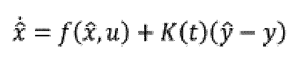

wobei:


- Verfahren nach Anspruch 13, wobei ein Kalman-Beobachter für das zweite Modell durch die folgenden Gleichungen definiert ist:


wobei: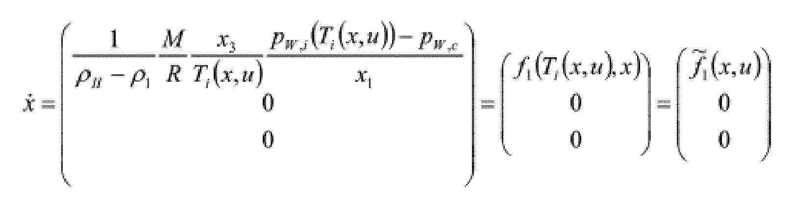


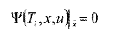
mit
- Verfahren nach Anspruch 9, wobei ein Zustandsbeobachter vom hochverstärkenden Typ ist.
- Verfahren nach Anspruch 16, wobei ein hochverstärkender Beobachter für das erste Modell durch die folgenden Gleichungen definiert ist:


wobei:


Applications Claiming Priority (2)
| Application Number | Priority Date | Filing Date | Title |
|---|---|---|---|
| IT000270A ITTO20060270A1 (it) | 2006-04-11 | 2006-04-11 | Ottimazione e controllo del processo di liofilizzazione di prodotti farmaceutici |
| PCT/IB2007/051276 WO2007116371A2 (en) | 2006-04-11 | 2007-04-10 | Optimization and control of the freeze-drying process of pharmaceutical products |
Publications (2)
| Publication Number | Publication Date |
|---|---|
| EP2010848A2 EP2010848A2 (de) | 2009-01-07 |
| EP2010848B1 true EP2010848B1 (de) | 2014-09-03 |
Family
ID=38581469
Family Applications (1)
| Application Number | Title | Priority Date | Filing Date |
|---|---|---|---|
| EP07735443.9A Not-in-force EP2010848B1 (de) | 2006-04-11 | 2007-04-10 | Optimierung und steuerung des gefriertrocknungsverfahrens pharmazeutischer produkte |
Country Status (4)
| Country | Link |
|---|---|
| US (1) | US8117005B2 (de) |
| EP (1) | EP2010848B1 (de) |
| IT (1) | ITTO20060270A1 (de) |
| WO (1) | WO2007116371A2 (de) |
Families Citing this family (15)
| Publication number | Priority date | Publication date | Assignee | Title |
|---|---|---|---|---|
| EP2034263A1 (de) * | 2007-09-06 | 2009-03-11 | BOC Edwards Pharmaceutical Systems | Gefriertrocknungskammer mit externer Antenne |
| IT1397930B1 (it) * | 2009-12-23 | 2013-02-04 | Telstar Technologies S L | Metodo per monitorare l'essiccamento primario di un processo di liofilizzazione. |
| GB2480299B (en) | 2010-05-12 | 2016-08-10 | Gea Pharma Systems Ltd | A method for monitoring and/or controlling process parameters of a lyophilization process |
| US8434240B2 (en) | 2011-01-31 | 2013-05-07 | Millrock Technology, Inc. | Freeze drying method |
| US9121637B2 (en) * | 2013-06-25 | 2015-09-01 | Millrock Technology Inc. | Using surface heat flux measurement to monitor and control a freeze drying process |
| US20150226617A1 (en) * | 2014-02-12 | 2015-08-13 | Millrock Technology, Inc | Using in-process heat flow and developing transferable protocols for the monitoring, control and characerization of a freeze drying process |
| JP6718879B2 (ja) * | 2015-01-28 | 2020-07-08 | アイエムエー ライフ ノース アメリカ インコーポレーテッド | 無バッテリのマルチポイント無線製品条件(状態)感知を用いるプロセス監視と制御 |
| DK3250869T3 (da) | 2015-01-28 | 2019-07-29 | Ima Life North America Inc | Processtyring under anvendelse af ikke-invasive printede produktsensorer |
| US10605527B2 (en) | 2015-09-22 | 2020-03-31 | Millrock Technology, Inc. | Apparatus and method for developing freeze drying protocols using small batches of product |
| US11828535B2 (en) * | 2018-06-29 | 2023-11-28 | Universiteit Gent | Freezing, drying and/or freeze-drying of product dose units |
| CN110645077B (zh) * | 2019-10-15 | 2021-11-02 | 黄冈师范学院 | 柴油机Urea-SCR系统氨喷射速率和状态同步估计方法 |
| US11287185B1 (en) | 2020-09-09 | 2022-03-29 | Stay Fresh Technology, LLC | Freeze drying with constant-pressure and constant-temperature phases |
| NL2026826B1 (en) * | 2020-11-04 | 2022-06-24 | Rheavita Bv | Method and apparatus for freezing or thawing mixtures comprising water |
| WO2022103745A1 (en) * | 2020-11-10 | 2022-05-19 | Purdue Research Foundation | System and method for measuring rapid decompression ice nucleation in lyophilization |
| US20260016226A1 (en) * | 2024-07-14 | 2026-01-15 | Frei Jonathan | Advanced lyophilization control interfaces and techniques |
Citations (1)
| Publication number | Priority date | Publication date | Assignee | Title |
|---|---|---|---|---|
| KR20020064036A (ko) * | 2001-01-31 | 2002-08-07 | 만도공조 주식회사 | 김치저장고의 평균온도 제어장치 및 그 방법 |
Family Cites Families (2)
| Publication number | Priority date | Publication date | Assignee | Title |
|---|---|---|---|---|
| JPS54134479A (en) * | 1978-04-10 | 1979-10-18 | Sharp Corp | Wireless temperature measuring device |
| US7520670B2 (en) * | 2005-04-26 | 2009-04-21 | John Jeffrey Schwegman | Wireless temperature sensing system for lyophilization processes |
-
2006
- 2006-04-11 IT IT000270A patent/ITTO20060270A1/it unknown
-
2007
- 2007-04-10 WO PCT/IB2007/051276 patent/WO2007116371A2/en not_active Ceased
- 2007-04-10 US US12/296,802 patent/US8117005B2/en not_active Expired - Fee Related
- 2007-04-10 EP EP07735443.9A patent/EP2010848B1/de not_active Not-in-force
Patent Citations (1)
| Publication number | Priority date | Publication date | Assignee | Title |
|---|---|---|---|---|
| KR20020064036A (ko) * | 2001-01-31 | 2002-08-07 | 만도공조 주식회사 | 김치저장고의 평균온도 제어장치 및 그 방법 |
Non-Patent Citations (1)
| Title |
|---|
| DATABASE WPI Week 200311, Derwent World Patents Index; AN 2003-117901 * |
Also Published As
| Publication number | Publication date |
|---|---|
| WO2007116371A3 (en) | 2008-02-21 |
| WO2007116371A2 (en) | 2007-10-18 |
| EP2010848A2 (de) | 2009-01-07 |
| WO2007116371A8 (en) | 2007-11-29 |
| ITTO20060270A1 (it) | 2007-10-12 |
| US8117005B2 (en) | 2012-02-14 |
| US20090276179A1 (en) | 2009-11-05 |
Similar Documents
| Publication | Publication Date | Title |
|---|---|---|
| EP2010848B1 (de) | Optimierung und steuerung des gefriertrocknungsverfahrens pharmazeutischer produkte | |
| Pikal et al. | Freeze-drying process development and scale-up: scale-up of edge vial versus center vial heat transfer coefficients, Kv | |
| Pikal et al. | The collapse temperature in freeze drying: Dependence on measurement methodology and rate of water removal from the glassy phase | |
| EP3575718B1 (de) | Verfahren zur überwachung und steuerung eines gefriertrocknungsprozesses in einer gefriertrocknungsvorrichtung | |
| Velardi et al. | Dynamic parameters estimation method: advanced manometric temperature measurement approach for freeze-drying monitoring of pharmaceutical solutions | |
| Barresi et al. | In-line control of the lyophilization process. A gentle PAT approach using software sensors | |
| Zhu et al. | Predictive models of lyophilization process for development, scale-up/tech transfer and manufacturing | |
| Leys et al. | A primary drying model-based comparison of conventional batch freeze-drying to continuous spin-freeze-drying for unit doses | |
| US11885564B2 (en) | Apparatus and method for developing freeze drying protocols using small batches of product | |
| Andrieu et al. | A review on experimental determination and optimization of physical quality factors during pharmaceuticals freeze-drying cycles | |
| Sane et al. | Spatial variation of pressure in the lyophilization product chamber part 2: experimental measurements and implications for scale-up and batch uniformity | |
| US20150226617A1 (en) | Using in-process heat flow and developing transferable protocols for the monitoring, control and characerization of a freeze drying process | |
| Bosca et al. | Freeze-drying monitoring using a new Process Analytical Technology: Toward a “zero defect” process | |
| Tchessalov et al. | Best practices and guidelines (2022) for scale-up and technology transfer in freeze drying based on case studies. Part 2: past practices, current best practices, and recommendations | |
| Geraldes et al. | A new perspective on scale-down strategies for freezing of biopharmaceutics by means of computational fluid dynamics | |
| Fissore et al. | PAT tools for the optimization of the freeze-drying process | |
| Kawasaki et al. | Temperature measurement by sublimation rate as a process analytical technology tool in lyophilization | |
| Chiou et al. | A comparison of crystallisation approaches in spray drying | |
| Zhou et al. | Leveraging lyophilization modeling for reliable development, scale-up and technology transfer | |
| Huang et al. | Moisture transport and diffusive instability during bread baking | |
| Galan | Monitoring and control of industrial freeze-drying operations: the challenge of implementing quality-by-design (QbD) | |
| Kamenik et al. | Determination of pressure resistance of a partially stoppered vial by using a coupled CFD-0D model of lyophilization | |
| US20150192357A1 (en) | Control of freezing and thawing of drug substances using heat flow control | |
| Pisano et al. | Insights into thermal interactions in frozen pharmaceutical vials: effects on ice nucleation times and inhibition | |
| Ehlers et al. | Impact of chamber wall temperature on energy transfer during freeze-drying |
Legal Events
| Date | Code | Title | Description |
|---|---|---|---|
| PUAI | Public reference made under article 153(3) epc to a published international application that has entered the european phase |
Free format text: ORIGINAL CODE: 0009012 |
|
| 17P | Request for examination filed |
Effective date: 20081107 |
|
| AK | Designated contracting states |
Kind code of ref document: A2 Designated state(s): AT BE BG CH CY CZ DE DK EE ES FI FR GB GR HU IE IS IT LI LT LU LV MC MT NL PL PT RO SE SI SK TR |
|
| AX | Request for extension of the european patent |
Extension state: AL BA HR MK RS |
|
| DAX | Request for extension of the european patent (deleted) | ||
| 17Q | First examination report despatched |
Effective date: 20120910 |
|
| GRAP | Despatch of communication of intention to grant a patent |
Free format text: ORIGINAL CODE: EPIDOSNIGR1 |
|
| INTG | Intention to grant announced |
Effective date: 20131107 |
|
| GRAP | Despatch of communication of intention to grant a patent |
Free format text: ORIGINAL CODE: EPIDOSNIGR1 |
|
| INTG | Intention to grant announced |
Effective date: 20140411 |
|
| GRAS | Grant fee paid |
Free format text: ORIGINAL CODE: EPIDOSNIGR3 |
|
| GRAA | (expected) grant |
Free format text: ORIGINAL CODE: 0009210 |
|
| AK | Designated contracting states |
Kind code of ref document: B1 Designated state(s): AT BE BG CH CY CZ DE DK EE ES FI FR GB GR HU IE IS IT LI LT LU LV MC MT NL PL PT RO SE SI SK TR |
|
| REG | Reference to a national code |
Ref country code: GB Ref legal event code: FG4D |
|
| REG | Reference to a national code |
Ref country code: AT Ref legal event code: REF Ref document number: 685830 Country of ref document: AT Kind code of ref document: T Effective date: 20140915 Ref country code: CH Ref legal event code: EP |
|
| REG | Reference to a national code |
Ref country code: IE Ref legal event code: FG4D |
|
| REG | Reference to a national code |
Ref country code: DE Ref legal event code: R096 Ref document number: 602007038404 Country of ref document: DE Effective date: 20141016 |
|
| REG | Reference to a national code |
Ref country code: AT Ref legal event code: MK05 Ref document number: 685830 Country of ref document: AT Kind code of ref document: T Effective date: 20140903 |
|
| PG25 | Lapsed in a contracting state [announced via postgrant information from national office to epo] |
Ref country code: LT Free format text: LAPSE BECAUSE OF FAILURE TO SUBMIT A TRANSLATION OF THE DESCRIPTION OR TO PAY THE FEE WITHIN THE PRESCRIBED TIME-LIMIT Effective date: 20140903 Ref country code: SE Free format text: LAPSE BECAUSE OF FAILURE TO SUBMIT A TRANSLATION OF THE DESCRIPTION OR TO PAY THE FEE WITHIN THE PRESCRIBED TIME-LIMIT Effective date: 20140903 Ref country code: GR Free format text: LAPSE BECAUSE OF FAILURE TO SUBMIT A TRANSLATION OF THE DESCRIPTION OR TO PAY THE FEE WITHIN THE PRESCRIBED TIME-LIMIT Effective date: 20141204 Ref country code: FI Free format text: LAPSE BECAUSE OF FAILURE TO SUBMIT A TRANSLATION OF THE DESCRIPTION OR TO PAY THE FEE WITHIN THE PRESCRIBED TIME-LIMIT Effective date: 20140903 Ref country code: ES Free format text: LAPSE BECAUSE OF FAILURE TO SUBMIT A TRANSLATION OF THE DESCRIPTION OR TO PAY THE FEE WITHIN THE PRESCRIBED TIME-LIMIT Effective date: 20140903 |
|
| REG | Reference to a national code |
Ref country code: NL Ref legal event code: VDEP Effective date: 20140903 |
|
| REG | Reference to a national code |
Ref country code: LT Ref legal event code: MG4D |
|
| PG25 | Lapsed in a contracting state [announced via postgrant information from national office to epo] |
Ref country code: CY Free format text: LAPSE BECAUSE OF FAILURE TO SUBMIT A TRANSLATION OF THE DESCRIPTION OR TO PAY THE FEE WITHIN THE PRESCRIBED TIME-LIMIT Effective date: 20140903 Ref country code: AT Free format text: LAPSE BECAUSE OF FAILURE TO SUBMIT A TRANSLATION OF THE DESCRIPTION OR TO PAY THE FEE WITHIN THE PRESCRIBED TIME-LIMIT Effective date: 20140903 Ref country code: LV Free format text: LAPSE BECAUSE OF FAILURE TO SUBMIT A TRANSLATION OF THE DESCRIPTION OR TO PAY THE FEE WITHIN THE PRESCRIBED TIME-LIMIT Effective date: 20140903 |
|
| PG25 | Lapsed in a contracting state [announced via postgrant information from national office to epo] |
Ref country code: NL Free format text: LAPSE BECAUSE OF FAILURE TO SUBMIT A TRANSLATION OF THE DESCRIPTION OR TO PAY THE FEE WITHIN THE PRESCRIBED TIME-LIMIT Effective date: 20140903 |
|
| PG25 | Lapsed in a contracting state [announced via postgrant information from national office to epo] |
Ref country code: EE Free format text: LAPSE BECAUSE OF FAILURE TO SUBMIT A TRANSLATION OF THE DESCRIPTION OR TO PAY THE FEE WITHIN THE PRESCRIBED TIME-LIMIT Effective date: 20140903 Ref country code: CZ Free format text: LAPSE BECAUSE OF FAILURE TO SUBMIT A TRANSLATION OF THE DESCRIPTION OR TO PAY THE FEE WITHIN THE PRESCRIBED TIME-LIMIT Effective date: 20140903 Ref country code: SK Free format text: LAPSE BECAUSE OF FAILURE TO SUBMIT A TRANSLATION OF THE DESCRIPTION OR TO PAY THE FEE WITHIN THE PRESCRIBED TIME-LIMIT Effective date: 20140903 Ref country code: IS Free format text: LAPSE BECAUSE OF FAILURE TO SUBMIT A TRANSLATION OF THE DESCRIPTION OR TO PAY THE FEE WITHIN THE PRESCRIBED TIME-LIMIT Effective date: 20150103 Ref country code: RO Free format text: LAPSE BECAUSE OF FAILURE TO SUBMIT A TRANSLATION OF THE DESCRIPTION OR TO PAY THE FEE WITHIN THE PRESCRIBED TIME-LIMIT Effective date: 20140903 Ref country code: PT Free format text: LAPSE BECAUSE OF FAILURE TO SUBMIT A TRANSLATION OF THE DESCRIPTION OR TO PAY THE FEE WITHIN THE PRESCRIBED TIME-LIMIT Effective date: 20150105 |
|
| REG | Reference to a national code |
Ref country code: FR Ref legal event code: PLFP Year of fee payment: 9 |
|
| PG25 | Lapsed in a contracting state [announced via postgrant information from national office to epo] |
Ref country code: PL Free format text: LAPSE BECAUSE OF FAILURE TO SUBMIT A TRANSLATION OF THE DESCRIPTION OR TO PAY THE FEE WITHIN THE PRESCRIBED TIME-LIMIT Effective date: 20140903 |
|
| REG | Reference to a national code |
Ref country code: DE Ref legal event code: R097 Ref document number: 602007038404 Country of ref document: DE |
|
| PLBE | No opposition filed within time limit |
Free format text: ORIGINAL CODE: 0009261 |
|
| STAA | Information on the status of an ep patent application or granted ep patent |
Free format text: STATUS: NO OPPOSITION FILED WITHIN TIME LIMIT |
|
| PG25 | Lapsed in a contracting state [announced via postgrant information from national office to epo] |
Ref country code: DK Free format text: LAPSE BECAUSE OF FAILURE TO SUBMIT A TRANSLATION OF THE DESCRIPTION OR TO PAY THE FEE WITHIN THE PRESCRIBED TIME-LIMIT Effective date: 20140903 |
|
| PGFP | Annual fee paid to national office [announced via postgrant information from national office to epo] |
Ref country code: GB Payment date: 20150420 Year of fee payment: 9 |
|
| 26N | No opposition filed |
Effective date: 20150604 |
|
| PG25 | Lapsed in a contracting state [announced via postgrant information from national office to epo] |
Ref country code: IT Free format text: LAPSE BECAUSE OF FAILURE TO SUBMIT A TRANSLATION OF THE DESCRIPTION OR TO PAY THE FEE WITHIN THE PRESCRIBED TIME-LIMIT Effective date: 20140903 |
|
| PGFP | Annual fee paid to national office [announced via postgrant information from national office to epo] |
Ref country code: FR Payment date: 20150430 Year of fee payment: 9 |
|
| REG | Reference to a national code |
Ref country code: DE Ref legal event code: R119 Ref document number: 602007038404 Country of ref document: DE |
|
| PG25 | Lapsed in a contracting state [announced via postgrant information from national office to epo] |
Ref country code: LU Free format text: LAPSE BECAUSE OF FAILURE TO SUBMIT A TRANSLATION OF THE DESCRIPTION OR TO PAY THE FEE WITHIN THE PRESCRIBED TIME-LIMIT Effective date: 20150410 Ref country code: MC Free format text: LAPSE BECAUSE OF FAILURE TO SUBMIT A TRANSLATION OF THE DESCRIPTION OR TO PAY THE FEE WITHIN THE PRESCRIBED TIME-LIMIT Effective date: 20140903 Ref country code: SI Free format text: LAPSE BECAUSE OF FAILURE TO SUBMIT A TRANSLATION OF THE DESCRIPTION OR TO PAY THE FEE WITHIN THE PRESCRIBED TIME-LIMIT Effective date: 20140903 |
|
| REG | Reference to a national code |
Ref country code: CH Ref legal event code: PL |
|
| REG | Reference to a national code |
Ref country code: IE Ref legal event code: MM4A |
|
| PG25 | Lapsed in a contracting state [announced via postgrant information from national office to epo] |
Ref country code: CH Free format text: LAPSE BECAUSE OF NON-PAYMENT OF DUE FEES Effective date: 20150430 Ref country code: DE Free format text: LAPSE BECAUSE OF NON-PAYMENT OF DUE FEES Effective date: 20151103 Ref country code: LI Free format text: LAPSE BECAUSE OF NON-PAYMENT OF DUE FEES Effective date: 20150430 |
|
| PG25 | Lapsed in a contracting state [announced via postgrant information from national office to epo] |
Ref country code: IE Free format text: LAPSE BECAUSE OF NON-PAYMENT OF DUE FEES Effective date: 20150410 |
|
| PG25 | Lapsed in a contracting state [announced via postgrant information from national office to epo] |
Ref country code: BE Free format text: LAPSE BECAUSE OF FAILURE TO SUBMIT A TRANSLATION OF THE DESCRIPTION OR TO PAY THE FEE WITHIN THE PRESCRIBED TIME-LIMIT Effective date: 20140903 |
|
| GBPC | Gb: european patent ceased through non-payment of renewal fee |
Effective date: 20160410 |
|
| PG25 | Lapsed in a contracting state [announced via postgrant information from national office to epo] |
Ref country code: MT Free format text: LAPSE BECAUSE OF FAILURE TO SUBMIT A TRANSLATION OF THE DESCRIPTION OR TO PAY THE FEE WITHIN THE PRESCRIBED TIME-LIMIT Effective date: 20140903 |
|
| REG | Reference to a national code |
Ref country code: FR Ref legal event code: ST Effective date: 20161230 |
|
| PG25 | Lapsed in a contracting state [announced via postgrant information from national office to epo] |
Ref country code: FR Free format text: LAPSE BECAUSE OF NON-PAYMENT OF DUE FEES Effective date: 20160502 Ref country code: GB Free format text: LAPSE BECAUSE OF NON-PAYMENT OF DUE FEES Effective date: 20160410 |
|
| PG25 | Lapsed in a contracting state [announced via postgrant information from national office to epo] |
Ref country code: HU Free format text: LAPSE BECAUSE OF FAILURE TO SUBMIT A TRANSLATION OF THE DESCRIPTION OR TO PAY THE FEE WITHIN THE PRESCRIBED TIME-LIMIT; INVALID AB INITIO Effective date: 20070410 Ref country code: BG Free format text: LAPSE BECAUSE OF FAILURE TO SUBMIT A TRANSLATION OF THE DESCRIPTION OR TO PAY THE FEE WITHIN THE PRESCRIBED TIME-LIMIT Effective date: 20140903 |
|
| PG25 | Lapsed in a contracting state [announced via postgrant information from national office to epo] |
Ref country code: TR Free format text: LAPSE BECAUSE OF FAILURE TO SUBMIT A TRANSLATION OF THE DESCRIPTION OR TO PAY THE FEE WITHIN THE PRESCRIBED TIME-LIMIT Effective date: 20140903 |