EP2010867B1 - Capteur pour un point de mesure et procédé de contrôle d'un capteur pour un point de mesure - Google Patents
Capteur pour un point de mesure et procédé de contrôle d'un capteur pour un point de mesure Download PDFInfo
- Publication number
- EP2010867B1 EP2010867B1 EP07728076.6A EP07728076A EP2010867B1 EP 2010867 B1 EP2010867 B1 EP 2010867B1 EP 07728076 A EP07728076 A EP 07728076A EP 2010867 B1 EP2010867 B1 EP 2010867B1
- Authority
- EP
- European Patent Office
- Prior art keywords
- sensor head
- sensor
- measuring point
- control system
- data
- Prior art date
- Legal status (The legal status is an assumption and is not a legal conclusion. Google has not performed a legal analysis and makes no representation as to the accuracy of the status listed.)
- Not-in-force
Links
- 238000000034 method Methods 0.000 title claims description 13
- 238000004891 communication Methods 0.000 claims description 26
- 238000012360 testing method Methods 0.000 claims description 18
- 230000005540 biological transmission Effects 0.000 claims description 8
- 238000005516 engineering process Methods 0.000 claims description 6
- 101150093044 SVF1 gene Proteins 0.000 claims description 3
- 230000000694 effects Effects 0.000 claims description 3
- 238000005259 measurement Methods 0.000 description 6
- 230000004044 response Effects 0.000 description 6
- 238000012545 processing Methods 0.000 description 4
- 238000004140 cleaning Methods 0.000 description 2
- 238000003780 insertion Methods 0.000 description 2
- 230000037431 insertion Effects 0.000 description 2
- 238000009434 installation Methods 0.000 description 2
- 238000004801 process automation Methods 0.000 description 2
- XFXPMWWXUTWYJX-UHFFFAOYSA-N Cyanide Chemical compound N#[C-] XFXPMWWXUTWYJX-UHFFFAOYSA-N 0.000 description 1
- 238000011109 contamination Methods 0.000 description 1
- 230000008878 coupling Effects 0.000 description 1
- 238000010168 coupling process Methods 0.000 description 1
- 238000005859 coupling reaction Methods 0.000 description 1
- 238000010586 diagram Methods 0.000 description 1
- 238000011156 evaluation Methods 0.000 description 1
- 230000001939 inductive effect Effects 0.000 description 1
- 239000007788 liquid Substances 0.000 description 1
- 238000012423 maintenance Methods 0.000 description 1
- 238000004519 manufacturing process Methods 0.000 description 1
- 238000001139 pH measurement Methods 0.000 description 1
- 238000000926 separation method Methods 0.000 description 1
- 238000004088 simulation Methods 0.000 description 1
- 238000010998 test method Methods 0.000 description 1
- 238000012795 verification Methods 0.000 description 1
Images

Classifications
-
- G—PHYSICS
- G01—MEASURING; TESTING
- G01D—MEASURING NOT SPECIALLY ADAPTED FOR A SPECIFIC VARIABLE; ARRANGEMENTS FOR MEASURING TWO OR MORE VARIABLES NOT COVERED IN A SINGLE OTHER SUBCLASS; TARIFF METERING APPARATUS; MEASURING OR TESTING NOT OTHERWISE PROVIDED FOR
- G01D21/00—Measuring or testing not otherwise provided for
-
- H—ELECTRICITY
- H03—ELECTRONIC CIRCUITRY
- H03K—PULSE TECHNIQUE
- H03K2217/00—Indexing scheme related to electronic switching or gating, i.e. not by contact-making or -breaking covered by H03K17/00
- H03K2217/94—Indexing scheme related to electronic switching or gating, i.e. not by contact-making or -breaking covered by H03K17/00 characterised by the way in which the control signal is generated
- H03K2217/94084—Transmission of parameters among sensors or between sensor and remote station
- H03K2217/94089—Wireless transmission
Definitions
- the invention relates to a sensor for a measuring point and method for checking a sensor for a measuring point.
- sensors are often used to record measured values.
- the sensors are connected via a transmitter to a control system, to which the measured data are forwarded.
- the communication between the transducers and the control system takes place according to one of the standard in process automation technology standards, such.
- B. HART data transmission or a fieldbus system Fluorescence Fielbus, Profibus, etc.
- proprietary protocols are sometimes used in digital data transmission, especially with peer-to-peer connections between the sensor and the transmitter.
- the sensors are often composed of two components, a sensor head and a matching sensor head counterpart.
- the provided at a measuring point sensor head counterpart is firmly connected to the transmitter, the sensor head can be removed. This division is particularly advantageous in sensors that need to be maintained regularly.
- the sensor head can simply be removed at the measuring point to be transported to a laboratory where maintenance is performed.
- Such a two-part sensor offers the applicant (Endress + Hauser Conducta) under the product name Memosens®. This product has long been manufactured and distributed by the Applicant.
- the problem with such sensors is that after cleaning or after calibrating the correct sensor head is used again at the right measuring point with the sensor head counterpart. Often, the user will carry a box containing a set of multiple sensor heads from which to select the correct sensor head for that particular site. To do this, the sensor heads are labeled with the tag name (TAG name) to make it easier for the user to assign the sensor head tag.
- TAG name the tag name
- An incorrectly inserted measuring head can, for. B. lead to contamination of the product to be measured and thus affect subsequent processing steps of the product sensitive.
- sensors should also be able to be connected directly to the control system without the interposition of a transmitter.
- An incorrectly inserted sensor head can in principle be displayed on the transmitter or on the control system.
- WO2005031339 A1 describes a liquid or gas sensor, which is built from a sensor module and a sensor module head, which are pluggable connectable to each other and allow in the assembled state, a data and energy exchange via a galvanically decoupled transmission path.
- a plug-in module is provided which can be connected to the sensor module or the sensor module head and serves for the display of sensor data stored in the sensor module or for the simulation of a measured value.
- the object of the invention is therefore to provide a sensor for a measuring point and a method for checking a sensor for a measuring point, which or does not have the disadvantages mentioned above, in particular a secure exchange of measuring heads is ensured at Sensorn and the user an error gets signaled immediately when inserting a wrong sensor head.
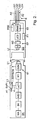
- a control system L is shown, which is connected to a plurality of sensors T1, T2, T3 via corresponding cables K1, K2, K3.
- the sensors T1, T2, T3 are each associated with corresponding measuring points M1, M2, M3.
- the communication between the sensor and the control system takes place via a serial data communication with a "physical layer" according to the RS 485 standard.
- actuators are connected.
- the control system L can be a PLC unit (programmable logic controller) or a decentralized controller DCS (distributed control system).
- the control system L is also connected to a local network (Ethernet), which enables system / company-wide data exchange.
- a block diagram of a sensor according to the invention is shown, which consists of two components, a sensor head SK and a sensor head counterpart SG. These two components are connected to each other via an easy-to-solve bayonet fitting.
- the sensor head SK consists essentially of a sensor MA, which is used to detect a physical quantity z. As pH, temperature, etc. is used.
- the sensor MA is followed by an analog signal processing unit SV, in which the analog measurement signal preprocessed z. B. filtered or amplified.
- an analog / digital converter A / D 1 the measurement signal is fed to a microcontroller ⁇ C1, in which further processing of the measurement signal takes place.
- the microcontroller ⁇ C1 can send and receive data.
- the communication interface S1 consists of a converter W1 and a power supply unit SVSK and a coil L1.
- a sensor head counterpart SG is formed. Both are connected to one another via a bayonet connection, not shown, easily detachable.
- the sensor head counterpart SG has a counterpart S1, which corresponds to the communication interface S1, the communication interface S2.
- This consists of a coil L2 an amplifier V and a converter W2.
- the converter W2 is connected to a microcontroller ⁇ C2.
- the communication with the control system L is wired via a communication interface S3, the z. B. consists of a RS-485 module.
- the cable K has 4 lines LG1, LG2, LG3, LG4, which are surrounded by a shield AS. Two wires are for communication and two wires for power transmission to Sensor head counterpart SG provided.
- a power supply unit SVE For the power supply of the sensor head counterpart SG is a power supply unit SVE, which is supplied via the lines LG1 and LG2 from the control system L from.
- the data transmission between the two communication interfaces S1 and S2 takes place via an inductive coupling.
- energy is transmitted wirelessly to the sensor head SK via this connection.
- This energy is converted in the power supply unit SVSK and converted into a corresponding supply voltage for the individual components.
- various measurement data, parameterization data and sensor-specific data are transmitted, e.g. Sensor identification with serial number, production date, hardware and software version, measured values with main measurement and secondary measurement (i.d.R temperature), calibration data with offset / slope, date / time, calibration method, sensor state with duration of use under extreme conditions, calibration cycles, auxiliary parameters for condition evaluation,
- Information about the measuring point such as TAG number
- information on the sensor element on the sensor head such as measuring range, initial startup, batch.
- sensor head SK and sensor head counterpart SG are completely galvanically separated. This galvanic separation is particularly advantageous in the pH measurement, but not necessarily required for the present invention.
- the sensor head SK is unscrewed from the sensor head counterpart SG and transported to a laboratory remote from the measuring point M1, where the actual calibration takes place. This can be done automatically and the calibration values for each sensor head are stored uniquely assignable in a database.
- This database can, for. B. also be connected to the local network. Then the sensor head has to be replaced at the measuring point from which it was taken.
- the user has a box B with several sensor heads at his disposal. Such a box B is in Fig. 1 presented very stylized.
- the sensor head SK has an antenna A1 and a connected radio unit F1.
- the radio unit F1 can either be connected to the microcontroller ⁇ C1 via the connection line VL or in one alternative embodiment have no connection to the microcontroller ⁇ C1.
- the radio unit F1 corresponds to a transponder, as they are widely used in RFID technology.
- the radio unit F1 is designed to work without external power supply only with the help of the radio energy.
- the radio unit F1 is still connected to the power supply unit SVSK.
- data from a memory provided in the radio unit F1 EEPROM memory with 512 bytes of memory
- a radio unit F2 is provided in the sensor head counterpart SG, which is connected to the microcontroller ⁇ C2.
- the antenna A2 of the radio unit F2 is provided in the cable K outside the shield AS.
- the sensor head SK is not connected to the sensor head counterpart.
- the user Before he wants to put on the sensor head SK, using a portable tester PG data from the not yet assembled sensor T1 determine.
- the portable test device PG the identifier of the sensor head SK, which is stored in the memory EEPROM of the radio unit F1 asks.
- the power supply of the radio unit takes place when queried via this radio link (first radio link EF1).
- the identifier is then transmitted to the control system L via a second longer radio link EF2.
- the control system L determines the measuring point for which this sensor head SK is provided.
- measuring point-specific data are transmitted to the test unit PG and displayed at this. These data help the user to insert the correct sensor head SK at the right measuring point, here the measuring point M1.
- the identifier of the sensor head SK is again read by the tester PG as described above. Based on the identifier, the control system L determines the corresponding measuring point M1 for which the sensor head SK is provided. Now the control system L queries the corresponding measuring point M directly via the cable connection, and thus determines the identifier of the sensor head SK actually used at this measuring point M1. If the sensor head SK has been inserted at the correct measuring point, the identifier transferred from the tester PG to the control system L and the identification determined by the control system L must match. If both identifiers match, then a corresponding clear message ("measuring point ok") of the Control system L sent to the tester PG.
- This information is displayed directly to the user at measuring point M1. The user immediately sees that the right sensor head has been used at this measuring point.
- the control system L sends a corresponding error message ("incorrect sensor head") to the test device PG.
- the radio unit F2 is used. Communication now takes place between test device PG and radio unit F2.
- the radio unit F2 requests the identification of the sensor head via the microcontroller ⁇ C2 from the sensor head SK.
- the reading of the identifier from the EEPROM memory of the radio unit F1 is therefore possible because the radio unit F1 can communicate directly with the microcontroller ⁇ C1, which is supplied via the power supply unit SVSK. Since the sensor head SK projects into a metallic container, due to the shielding, no radio energy can be transmitted to the radio unit F1. In this case, the sensor head can also be identified by the user when installed
- the tester according to the invention a pincer-shaped antenna APG, which must be placed around the antenna A2 to allow communication with this exact sensor.
- the invention is suitable not only for the replacement of sensor heads but also for the first time use. In this case, it only has to be ensured that the measuring point with the identifier of the corresponding sensor head is already stored in the control system L.
- the tester PG is designed in principle for two different radio communication methods. On the one hand, the communication with the radio unit F1 according to the RFID technology and on the other with the radio unit F2 or the control system L, for example, according to the ZigBee standard.
- connection via the connecting line VL between the radio unit F1 and microcontroller ⁇ C1 does not exist.
- a unique ID identifier is stored in the radio unit F1 and in the microcontroller ⁇ C1.
- This unique ID identifier can be used to determine the serial number of the sensor head SK and thus retrieve data for the relevant sensor head from a database.
- the database can z. B. stored directly in the tester PG. If this is not the case, alternatively the database query can also be made via the radio link ZFS.
- sensor data z. B. the measured value can also be read directly from the sensor via the radio unit F1 or F2.
- the invention generally relates to communication with a sensor via the first radio link EFS. Two methods are observed here: 1. Communication with the radio unit F1 and supply of the radio unit F1 from the radio field; 2. Communication via a short-range radio (for example, Zigbee, Nanonet, etc.) with the radio unit F2 in the sensor head counterpart SG.
- a short-range radio for example, Zigbee, Nanonet, etc.
- the special case 2.3 corresponds to case 1.3.
- Table 1 Analog / digital converter A / D1 antenna A1, A2 Antenna tester APG First radio link EFS radio unit F1, F2 electric wire K1, K2, K3 Communication interfaces S1, S2, S3 Control System L sensor MA measuring point M1, M2, M3 microcontroller mC1, mC2 sensor head SK Signal processing unit SV Power supply unit SVSG, SVF1, SVSK Kitchen sink L1, L2 Sensor head counterpart SG Portable tester PG sensor T1, T2, T3 amplifier V converter W1, W2 Second radio link ZFS connecting line VL
Landscapes
- Physics & Mathematics (AREA)
- General Physics & Mathematics (AREA)
- Arrangements For Transmission Of Measured Signals (AREA)
Claims (5)
- Capteur destiné à un point de mesure constitué d'une tête de capteur (SK) et d'une contre-tête de capteur (SG) pouvant être reliées entre elles par une liaison amovible, la tête de capteur (SK) comportant un transmetteur de mesure (MA) destiné à l'acquisition de valeurs mesurées, un premier microcontrôleur (µC1) destiné au traitement des valeurs mesurées, une unité d'alimentation en tension (SVSK) destinée à l'alimentation en énergie de la tête de capteur (SK), et une interface de communication (S1) destinée à l'échange de données avec la contre-tête de capteur (SG), la contre-tête de capteur étant reliée avec un système de contrôle-commande, auquel sont transmises les valeurs mesurées traitées, caractérisé
en ce que le premier microcontrôleur (µC1) est relié avec une unité radio (F1), qui est raccordée à l'unité d'alimentation en tension (SVSK) de la tête de capteur et qui présente une unité d'alimentation en tension (SVF1) séparée supplémentaire et un accumulateur, l'unité d'alimentation en tension (SVF1) séparée supplémentaire étant alimentée via l'énergie radio, permettant ainsi un échange de données sans fil, même lorsque l'unité d'alimentation en tension (SVSK) ne fournit aucune énergie pour la tête de capteur (SK). - Capteur selon la revendication 1, caractérisé en ce que l'échange de données entre la tête de capteur (SK) et la contre-tête de capteur (SG) s'effectue sans fil et en ce que l'alimentation en énergie de l'unité d'alimentation en tension (SVSK) de la tête de capteur (SK) s'effectue également sans fil.
- Capteur destiné à un point de mesure, selon l'une des revendications précédentes, la contre-tête de capteur (SG) comportant une interface de communication (S2) destinée à la communication de données et/ou à la transmission de l'énergie avec la tête de capteur (SK), un microcontrôleur (µC2) et une interface de communication (S2) destinée à la transmission de données vers le système numérique de contrôle-commande (L), caractérisé en ce que le microcontrôleur (µC2) est relié avec une unité radio (F2).
- Procédé pour le contrôle d'un capteur destiné à un point de mesure comportant une tête de capteur (SK) et une contre-tête de capteur (SG), qui sont reliées entre elles de façon amovible par l'intermédiaire d'une connexion enfichable, la contre-tête de capteur (SG) étant raccordée via une connexion par câble (K) au système numérique de contrôle-commande (L), lequel procédé comporte les étapes suivantes :1. Lecture d'un code d'identification de la tête de capteur (SK) dans un appareil de contrôle (PG) portable par l'intermédiaire d'une liaison radio (EFS) ;2. Transmission du code d'identification de l'appareil de contrôle (PG) au système numérique de contrôle commande par l'intermédiaire d'une deuxième liaison radio (ZFS) ;3. Transmission de données spécifiques aux points de mesure du système numérique de contrôle commande (L) à l'appareil de contrôle ;4. Affichage des données spécifiques aux points de mesure sur l'appareil de contrôle (PG).
- Procédé selon la revendication 4, pour lequel la tête de capteur (SK) et la contre-tête de capteur (SG) sont reliées, lequel procédé comporte les étapes suivantes :5. Interrogation par le système numérique de contrôle commande (L) du code d'identification du point de mesure (M1) affecté à la tête de capteur (SK) ;6. Si les deux codes coïncident, un message clair est transmis en tant que donnée spécifique au point de mesure, depuis le système numérique de contrôle commande (L) à l'appareil de contrôle (PG) ;7. Si les deux codes ne coïncident pas, un message d'erreur correspondant est transmis en tant qu'information spécifique au point de mesure.
Priority Applications (1)
| Application Number | Priority Date | Filing Date | Title |
|---|---|---|---|
| EP16164108.9A EP3091340A1 (fr) | 2006-04-26 | 2007-04-13 | Capteur pour un point de mesure et procédé de contrôle d'un capteur pour un point de mesure |
Applications Claiming Priority (4)
| Application Number | Priority Date | Filing Date | Title |
|---|---|---|---|
| DE102006020016 | 2006-04-26 | ||
| DE200610020341 DE102006020341A1 (de) | 2006-04-28 | 2006-04-28 | Sensor für eine Messstelle und Verfahren zur Überprüfung eines Sensors für eine Messstelle |
| DE102006028826 | 2006-06-21 | ||
| PCT/EP2007/053609 WO2007125020A1 (fr) | 2006-04-26 | 2007-04-13 | Capteur pour un point de mesure et procédé de contrôle d'un capteur pour un point de mesure |
Related Child Applications (2)
| Application Number | Title | Priority Date | Filing Date |
|---|---|---|---|
| EP16164108.9A Division EP3091340A1 (fr) | 2006-04-26 | 2007-04-13 | Capteur pour un point de mesure et procédé de contrôle d'un capteur pour un point de mesure |
| EP16164108.9A Division-Into EP3091340A1 (fr) | 2006-04-26 | 2007-04-13 | Capteur pour un point de mesure et procédé de contrôle d'un capteur pour un point de mesure |
Publications (2)
| Publication Number | Publication Date |
|---|---|
| EP2010867A1 EP2010867A1 (fr) | 2009-01-07 |
| EP2010867B1 true EP2010867B1 (fr) | 2017-05-31 |
Family
ID=38512188
Family Applications (2)
| Application Number | Title | Priority Date | Filing Date |
|---|---|---|---|
| EP16164108.9A Withdrawn EP3091340A1 (fr) | 2006-04-26 | 2007-04-13 | Capteur pour un point de mesure et procédé de contrôle d'un capteur pour un point de mesure |
| EP07728076.6A Not-in-force EP2010867B1 (fr) | 2006-04-26 | 2007-04-13 | Capteur pour un point de mesure et procédé de contrôle d'un capteur pour un point de mesure |
Family Applications Before (1)
| Application Number | Title | Priority Date | Filing Date |
|---|---|---|---|
| EP16164108.9A Withdrawn EP3091340A1 (fr) | 2006-04-26 | 2007-04-13 | Capteur pour un point de mesure et procédé de contrôle d'un capteur pour un point de mesure |
Country Status (4)
| Country | Link |
|---|---|
| US (2) | US8285518B2 (fr) |
| EP (2) | EP3091340A1 (fr) |
| CN (1) | CN101432595B (fr) |
| WO (1) | WO2007125020A1 (fr) |
Cited By (1)
| Publication number | Priority date | Publication date | Assignee | Title |
|---|---|---|---|---|
| EP4571436A1 (fr) * | 2023-12-13 | 2025-06-18 | Siemens Aktiengesellschaft | Validation d'une position prévue pour un capteur |
Families Citing this family (9)
| Publication number | Priority date | Publication date | Assignee | Title |
|---|---|---|---|---|
| US20170090002A9 (en) * | 2006-04-26 | 2017-03-30 | Endress + Hauser Conducta Gesellschaft Fur Mess - Und Regeltechnik Mbh + Co. Kg | Sensor for a Measuring Point and Method for Testing a Sensor for a Measuring Point |
| DE102007053223A1 (de) * | 2007-11-06 | 2009-05-07 | Endress + Hauser Conducta Gesellschaft für Mess- und Regeltechnik mbH + Co. KG | Verfahren zum Betreiben einer Messstelle, Messstelle und Sensoreinheit für eine solche Messstelle |
| DE102012109680A1 (de) | 2012-10-11 | 2014-05-15 | Endress + Hauser Gmbh + Co. Kg | Vorrichtung und System zur Bestimmung, Optimierung oder Überwachung zumindest einer Prozessgröße |
| DE102013111714B8 (de) | 2013-10-24 | 2024-10-02 | Endress+Hauser Conducta Gmbh+Co. Kg | Verfahren zur Funktionseinstellung einer Messstelle |
| TWI651621B (zh) * | 2013-12-18 | 2019-02-21 | 財團法人國家實驗研究院 | 具有可重組模組化感測裝置的感測系統及該感測系統的初始方法 |
| DE102014015129A1 (de) * | 2014-10-14 | 2016-04-14 | Wabco Gmbh | Verfahren zur Identifikation einer Sensorvorrichtung zur Drehzahlmessung, Sensorvorrichtung zur Drehzahlmessung und Fahrzeug mit wenigstens einer Sensorvorrichtung zur Drehzahlmessung |
| DE102017128741A1 (de) * | 2017-12-04 | 2019-06-06 | Endress+Hauser Conducta Gmbh+Co. Kg | Sensoranschlusselement für einen Sensor und Sensorsystem |
| PL4130686T3 (pl) | 2018-10-15 | 2025-07-21 | Refco Manufacturing Ltd. | Sposób przeprowadzania zadań pomiarowych i zarządzania danymi pomiarowymi |
| DE102018132384B4 (de) * | 2018-12-17 | 2025-11-06 | Endress+Hauser Conducta Gmbh+Co. Kg | Hardware-Software-Kommunikationssystem für eine Sensorsignalüberwachung der Prozessautomatisierungstechnik |
Citations (1)
| Publication number | Priority date | Publication date | Assignee | Title |
|---|---|---|---|---|
| DE10313639A1 (de) * | 2003-03-26 | 2004-10-07 | Endress + Hauser Conducta Gesellschaft für Mess- und Regeltechnik mbH + Co. KG | Elektrochemischer Gassensor |
Family Cites Families (13)
| Publication number | Priority date | Publication date | Assignee | Title |
|---|---|---|---|---|
| US5597534A (en) * | 1994-07-05 | 1997-01-28 | Texas Instruments Deutschland Gmbh | Apparatus for wireless chemical sensing |
| DE19722744A1 (de) | 1997-05-30 | 1998-12-03 | Draegerwerk Ag | Detektionssystem mit austauschbaren Sensoren |
| DE19849293A1 (de) | 1998-10-26 | 2000-04-27 | Ibtl Ing Buero Lang & Partner | Vorrichtung und Verfahren zum Erfassen von Meßwerten an einer Viehlzahl von Meßstellen eines Meßobjekts |
| US6720866B1 (en) * | 1999-03-30 | 2004-04-13 | Microchip Technology Incorporated | Radio frequency identification tag device with sensor input |
| US6182497B1 (en) * | 1999-08-20 | 2001-02-06 | Neodym Systems Inc | Gas detection system and method |
| US6294997B1 (en) * | 1999-10-04 | 2001-09-25 | Intermec Ip Corp. | RFID tag having timing and environment modules |
| DE10032864B4 (de) | 2000-07-06 | 2004-03-04 | Abb Research Ltd. | Näherungssensor-Adapter |
| DE10064812A1 (de) * | 2000-12-22 | 2002-06-27 | Endress & Hauser Gmbh & Co Kg | Vorrichtung zum Aussenden hochfrequenter Signale |
| DE20107113U1 (de) | 2001-04-25 | 2001-07-05 | Abb Patent Gmbh, 68309 Mannheim | Einrichtung zur Energieversorgung von Feldgeräten |
| DE10241241B4 (de) | 2002-09-06 | 2004-08-05 | Abb Research Ltd. | Verfahren zur Messgrößenerfassung eines Erfassungsgerätes |
| DE10305986B4 (de) * | 2003-02-12 | 2022-07-21 | IAD Gesellschaft für Informatik, Automatisierung und Datenverarbeitung mbH | Messsystem mit intelligentem Sensorkopf für Mittel- oder Hochspannungsanlagen oder im Bergbau |
| EP1636579A4 (fr) * | 2003-06-10 | 2011-10-05 | Smiths Detection Inc | Ensemble detecteur |
| DE10344262A1 (de) | 2003-09-23 | 2005-04-14 | Endress + Hauser Conducta Gesellschaft für Mess- und Regeltechnik mbH + Co. KG | Steckmodul für einen Flüssigkeits- oder Gassensor |
-
2007
- 2007-04-13 WO PCT/EP2007/053609 patent/WO2007125020A1/fr not_active Ceased
- 2007-04-13 EP EP16164108.9A patent/EP3091340A1/fr not_active Withdrawn
- 2007-04-13 US US12/226,621 patent/US8285518B2/en active Active
- 2007-04-13 EP EP07728076.6A patent/EP2010867B1/fr not_active Not-in-force
- 2007-04-13 CN CN2007800151033A patent/CN101432595B/zh not_active Expired - Fee Related
-
2012
- 2012-09-13 US US13/613,114 patent/US8606546B2/en not_active Expired - Fee Related
Patent Citations (1)
| Publication number | Priority date | Publication date | Assignee | Title |
|---|---|---|---|---|
| DE10313639A1 (de) * | 2003-03-26 | 2004-10-07 | Endress + Hauser Conducta Gesellschaft für Mess- und Regeltechnik mbH + Co. KG | Elektrochemischer Gassensor |
Cited By (1)
| Publication number | Priority date | Publication date | Assignee | Title |
|---|---|---|---|---|
| EP4571436A1 (fr) * | 2023-12-13 | 2025-06-18 | Siemens Aktiengesellschaft | Validation d'une position prévue pour un capteur |
Also Published As
| Publication number | Publication date |
|---|---|
| US20130013258A1 (en) | 2013-01-10 |
| WO2007125020A1 (fr) | 2007-11-08 |
| US8606546B2 (en) | 2013-12-10 |
| EP3091340A1 (fr) | 2016-11-09 |
| EP2010867A1 (fr) | 2009-01-07 |
| CN101432595B (zh) | 2011-05-18 |
| CN101432595A (zh) | 2009-05-13 |
| US8285518B2 (en) | 2012-10-09 |
| US20090299700A1 (en) | 2009-12-03 |
Similar Documents
| Publication | Publication Date | Title |
|---|---|---|
| EP2010867B1 (fr) | Capteur pour un point de mesure et procédé de contrôle d'un capteur pour un point de mesure | |
| DE102013111714A1 (de) | Verfahren zur Funktionseinstellung einer Messstelle und Messstelle | |
| DE102013013299A1 (de) | Verfahren zum Bedienen eines Feldgeräts | |
| DE102009045386A1 (de) | Verfahren zum Betreiben eines Feldbus-Interface | |
| DE102008038415A1 (de) | Verfahren zur Überwachung des Ladezustands bzw. der Restkapazität einer Batterie bzw. eines Akkus in der Automatisierungstechnik | |
| DE102007059671A1 (de) | Verfahren zum Betreiben eines Systems aufweisend ein Feldgerät und ein Bediensystem | |
| WO2014095256A1 (fr) | Appareil de terrain et procédé de lecture de données à partir d'un appareil de terrain inactif ou défectueux | |
| DE102012107673A1 (de) | Verfahren zum Feldgerätetausch mit Hilfe eines mobilen Endgerätes | |
| WO2007124834A2 (fr) | Procédé d'étalonnage et/ou de réglage d'un capteur, notamment d'un capteur électrochimique, électrophysique ou optique, ainsi que capteur correspondant | |
| WO2010049408A1 (fr) | Appareil de mesure modulaire à répartition de données et d'algorithmes | |
| DE102006020341A1 (de) | Sensor für eine Messstelle und Verfahren zur Überprüfung eines Sensors für eine Messstelle | |
| DE102010062657A1 (de) | Bereitstellung von Kalibrierungsdaten zu Messeinrichtungen | |
| EP3125053B1 (fr) | Procede et composant peripherique destines a la transmission de variables hart et unite centrale destinee a lire les variables hart | |
| DE102008042919A1 (de) | Feldgerät der Prozessautomatisierungstechnik | |
| DE102018118872A1 (de) | Verfahren zur Überprüfung der Datenübertragung eines elektronischen Schaltgerätes | |
| WO2012028366A1 (fr) | Procédé garantissant le mode de fonctionnement correct d'une installation d'automatisation | |
| DE102016122051A1 (de) | Verfahren und System zum Ermitteln von Diagnoseinformationen von zumindest einem Feldgerät der Prozessautomatisierung | |
| WO2025040295A1 (fr) | Procédé et système de mise en service, de fonctionnement et/ou de maintien d'un point de mesure dans un système de technologie d'automatisation | |
| DE102007052125A1 (de) | Prüfsystem für einen Baugruppenträger, Baugruppenträger mit einem Prüfsystem sowie Verfahren zum Prüfen eines Baugruppenträgers | |
| WO2005029293A1 (fr) | Unite d'entree destinee a la technique d'automatisation des processus | |
| EP1800193A1 (fr) | Procede d'exploitation d'un appareil de champ, de structure modulaire, relevant de la technique de l'automatisation | |
| EP2010898B1 (fr) | Contenant de transport pour plusieurs capteurs potentiométriques | |
| DE102017115517A1 (de) | Verfahren und Datenumsetzungseinheit zum Überwachen einer Anlage der Automatisierungstechnik | |
| DE102010003741A1 (de) | Verfahren zum Datenaustausch | |
| DE102023136446A1 (de) | Verfahren zum Erstellen eines Geräteberichts eines Feldgeräts sowie System zum Erstellen eines Geräteberichts eines Feldgeräts |
Legal Events
| Date | Code | Title | Description |
|---|---|---|---|
| PUAI | Public reference made under article 153(3) epc to a published international application that has entered the european phase |
Free format text: ORIGINAL CODE: 0009012 |
|
| 17P | Request for examination filed |
Effective date: 20081021 |
|
| AK | Designated contracting states |
Kind code of ref document: A1 Designated state(s): AT BE BG CH CY CZ DE DK EE ES FI FR GB GR HU IE IS IT LI LT LU LV MC MT NL PL PT RO SE SI SK TR |
|
| AX | Request for extension of the european patent |
Extension state: AL BA HR MK RS |
|
| 17Q | First examination report despatched |
Effective date: 20120314 |
|
| DAX | Request for extension of the european patent (deleted) | ||
| RAP1 | Party data changed (applicant data changed or rights of an application transferred) |
Owner name: ENDRESS + HAUSER CONDUCTA GMBH+CO. KG |
|
| REG | Reference to a national code |
Ref country code: DE Ref legal event code: R079 Ref document number: 502007015669 Country of ref document: DE Free format text: PREVIOUS MAIN CLASS: G01D0005480000 Ipc: G01D0021000000 |
|
| RIC1 | Information provided on ipc code assigned before grant |
Ipc: H03K 17/95 20060101ALI20161025BHEP Ipc: G01D 5/48 20060101ALI20161025BHEP Ipc: G01D 21/00 20060101AFI20161025BHEP |
|
| GRAP | Despatch of communication of intention to grant a patent |
Free format text: ORIGINAL CODE: EPIDOSNIGR1 |
|
| STAA | Information on the status of an ep patent application or granted ep patent |
Free format text: STATUS: GRANT OF PATENT IS INTENDED |
|
| INTG | Intention to grant announced |
Effective date: 20161222 |
|
| GRAS | Grant fee paid |
Free format text: ORIGINAL CODE: EPIDOSNIGR3 |
|
| GRAA | (expected) grant |
Free format text: ORIGINAL CODE: 0009210 |
|
| STAA | Information on the status of an ep patent application or granted ep patent |
Free format text: STATUS: THE PATENT HAS BEEN GRANTED |
|
| AK | Designated contracting states |
Kind code of ref document: B1 Designated state(s): AT BE BG CH CY CZ DE DK EE ES FI FR GB GR HU IE IS IT LI LT LU LV MC MT NL PL PT RO SE SI SK TR |
|
| REG | Reference to a national code |
Ref country code: CH Ref legal event code: EP Ref country code: GB Ref legal event code: FG4D Free format text: NOT ENGLISH |
|
| REG | Reference to a national code |
Ref country code: AT Ref legal event code: REF Ref document number: 897907 Country of ref document: AT Kind code of ref document: T Effective date: 20170615 |
|
| REG | Reference to a national code |
Ref country code: IE Ref legal event code: FG4D Free format text: LANGUAGE OF EP DOCUMENT: GERMAN |
|
| REG | Reference to a national code |
Ref country code: DE Ref legal event code: R096 Ref document number: 502007015669 Country of ref document: DE |
|
| REG | Reference to a national code |
Ref country code: NL Ref legal event code: MP Effective date: 20170531 |
|
| REG | Reference to a national code |
Ref country code: LT Ref legal event code: MG4D |
|
| PG25 | Lapsed in a contracting state [announced via postgrant information from national office to epo] |
Ref country code: ES Free format text: LAPSE BECAUSE OF FAILURE TO SUBMIT A TRANSLATION OF THE DESCRIPTION OR TO PAY THE FEE WITHIN THE PRESCRIBED TIME-LIMIT Effective date: 20170531 Ref country code: LT Free format text: LAPSE BECAUSE OF FAILURE TO SUBMIT A TRANSLATION OF THE DESCRIPTION OR TO PAY THE FEE WITHIN THE PRESCRIBED TIME-LIMIT Effective date: 20170531 Ref country code: FI Free format text: LAPSE BECAUSE OF FAILURE TO SUBMIT A TRANSLATION OF THE DESCRIPTION OR TO PAY THE FEE WITHIN THE PRESCRIBED TIME-LIMIT Effective date: 20170531 Ref country code: GR Free format text: LAPSE BECAUSE OF FAILURE TO SUBMIT A TRANSLATION OF THE DESCRIPTION OR TO PAY THE FEE WITHIN THE PRESCRIBED TIME-LIMIT Effective date: 20170901 |
|
| PG25 | Lapsed in a contracting state [announced via postgrant information from national office to epo] |
Ref country code: SE Free format text: LAPSE BECAUSE OF FAILURE TO SUBMIT A TRANSLATION OF THE DESCRIPTION OR TO PAY THE FEE WITHIN THE PRESCRIBED TIME-LIMIT Effective date: 20170531 Ref country code: LV Free format text: LAPSE BECAUSE OF FAILURE TO SUBMIT A TRANSLATION OF THE DESCRIPTION OR TO PAY THE FEE WITHIN THE PRESCRIBED TIME-LIMIT Effective date: 20170531 Ref country code: BG Free format text: LAPSE BECAUSE OF FAILURE TO SUBMIT A TRANSLATION OF THE DESCRIPTION OR TO PAY THE FEE WITHIN THE PRESCRIBED TIME-LIMIT Effective date: 20170831 Ref country code: IS Free format text: LAPSE BECAUSE OF FAILURE TO SUBMIT A TRANSLATION OF THE DESCRIPTION OR TO PAY THE FEE WITHIN THE PRESCRIBED TIME-LIMIT Effective date: 20170930 Ref country code: NL Free format text: LAPSE BECAUSE OF FAILURE TO SUBMIT A TRANSLATION OF THE DESCRIPTION OR TO PAY THE FEE WITHIN THE PRESCRIBED TIME-LIMIT Effective date: 20170531 |
|
| PG25 | Lapsed in a contracting state [announced via postgrant information from national office to epo] |
Ref country code: RO Free format text: LAPSE BECAUSE OF FAILURE TO SUBMIT A TRANSLATION OF THE DESCRIPTION OR TO PAY THE FEE WITHIN THE PRESCRIBED TIME-LIMIT Effective date: 20170531 Ref country code: CZ Free format text: LAPSE BECAUSE OF FAILURE TO SUBMIT A TRANSLATION OF THE DESCRIPTION OR TO PAY THE FEE WITHIN THE PRESCRIBED TIME-LIMIT Effective date: 20170531 Ref country code: SK Free format text: LAPSE BECAUSE OF FAILURE TO SUBMIT A TRANSLATION OF THE DESCRIPTION OR TO PAY THE FEE WITHIN THE PRESCRIBED TIME-LIMIT Effective date: 20170531 Ref country code: DK Free format text: LAPSE BECAUSE OF FAILURE TO SUBMIT A TRANSLATION OF THE DESCRIPTION OR TO PAY THE FEE WITHIN THE PRESCRIBED TIME-LIMIT Effective date: 20170531 Ref country code: EE Free format text: LAPSE BECAUSE OF FAILURE TO SUBMIT A TRANSLATION OF THE DESCRIPTION OR TO PAY THE FEE WITHIN THE PRESCRIBED TIME-LIMIT Effective date: 20170531 |
|
| PG25 | Lapsed in a contracting state [announced via postgrant information from national office to epo] |
Ref country code: PL Free format text: LAPSE BECAUSE OF FAILURE TO SUBMIT A TRANSLATION OF THE DESCRIPTION OR TO PAY THE FEE WITHIN THE PRESCRIBED TIME-LIMIT Effective date: 20170531 Ref country code: IT Free format text: LAPSE BECAUSE OF FAILURE TO SUBMIT A TRANSLATION OF THE DESCRIPTION OR TO PAY THE FEE WITHIN THE PRESCRIBED TIME-LIMIT Effective date: 20170531 |
|
| REG | Reference to a national code |
Ref country code: DE Ref legal event code: R097 Ref document number: 502007015669 Country of ref document: DE |
|
| PLBE | No opposition filed within time limit |
Free format text: ORIGINAL CODE: 0009261 |
|
| STAA | Information on the status of an ep patent application or granted ep patent |
Free format text: STATUS: NO OPPOSITION FILED WITHIN TIME LIMIT |
|
| 26N | No opposition filed |
Effective date: 20180301 |
|
| PG25 | Lapsed in a contracting state [announced via postgrant information from national office to epo] |
Ref country code: SI Free format text: LAPSE BECAUSE OF FAILURE TO SUBMIT A TRANSLATION OF THE DESCRIPTION OR TO PAY THE FEE WITHIN THE PRESCRIBED TIME-LIMIT Effective date: 20170531 |
|
| PG25 | Lapsed in a contracting state [announced via postgrant information from national office to epo] |
Ref country code: MT Free format text: LAPSE BECAUSE OF FAILURE TO SUBMIT A TRANSLATION OF THE DESCRIPTION OR TO PAY THE FEE WITHIN THE PRESCRIBED TIME-LIMIT Effective date: 20170531 |
|
| PG25 | Lapsed in a contracting state [announced via postgrant information from national office to epo] |
Ref country code: MC Free format text: LAPSE BECAUSE OF FAILURE TO SUBMIT A TRANSLATION OF THE DESCRIPTION OR TO PAY THE FEE WITHIN THE PRESCRIBED TIME-LIMIT Effective date: 20170531 |
|
| REG | Reference to a national code |
Ref country code: BE Ref legal event code: MM Effective date: 20180430 |
|
| GBPC | Gb: european patent ceased through non-payment of renewal fee |
Effective date: 20180413 |
|
| REG | Reference to a national code |
Ref country code: IE Ref legal event code: MM4A |
|
| PG25 | Lapsed in a contracting state [announced via postgrant information from national office to epo] |
Ref country code: LU Free format text: LAPSE BECAUSE OF NON-PAYMENT OF DUE FEES Effective date: 20180413 |
|
| PG25 | Lapsed in a contracting state [announced via postgrant information from national office to epo] |
Ref country code: GB Free format text: LAPSE BECAUSE OF NON-PAYMENT OF DUE FEES Effective date: 20180413 Ref country code: BE Free format text: LAPSE BECAUSE OF NON-PAYMENT OF DUE FEES Effective date: 20180430 |
|
| PG25 | Lapsed in a contracting state [announced via postgrant information from national office to epo] |
Ref country code: IE Free format text: LAPSE BECAUSE OF NON-PAYMENT OF DUE FEES Effective date: 20180413 Ref country code: FR Free format text: LAPSE BECAUSE OF NON-PAYMENT OF DUE FEES Effective date: 20180430 |
|
| REG | Reference to a national code |
Ref country code: AT Ref legal event code: MM01 Ref document number: 897907 Country of ref document: AT Kind code of ref document: T Effective date: 20180413 |
|
| PG25 | Lapsed in a contracting state [announced via postgrant information from national office to epo] |
Ref country code: AT Free format text: LAPSE BECAUSE OF NON-PAYMENT OF DUE FEES Effective date: 20180413 |
|
| PG25 | Lapsed in a contracting state [announced via postgrant information from national office to epo] |
Ref country code: TR Free format text: LAPSE BECAUSE OF FAILURE TO SUBMIT A TRANSLATION OF THE DESCRIPTION OR TO PAY THE FEE WITHIN THE PRESCRIBED TIME-LIMIT Effective date: 20170531 |
|
| PG25 | Lapsed in a contracting state [announced via postgrant information from national office to epo] |
Ref country code: HU Free format text: LAPSE BECAUSE OF FAILURE TO SUBMIT A TRANSLATION OF THE DESCRIPTION OR TO PAY THE FEE WITHIN THE PRESCRIBED TIME-LIMIT; INVALID AB INITIO Effective date: 20070413 Ref country code: PT Free format text: LAPSE BECAUSE OF FAILURE TO SUBMIT A TRANSLATION OF THE DESCRIPTION OR TO PAY THE FEE WITHIN THE PRESCRIBED TIME-LIMIT Effective date: 20170531 |
|
| PG25 | Lapsed in a contracting state [announced via postgrant information from national office to epo] |
Ref country code: CY Free format text: LAPSE BECAUSE OF FAILURE TO SUBMIT A TRANSLATION OF THE DESCRIPTION OR TO PAY THE FEE WITHIN THE PRESCRIBED TIME-LIMIT Effective date: 20170531 |
|
| PGFP | Annual fee paid to national office [announced via postgrant information from national office to epo] |
Ref country code: CH Payment date: 20220421 Year of fee payment: 16 |
|
| P01 | Opt-out of the competence of the unified patent court (upc) registered |
Effective date: 20230601 |
|
| PGFP | Annual fee paid to national office [announced via postgrant information from national office to epo] |
Ref country code: DE Payment date: 20230420 Year of fee payment: 17 |
|
| REG | Reference to a national code |
Ref country code: CH Ref legal event code: PL |
|
| PG25 | Lapsed in a contracting state [announced via postgrant information from national office to epo] |
Ref country code: LI Free format text: LAPSE BECAUSE OF NON-PAYMENT OF DUE FEES Effective date: 20230430 Ref country code: CH Free format text: LAPSE BECAUSE OF NON-PAYMENT OF DUE FEES Effective date: 20230430 |
|
| REG | Reference to a national code |
Ref country code: DE Ref legal event code: R119 Ref document number: 502007015669 Country of ref document: DE |
|
| PG25 | Lapsed in a contracting state [announced via postgrant information from national office to epo] |
Ref country code: DE Free format text: LAPSE BECAUSE OF NON-PAYMENT OF DUE FEES Effective date: 20241105 |
|
| PG25 | Lapsed in a contracting state [announced via postgrant information from national office to epo] |
Ref country code: DE Free format text: LAPSE BECAUSE OF NON-PAYMENT OF DUE FEES Effective date: 20241105 |