EP2010883B1 - Composant de jonction présentant un élément détecteur thermorésistant - Google Patents
Composant de jonction présentant un élément détecteur thermorésistant Download PDFInfo
- Publication number
- EP2010883B1 EP2010883B1 EP07724667.6A EP07724667A EP2010883B1 EP 2010883 B1 EP2010883 B1 EP 2010883B1 EP 07724667 A EP07724667 A EP 07724667A EP 2010883 B1 EP2010883 B1 EP 2010883B1
- Authority
- EP
- European Patent Office
- Prior art keywords
- layer
- connector component
- component according
- ultrasonic sensor
- ultrasonic
- Prior art date
- Legal status (The legal status is an assumption and is not a legal conclusion. Google has not performed a legal analysis and makes no representation as to the accuracy of the status listed.)
- Active
Links
Images


Classifications
-
- G—PHYSICS
- G01—MEASURING; TESTING
- G01L—MEASURING FORCE, STRESS, TORQUE, WORK, MECHANICAL POWER, MECHANICAL EFFICIENCY, OR FLUID PRESSURE
- G01L5/00—Apparatus for, or methods of, measuring force, work, mechanical power, or torque, specially adapted for specific purposes
- G01L5/24—Apparatus for, or methods of, measuring force, work, mechanical power, or torque, specially adapted for specific purposes for determining value of torque or twisting moment for tightening a nut or other member which is similarly stressed
- G01L5/246—Apparatus for, or methods of, measuring force, work, mechanical power, or torque, specially adapted for specific purposes for determining value of torque or twisting moment for tightening a nut or other member which is similarly stressed using acoustic waves
-
- F—MECHANICAL ENGINEERING; LIGHTING; HEATING; WEAPONS; BLASTING
- F16—ENGINEERING ELEMENTS AND UNITS; GENERAL MEASURES FOR PRODUCING AND MAINTAINING EFFECTIVE FUNCTIONING OF MACHINES OR INSTALLATIONS; THERMAL INSULATION IN GENERAL
- F16B—DEVICES FOR FASTENING OR SECURING CONSTRUCTIONAL ELEMENTS OR MACHINE PARTS TOGETHER, e.g. NAILS, BOLTS, CIRCLIPS, CLAMPS, CLIPS OR WEDGES; JOINTS OR JOINTING
- F16B31/00—Screwed connections specially modified in view of tensile load; Break-bolts
- F16B31/02—Screwed connections specially modified in view of tensile load; Break-bolts for indicating the attainment of a particular tensile load or limiting tensile load
- F16B31/025—Screwed connections specially modified in view of tensile load; Break-bolts for indicating the attainment of a particular tensile load or limiting tensile load with a gauge pin in a longitudinal bore in the body of the bolt
-
- G—PHYSICS
- G01—MEASURING; TESTING
- G01L—MEASURING FORCE, STRESS, TORQUE, WORK, MECHANICAL POWER, MECHANICAL EFFICIENCY, OR FLUID PRESSURE
- G01L5/00—Apparatus for, or methods of, measuring force, work, mechanical power, or torque, specially adapted for specific purposes
- G01L5/0004—Force transducers adapted for mounting in a bore of the force receiving structure
Definitions
- connection components such. As screws or bolts are checked by means of ultrasound measuring method on their biasing force or their clamping force out. For this purpose, the signal propagation time of ultrasonic waves, which are coupled into the respective connection component with one or more separate, frequently predefined operating frequencies, is measured.
- connection components such as bolts or screws can be manufactured
- the material properties make higher demands on a measuring method for determining the biasing force.
- a frequency-modulated chirp signal x (t) is provided for driving an ultrasonic transducer arranged in a transmission path whose instantaneous frequency f is not linearly modulated with time t.
- the time profile f (t) of the instantaneous frequency of the frequency-modulated chirp signal x (t) to a transfer function H (f) is adapted to the predetermined transmission path.
- the temporal change of the instantaneous frequency f of the frequency-modulated chirp signal x (t) is correlated with the value of the transmission function H (f) of the transmission path belonging to this frequency f such that at frequencies f with a low associated value of the transfer function H (f) the speed of the frequency change is smaller than at frequencies f with a high associated value of the transfer function H (f).
- a device for ultrasonic testing with a signal generator for driving an ultrasonic transducer with a frequency-modulated chirp signal x (t) is proposed, whose instantaneous frequency f is not linearly dependent on time, and a pulse compression filter for converting the chirp received from this or another ultrasonic transducer Signal y (t) into a short received pulse z (t).
- a method for determining the biasing force of connecting members by ultrasonic excitation is known.
- the clamping force of connecting components for.
- screws or bolts measured by broadband ultrasonic excitation.
- a pulse generator is used, which generates an ultrasonic pulse by means of statistically distributed phase position of used and / or resolvable frequency components with a predefinable pulse width.
- the pulse width is adapted to intervals of ultrasonic pulse echoes such that no overlap of individual different reflections occurs and the maximum possible pulse duration is achieved.
- the received ultrasound pulse echo is temporally selected with respect to at least one reflex and subjected to a transformation process, such that for a defined time related to the ultrasound all frequency contributions are shifted in time or in phase.
- connection component in the head region of which there is an ultrasound transducer, the structure of which is designed as a layer structure.
- ultrasonic transducer which are also referred to as ultrasonic sensors come today z. B. glued sensors with PVDF films for use.
- the ultrasonic sensors with PVDF films are very sensitive and are used, for. B. applied to screw heads designed as screws connecting components.
- the application and fixing to a screw head is usually done via an adhesive layer.
- PVDF films have the disadvantage that they are not temperature resistant. From a temperature of approx. 70 ° C, an aging process occurs in the PVDF film, which in extreme cases can lead to the dissolution of the PVDF film.
- the fundamental problem with PVDF films is the resolution of the film seen over the operating time or a partial separation of the film material.
- a load-indicating connecting element is known in which the load is measured by means of ultrasound.
- two electrodes are applied to the connecting element, wherein a film having piezoelectric properties is formed on one of the electrodes by means of a vapor deposition process.
- the present invention seeks to provide a connection component with integrated ultrasonic sensor available, which in particular at higher temperatures of> 350 ° C is operational and remains stable over a long period of operation.
- the ultrasonic sensor should be formed resistant to oxidation.
- a connecting element which is in particular helically designed which comprises an ultrasound sensor having a layer structure at a freely accessible end.
- the ultrasonic sensor is a component of the helically shaped connecting component and is in particular on a End face on the screw head and this opposite freely accessible end of the screw, ie an end face of the connecting member after the thread outlet assigned. Both the end face representing the screw head and the end opposite the screw represent a freely accessible point at which an ultrasonic signal can be coupled into the connection component.
- the ultrasonic sensor preferably comprises at least one electrode layer, individual electrodes being insulated from one another.
- the layer structure of the proposed connection component with integrated ultrasonic sensor comprises a mechanical protective layer as well as a layer of material having piezoelectric properties.
- the said at least three layers of the layer structure of the ultrasonic sensor are applied to the freely accessible end of the preferably helically shaped connecting component in sputtering technique.
- the connecting member is preferably made of common screw materials, such.
- high-alloy steels special steels, titanium and its alloys, such.
- TiAl6V4 aluminum and its alloys, brass, Inconel (nickel alloy) and non-magnetic steels, such. B. A286 steel.
- the layer structure of the at least three-layer ultrasound sensor has, executed in thin film technology, on one of the respective freely accessible end faces applied individual layers, wherein the respective freely accessible end face of the connecting member is sputtered with the piezoelectric properties having material.
- connection components with integrated ultrasonic sensor are characterized by a high temperature resistance over a long period of operation. They are for use z. B. at extremely high temperatures having aircraft engines, especially in the vicinity of the combustion chamber, suitable, where there is a heating of the connecting member is reached to a temperature level between 350 ° C and 400 ° C. At an assumed temperature within the combustion chamber of 2000 ° C outside the combustion chamber on an aircraft engine mounted connection components such. As screws or bolts, temperatures of more than 500 ° C exposed.
- connecting components with integrated ultrasonic sensor can also be used in power plants, such. B. in nuclear power plants.
- power plants such as nuclear power plants.
- connecting components used in power plants, apart from annual revisions, exposed to a uniform temperature stress, while used in aircraft and in particular in engine assembly connecting components are exposed to cyclic stress.
- the cycles are so z. B. in short, medium and long-haul flights in a time duration of 2 to several hours.
- the inventively proposed, integrated on the connecting member ultrasonic sensor comprises within its layer structure a piezoelectric properties exhibiting material.
- the piezoelectric effect is utilized by applying a voltage to this piezoelectric material by exploiting its spatial extent.
- the applied voltage is preferably an AC voltage such that it causes periodic expansion and contraction of the material comprising piezoelectric properties, i. H. a swing, conditioned.
- the ultrasonic sensor is firmly connected to the connecting member, the vibrations are coupled as waves due to the frequency used in the megahertz range as ultrasonic waves in the preferably designed as a screw connecting member.
- the inventively proposed, integrated in the connecting member ultrasonic sensor is further characterized by an extremely broadband working frequency range. Another major advantage is that the ultrasonic sensor can simultaneously generate longitudinal and transverse ultrasonic waves in the connection component, which is of crucial importance in terms of signal consistency of the signal obtained.
- connection component with integrated ultrasonic sensor proposed according to the invention, on the one hand, the phenomenon of dissolution or partial detachment of PVDF ultrasonic sensors is avoided, so that a reliable ultrasound measurement is possible.
- the invention proposed connection component with integrated Ultrasonic sensor is also functional after passing through a plurality of the temperature cycles described above, as well as being able to provide reliable measurement results as soon as the component temperature is below the Curie temperature of the material having piezoelectric properties used in each case.
- the inventively proposed, integrated on the connecting member ultrasonic sensor is on the one hand extremely compact, on the other hand, has an enormous heat resistance, which also after several operating cycles, such. B. on an aircraft engine, still present to a high degree, so that reliable signals can be obtained; Furthermore, the inventively proposed, integrated on the connecting member ultrasonic sensor is characterized by a long service life, which is favored by the choice of materials.
- connection component 1 formed as a screw.
- connection component can also be designed as a pin or bolt.
- connecting member 1 comprises a screw head 2 and a shaft 3. Below the shaft 3 extends a threaded part 4, which in a thereto complementary thread of a component can be screwed or provided with a nut. Above the screw head 2 there is an ultrasonic sensor 5 for an ultrasonic pulse 7 to be coupled into the connecting component 1.
- the ultrasonic pulse 7 coupled to the ultrasonic transducer 5 in the connecting component 1 runs along a path 6 through the connecting component 1 and reappears on the ultrasonic sensor 5 for the ultrasonic pulse 7 from the connecting member 1 as an electric ultrasonic pulse echo 8.
- T is the time that elapses between the entry of the ultrasonic pulse 7 into the connection component 1 and the escape of the ultrasonic pulse echo 8 from the connection component 1, ie the transit time of the ultrasonic signal.
- a signal transmission line 15 which may be designed as a coaxial cable, extends with an impedance between the ultrasound sensor 5 and an ultrasound measuring device 9 inherent in the signal transmission line 15
- the ultrasound measuring device 9 is connected to a computer 14, which may, for example, be a PC.
- the ultrasound measuring device 9 is connected to a pulse generator 10 (arbitrary function generator, arbitrary generator), to which a first power amplifier 11 can be assigned.
- a transient recorder 12 which may comprise a power amplifier 13, is used for signal detection of electrical ultrasonic pulse echoes 8 coupled out of the connection component 1.
- the reflection of an electrical excitation signal at the end (in the case of the ultrasonic sensor 5) of the signal transmission line 15 is used to determine the transit time in the signal transmission line 15 at the time of measuring the clamping force and the transit times of the ultrasonic signals.
- connection component without evaluation peripheral, but with integrated ultrasonic sensor element is shown on an enlarged scale.
- connecting member 1 is preferably designed as a screw.
- connection component 1 can also be designed as a stud pin or rivet or the like.
- the connecting component 1 comprises the shaft 3, on which a threaded part 4 is formed.
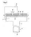
- the layer structure 20 comprises at least three layers, wherein directly on the first end 25, ie the end face of the screw head 2, a layer 23 of a piezoelectric Properties having sputtered material. The sputtering of the layer 23 takes place in a layer thickness of a few microns.
- the layer structure 20 according to the illustration in FIG. 2 at least one electrode layer 21. Within the electrode layer 21, individual electrodes are insulated from one another, indicated by a distance 26.
- the in FIG. 2 illustrated ultrasonic sensor 5 as a layer structure 20 may also be sputtered on a second end 27, which is also freely accessible.
- FIG. 2 What in FIG. 2 is exemplified by the example of a screw formed as a connecting component 1, can also be performed on a connecting member 1, which may be designed as a bolt, a rivet or a pin.
- the inventively proposed, integrated in the connecting member 1 ultrasonic sensor 5 in layer structure 20 is characterized by a high adhesion z. B. on the front end formed as a first end 25 of the connecting member 1. Due to the high adhesion of more than 40 newtons per mm 2 , all coupling errors which may affect the signal propagation time between the ultrasonic sensor 5 and the connecting component 1 - in particular an adhesive layer between the layer 23 and the first end 25 - are eliminated. As a result, a significantly more accurate signal propagation time measurement and thus a much more accurate determination of the preload force or the clamping force of the connection component 1 can be achieved.
- the connecting member 1 can be made from the group of materials listed below: high-alloy steels, special steels, titanium and its alloys, in particular TiAl6V4, and aluminum and its alloys, also brass, Inconel (nickel alloy) and steels, such. A286, which are non-magnetic.
- the inventively proposed ultrasonic sensor 5 is even after passing through a plurality of temperature cycles, by a short temperature raising time of a few minutes, a continuous temperature load at an elevated temperature level between 350 ° C and 500 ° C in an extreme case up to 1000 ° C and a slowly taking place Cooling are fully functional, there are no Operaabitesen within the layer structure 20, which may affect the signal propagation time of an ultrasonic signal.
- each layer within the layer structure 20, ie the at least one electrode layer 21, the at least one mechanical protective layer 22 and the at least one piezoelectric layer 23, is applied by way of the sputtering technique, prevail between the individual layers 21, 22, 23 of the layer structure 20 respectively high adhesion forces not only between the contact side of the layer 23 of a piezoelectric material having properties and the first end 25 of the connecting member 1, but also between the layers 21, 22, 23 with each other.
- An isolation of individual electrodes within the electrode layer 21 is preferably carried out by a masking technique, by which the in FIG. 2 shown distances 26 between the individual electrodes of the electrode layer 21 are generated.
- the layer 23 can be below the respective Curie temperature of the material with piezoelectric properties, from which the layer 23 is made to produce a reliable ultrasonic signal, which is a meaningful Ultrasonic measurement allows.
- the thickness of the layer 23 of material having piezoelectric properties exceeds the thickness of the mechanical protective layer 22 by a multiple, while the layer thickness in which the electrode layer 21 is made may substantially correspond to the thickness of the layer 23 of a material having piezoelectric properties ,
- the inventively proposed sensor element is received in a recess or depression on a first end side of the connecting member.
- FIG. 3 shows that in the embodiment according to FIG. 3 as a screw provided connection component 1 analogous to in FIG. 2 illustrated embodiment, the screw head 2, the shaft 3, the threaded part 4 and the ultrasonic sensor 5 receives.
- the ultrasonic sensor 5 as shown in FIG FIG. 3 is formed in the layer structure 20 and comprises the electrode layer 21, the mechanical protective layer, see reference numeral 22, and the piezoelectric layer 23.
- the layer structure 20 of the ultrasonic sensor 5 is embedded in a recess or recess 28 at the first end 25 of the connecting member 1.
- the recess or depression 28 at the first end 25 of the connection component 1 furthermore comprises a lateral boundary wall 29.
- the lateral boundary wall 29 has the advantageous effect of the layer structure 20 of the ultrasonic sensor 5 covers the material of the connection component 1, which is a stainless steel material or a high-alloy steel, the side surfaces of the layer structure 20, ie the electrode layer 21, the mechanical protective layer 22 and the piezoelectric layer 23. Thereby, diffusion of hydrogen molecules into the piezoelectric layer 23 in particular, oxidation and deoxidation of the piezoelectric layer 23, and contamination by impurities into the piezoelectric layer 23 can be effectively prevented.
- the compact protective layer 22 prevents the diffusion of foreign molecules into the piezoelectric layer 23 as well as the oxidation and deoxidation of the piezoelectric layer 23.
- a lateral protection of the layer structure 20 of the ultrasonic sensor 5 against oxidation and deoxidation and against diffusion of hydrogen molecules takes place by embedding it in the recess or depression 28 at the first end 25 of the connection component 1.
- the layer structure 20 of the ultrasonic sensor 5 is inserted into the recess or the recess 28 at the first end 25 in the end face of the connecting member 1.
- the layer structure 20 constructed ultrasonic sensor 5 is used at temperatures of at least 200 ° C, preferably at temperatures between 250 ° C and 950 ° C.
- the piezoelectric layer 23 is made of a material such as ZnO. Exceeding the Curie temperature eliminates the piezo effect.
- the piezoelectric layer 23 is to be protected against oxidation and deoxidation.
- aluminum nitride or silicon oxide or barium titanate may also be used.
- the material from which the connecting component 1 is manufactured may be special steels, in particular non-oxidised special steels as well as high-alloyed steels such as TiAl6V4.
- the mechanical protective layer 22 disposed within the layer structure 20 is preferably made in conjunction with N, C or O, which is the bonding material preferably is a metallic material.
- the mechanical protective layer 22 can be made of carbides, nitrides, oxides, in each case in combination with titanium, zirconium, silicon, aluminum or chromium.
- metals with or without nitrogen for example titanium and TiN or the like, and chromium and CrN, or in another embodiment as metal alloy, for example NiCr to use.
- metal alloy for example NiCr
- the material from which the electrode layer 21 of the layer structure 20 of the ultrasonic sensor 5 is made preferably elements of groups IV, IVb, VIb, VIIIb, Ib, for example Sn, Ag, Ti or other metallic compounds with each other, so for example, NiCr used.
- the layer structure 20 as which the inventively proposed ultrasonic sensor 5 is formed, care must be taken that the layer structure 20 is formed compact and free of pores.
- the connecting component 1 is a screw in whose screw head 2 the inventively proposed ultrasonic sensor 5 is embedded.
- the connecting component 1 comprises a screw head 2, the shaft 3 and the threaded part 4 formed on its circumference. While the first end of the connecting component 1 is designated by reference numeral 25, the second end opposite this is designated by reference numeral 27.
- the according to FIG. 3 illustrated ultrasonic sensor 5 can be used as a high temperature sensor.
- the inventively proposed ultrasonic sensor is used as a high temperature sensor in a temperature range between 200 ° C and 1000 ° C, preferably in a temperature range between 250 ° C and 950 ° C and particularly preferably within a temperature range between 650 ° C and 900 ° C.
- the piezoelectric layer 23 is made of, for example, ZnO, while the material of which the connecting component 1 - here represented as a screw - is preferably special steels, non-oxidized special steels and high-alloy steels are resistant to high temperatures.
- the piezoelectric layer 21 may be made of aluminum nitride, silicon oxide or barium titanate in addition to the already mentioned ZnO.
- the mechanical protective layer 22 preferably uses metallic compounds with N or O, to protect the piezoelectric layer 23.
- the mechanical protective layer 22 is arranged below the electrode layer 21, but above the piezoelectric layer 23.
- the individual layers 21, 22, 23 of the layer structure 20 of the ultrasonic sensor 5 in the recess or recess 28 in the screw head 2 of the connecting member 1 is inserted. Through the recess 28, the piezoelectric layer 23 of the layer structure 20 is also protected from the side against diffusing foreign molecules and against oxidation and deoxidation.
- connection component 1 connecting member 2 screw head 3 shaft 4 threaded part 5 ultrasonic sensor 6 sound path 7 Duration of ultrasonic signal between coupling and decoupling from connection component 1 8th Ultrasonic pulse echo 9 electronic ultrasonic measuring device 10 pulse generator 11 power amplifier 12 transient 13 preamplifier 14 computer 15 Signal transmission line 20 Layer structure of ultrasonic sensor 5 21 electrode layer 22 mechanical protective layer 23 piezoelectric layer 24 Connection AC voltage 25 first end (front side screw head 2) 26 Distance individual electrodes 27 second end (threaded outlet connecting component) 28 Recess, recess 29 lateral boundary wall
Landscapes
- Physics & Mathematics (AREA)
- Engineering & Computer Science (AREA)
- General Engineering & Computer Science (AREA)
- General Physics & Mathematics (AREA)
- Mechanical Engineering (AREA)
- Acoustics & Sound (AREA)
- Investigating Or Analyzing Materials By The Use Of Ultrasonic Waves (AREA)
- Ultra Sonic Daignosis Equipment (AREA)
Claims (15)
- Composant de liaison (1) auquel est intégré un détecteur (5) d'ultrasons qui détermine la force de précontrainte ou la force de serrage du composant de liaison (1),
le détecteur (5) d'ultrasons présentant une structure stratifiée (20) dotée d'une couche d'électrode (21), d'au moins une couche de protection mécanique (22) et d'au moins une couche (23) en un matériau présentant des propriétés piézoélectriques et
la ou les couches d'électrode (21), la ou les couches de protection mécanique (22) et la ou les couches (23) en matériau présentant des propriétés piézoélectriques étant pulvérisées sur une extrémité (25, 27) librement accessible du composant de liaison (1),
caractérisé en ce que
la structure stratifiée (20) est compacte et exempte de pores,
en ce que le détecteur (5) d'ultrasons est conçu pour traverser sans dommage un cycle de température qui présente une courte période de chauffage, une période au cours de laquelle règne un haut niveau de température et une période de refroidissement, par le fait que la couche de protection mécanique (22) sépare la couche (23) en matériau à propriétés piézoélectriques de la couche d'électrode (21). - Composant de liaison selon la revendication 1, caractérisé en ce que le composant de liaison (1) est utilisé comme sonde de haute température dans une plage de température comprise entre 200°C et 1 000°C, de préférence entre 250°C et 950°C et de façon particulièrement préférable dans une plage de température comprise entre 650°C et 900°C.
- Composant de liaison selon la revendication 1, caractérisé en ce qu'il est réalisé en l'un des matériaux de l'ensemble constitué des aciers fortement alliés, des aciers spéciaux, du titane et de ses alliages, du TiAl6V4, de l'aluminium et de ses alliages, les alliages de nickel (inconel), des aciers amagnétiques, par exemple l'acier A286, et du laiton.
- Composant de liaison selon la revendication 1, caractérisé en ce que l'épaisseur de la couche de protection mécanique (22) est de plusieurs ordres de grandeurs plus petite que l'épaisseur de la couche (23) en matériau présentant des propriétés piézoélectriques.
- Composant de liaison selon la revendication 1, caractérisé en ce que les couches (21, 22, 23) de la structure stratifiée (20) sont appliquées les unes sur les autres avec une force d'adhérence comprise entre 20 N/mm2 et 80 N/mm2, de préférence de 50 N/mm2 et de façon particulièrement préférable de 40 N/mm2.
- Composant de liaison selon la revendication 1, caractérisé en ce que la couche (23) en matériau présentant des propriétés piézoélectriques est appliquée à une force d'adhérence supérieure à 40 Newton par mm2 sur la première extrémité (25) ou sur une deuxième extrémité (27) du composant de liaison (1).
- Composant de liaison selon la revendication 1, caractérisé en ce que le détecteur (5) à ultrasons délivre un écho (8) d'impulsions ultrasonores concluantes dans une couche (23) lorsque la température de Curie du matériau présentant des propriétés piézoélectriques n'est plus atteinte.
- Composant de liaison selon la revendication 1, caractérisé en ce que l'épaisseur de la couche d'électrode (21) est < 30 µm.
- Composant de liaison selon la revendication 1, caractérisé en ce que l'épaisseur de la couche de protection mécanique (22) est < 20 µm.
- Composant de liaison selon la revendication 1, caractérisé en ce que l'épaisseur de la couche (23) en matériau présentant des propriétés piézoélectriques est < 50 µm.
- Composant de liaison selon la revendication 1, caractérisé en ce que la première extrémité (25) est le côté frontal d'une tête filetée (2).
- Composant de liaison selon la revendication 1, caractérisé en ce que la deuxième extrémité (27) est le côté frontal de l'extrémité d'une partie filetée (4).
- Composant de liaison selon la revendication 1, caractérisé en ce qu'elle est configurée comme vis, comme vis creuse, comme goujon fixe, comme goujon, comme rivet, comme tige ou comme composant spécial pour applications aérospatiales.
- Composant de liaison selon la revendication 1, caractérisé en ce que le détecteur (5) d'ultrasons intégré est introduit dans un logement ou un creux (28) formés dans la première extrémité (25) librement accessible du composant de liaison (1).
- Composant de liaison selon la revendication 14, caractérisé en ce que la structure stratifiée (20) du détecteur (5) d'ultrasons est incorporée dans la première extrémité (25) ou dans la deuxième extrémité (27) du composant de liaison (1).
Applications Claiming Priority (2)
| Application Number | Priority Date | Filing Date | Title |
|---|---|---|---|
| DE202006006990U DE202006006990U1 (de) | 2006-04-27 | 2006-04-27 | Verbindungsbauteil mit temperaturfestem Sensorelement |
| PCT/EP2007/003739 WO2007124924A2 (fr) | 2006-04-27 | 2007-04-27 | Composant de jonction présentant un élément détecteur thermorésistant |
Publications (2)
| Publication Number | Publication Date |
|---|---|
| EP2010883A2 EP2010883A2 (fr) | 2009-01-07 |
| EP2010883B1 true EP2010883B1 (fr) | 2013-06-12 |
Family
ID=36746544
Family Applications (1)
| Application Number | Title | Priority Date | Filing Date |
|---|---|---|---|
| EP07724667.6A Active EP2010883B1 (fr) | 2006-04-27 | 2007-04-27 | Composant de jonction présentant un élément détecteur thermorésistant |
Country Status (6)
| Country | Link |
|---|---|
| US (1) | US8177464B2 (fr) |
| EP (1) | EP2010883B1 (fr) |
| DE (1) | DE202006006990U1 (fr) |
| DK (1) | DK2010883T3 (fr) |
| ES (1) | ES2427157T3 (fr) |
| WO (1) | WO2007124924A2 (fr) |
Cited By (1)
| Publication number | Priority date | Publication date | Assignee | Title |
|---|---|---|---|---|
| EP4221927B1 (fr) * | 2020-10-01 | 2025-01-29 | Intellifast GmbH | Procédé de production de composants de liaison indicateurs de charge, et composant de liaison indicateur de charge |
Families Citing this family (27)
| Publication number | Priority date | Publication date | Assignee | Title |
|---|---|---|---|---|
| US20090206705A1 (en) | 2008-02-19 | 2009-08-20 | Nies Jacob J | Fasteners with welded ultrasonic stress transducers |
| DE102009060441B4 (de) * | 2009-12-22 | 2014-11-20 | Amg Intellifast Gmbh | Sensorelement |
| DE102010006402A1 (de) * | 2010-02-01 | 2011-08-04 | Audi Ag, 85057 | Verfahren zum Überwachen eines Hochgeschwindigkeits-Fügeprozesses zum Verbinden mindestens zweier Bauteile mittels eines Nagels |
| CN101864845B (zh) * | 2010-06-22 | 2012-06-06 | 湖南科技大学 | 监测加固工程预紧力动态的预应力钢杆智能锚固系统 |
| EP2490017A1 (fr) * | 2011-02-18 | 2012-08-22 | AMG Intellifast GmbH | Système de mesure d'ultrasons |
| CN102435363B (zh) * | 2011-09-21 | 2015-03-11 | 陈威 | 能进行超声波精确测量的具有超声波传感器的连接件及工艺和用途 |
| US9429546B2 (en) * | 2013-03-22 | 2016-08-30 | Siemens Energy, Inc. | Phased array ultrasonic bolt inspection apparatus and method |
| TWM484023U (zh) * | 2014-03-03 | 2014-08-11 | Kabo Tool Co | 感應螺絲應力防塵結構 |
| DE102014113504A1 (de) * | 2014-09-18 | 2016-03-24 | Airbus Operations Gmbh | Identifikation von fehlerhaften Nietverbindungen |
| KR101685890B1 (ko) * | 2015-01-20 | 2016-12-28 | 현대자동차주식회사 | 음파 센서 장치 |
| FR3033408B1 (fr) * | 2015-03-04 | 2021-01-29 | Areva Np | Dispositif d'inspection d'organes de fixation par ultrasons, et procede associe |
| CN107044896B (zh) * | 2017-03-27 | 2023-03-24 | 欧朋达科技(深圳)有限公司 | 结合力检测装置 |
| US10190618B2 (en) * | 2017-06-22 | 2019-01-29 | Caterpillar Inc. | Track bolt |
| DE102018212558A1 (de) * | 2018-07-27 | 2020-01-30 | Robert Bosch Gmbh | Ankervorrichtung |
| JP6678708B2 (ja) * | 2018-08-03 | 2020-04-08 | 本田技研工業株式会社 | ボルト軸力測定方法及びこの方法に使用するボルト |
| CN109632006A (zh) * | 2019-01-11 | 2019-04-16 | 重庆大学 | 一种无线智能螺栓及在线监测系统 |
| CN110285125B (zh) * | 2019-05-17 | 2024-10-01 | 杭州戬威科技有限公司 | 一种粘接式探头封装和智能螺栓 |
| DE102019119258A1 (de) * | 2019-07-16 | 2021-01-21 | VAG GmbH | Armatur |
| CN110425209A (zh) * | 2019-08-30 | 2019-11-08 | 航天精工股份有限公司 | 一种具有凹槽结构的螺纹紧固件 |
| CN111504541B (zh) * | 2020-04-20 | 2021-07-23 | 中物院成都科学技术发展中心 | 适于高腐蚀环境下使用的具有应力传感功能的紧固件及薄膜换能传感系统 |
| CN111537131A (zh) * | 2020-04-20 | 2020-08-14 | 中物院成都科学技术发展中心 | 一种轴向预紧力单波测量方法 |
| CN111536909A (zh) * | 2020-04-20 | 2020-08-14 | 中物院成都科学技术发展中心 | 一种薄膜镀层质量及超声波紧固件的质量检测方法 |
| CN111504542A (zh) * | 2020-04-20 | 2020-08-07 | 中物院成都科学技术发展中心 | 适于高温环境下使用的具有应力传感功能的紧固件及薄膜换能传感系统 |
| CN112945450A (zh) * | 2021-01-29 | 2021-06-11 | 优势博研(北京)科技有限公司 | 一种基于超声波的螺栓轴力精确测试及数据分析系统 |
| US11592288B1 (en) * | 2021-09-13 | 2023-02-28 | Honda Motor Co., Ltd. | Ultrasound transmitting and receiving device and computer readable medium storing ultrasound transmitting and receiving program |
| CN113916422B (zh) * | 2021-09-29 | 2023-09-12 | 航天精工股份有限公司 | 一种用于空心类紧固件超声传感器加工中的绝缘遮蔽结构 |
| CN113915201A (zh) * | 2021-09-29 | 2022-01-11 | 航天精工股份有限公司 | 一种具有可追溯性传感器紧固件及其制备方法 |
Family Cites Families (12)
| Publication number | Priority date | Publication date | Assignee | Title |
|---|---|---|---|---|
| JPS5830752B2 (ja) * | 1977-09-13 | 1983-07-01 | 株式会社村田製作所 | 酸化亜鉛の圧電結晶膜 |
| US4214018A (en) * | 1978-08-14 | 1980-07-22 | Rca Corporation | Method for making adherent pinhole free aluminum films on pyroelectric and/or piezoelectric substrates |
| US4846001A (en) * | 1987-09-11 | 1989-07-11 | Sps Technologies, Inc. | Ultrasonic load indicating member |
| US4899591A (en) * | 1987-09-11 | 1990-02-13 | Sps Technologies, Inc. | Ultrasonic load indicating member, apparatus and method |
| US5029480A (en) * | 1990-02-05 | 1991-07-09 | Sps Technologies, Inc. | Ultrasonic load indicating member |
| US5131276A (en) * | 1990-08-27 | 1992-07-21 | Ultrafast, Inc. | Ultrasonic load indicating member with transducer |
| US5205176A (en) * | 1990-08-27 | 1993-04-27 | Ultrafast, Inc. | Ultrasonic load cell with transducer |
| DE4232254A1 (de) | 1992-07-21 | 1994-04-07 | Siemens Ag | Ultraschallprüfverfahren |
| DE4224035A1 (de) | 1992-07-21 | 1994-01-27 | Siemens Ag | Ultraschallprüfverfahren |
| FR2696215B1 (fr) * | 1992-09-25 | 1994-12-02 | Serge Bras | Elément d'assemblage et procédé et machine d'assemblage. |
| US5461923A (en) * | 1994-05-16 | 1995-10-31 | Raymond Engineering Inc. | Acoustic transducer, transducerized fastener and method of manufacture |
| DE102004038638B3 (de) | 2004-08-09 | 2006-06-08 | Pfw Technologies Gmbh | Verfahren zur Bestimmung der Spannkraft von Verbindungsbauteilen durch Ultraschallanregung |
-
2006
- 2006-04-27 DE DE202006006990U patent/DE202006006990U1/de not_active Expired - Lifetime
-
2007
- 2007-04-27 DK DK07724667.6T patent/DK2010883T3/da active
- 2007-04-27 EP EP07724667.6A patent/EP2010883B1/fr active Active
- 2007-04-27 WO PCT/EP2007/003739 patent/WO2007124924A2/fr not_active Ceased
- 2007-04-27 US US12/298,681 patent/US8177464B2/en not_active Expired - Fee Related
- 2007-04-27 ES ES07724667T patent/ES2427157T3/es active Active
Cited By (1)
| Publication number | Priority date | Publication date | Assignee | Title |
|---|---|---|---|---|
| EP4221927B1 (fr) * | 2020-10-01 | 2025-01-29 | Intellifast GmbH | Procédé de production de composants de liaison indicateurs de charge, et composant de liaison indicateur de charge |
Also Published As
| Publication number | Publication date |
|---|---|
| US8177464B2 (en) | 2012-05-15 |
| DK2010883T3 (da) | 2013-09-23 |
| WO2007124924A2 (fr) | 2007-11-08 |
| US20090183572A1 (en) | 2009-07-23 |
| EP2010883A2 (fr) | 2009-01-07 |
| DE202006006990U1 (de) | 2006-07-13 |
| WO2007124924A3 (fr) | 2008-03-13 |
| ES2427157T3 (es) | 2013-10-29 |
Similar Documents
| Publication | Publication Date | Title |
|---|---|---|
| EP2010883B1 (fr) | Composant de jonction présentant un élément détecteur thermorésistant | |
| DE102009060441B4 (de) | Sensorelement | |
| DE69127201T2 (de) | Ultraschall element mit wandler für anzeige der mechanichen beanspruchung | |
| DE102004038638B3 (de) | Verfahren zur Bestimmung der Spannkraft von Verbindungsbauteilen durch Ultraschallanregung | |
| DE102005018123B4 (de) | Verfahren zur Bewertung von Messwerten zur Erkennung einer Materialermüdung | |
| DE102006019942A1 (de) | Kraftmessvorrichtung zur Messung der Kraft bei Festkörperaktoren, Verfahren zur Messung einer Kraft sowie Verwendung der Kraftmessvorrichtung | |
| EP1484608A2 (fr) | Determination de dommage des structures a tester par des capteurs ultrasonores permanentement attachés et intégrants une unité de contrôle | |
| DE10124394A1 (de) | Verfahren und Vorrichtung zum Liefern einer dynamischen Ultraschall-Messung der Parameter von Wälzelementlagern | |
| EP2238406A1 (fr) | Sonde pour dispositif de détection capacitif et système de mesure de distance entre des éléments | |
| EP3093641B1 (fr) | Procédé de détermination d'une force de traction axiale appliquée à un composant | |
| DE202013010307U1 (de) | Verbindungsbauteil mit integriertem Ultraschallsensor | |
| EP2473818B1 (fr) | Dispositif pour mesurer et/ou enregistrer des distances et des variations de distance et dispositif pour mesurer et/ou enregistrer des contraintes mécaniques | |
| DE102007054374A1 (de) | Verfahren und Vorrichtung zur Kalibrierung eines in einem Kraftfahrzeug zum Antrieb eines Schaltventils betriebenen Piezo-Aktuators | |
| DE102011011764A1 (de) | Ultraschallmesssystem | |
| DE102018220915B4 (de) | Verfahren zur Bestimmung der Vorspannkraft von Verbindungsbauteilen mit inhomogener Temperaturverteilung | |
| DE102004008432A1 (de) | Dehnungsmessstreifen zur Erfassung von Dehnungen oder Stauchungen an Verformungskörpern | |
| DE102006010804A1 (de) | Hochtemperatur-Drucksensorelement, insbesondere zur Messung von Drücken innerhalb von Triebwerken, Verfahren zu dessen Herstellung und Bauteil für Triebwerke | |
| EP2342546B1 (fr) | Dispositif de détermination et/ou de surveillance d'une pression | |
| EP4264176B1 (fr) | Procédé de détermination sans contact de l'épaisseur de couche d'une peinture humide | |
| DE102016012564A1 (de) | Verbindungselement mit integriertem Sensor | |
| EP3837512B1 (fr) | Dispositif oscillant ultrasonore comprenant un capteur piézoélectrique | |
| EP3757536A1 (fr) | Dispositif de mesure de la force de contact et procédé de mesure d'une force de contact à l'aide d'un tel dispositif de mesure de la force de contact | |
| DE102010024808A1 (de) | Piezoresistiver Kraftsensor | |
| DE102010024806B4 (de) | Drehmoment-Messeinrichtung und Verfahren zur Drehmomentmessung | |
| DE102019203756A1 (de) | Verfahren zur Bestimmung einer auf ein Bewegungslager einwirkenden Kraft |
Legal Events
| Date | Code | Title | Description |
|---|---|---|---|
| PUAI | Public reference made under article 153(3) epc to a published international application that has entered the european phase |
Free format text: ORIGINAL CODE: 0009012 |
|
| 17P | Request for examination filed |
Effective date: 20081107 |
|
| AK | Designated contracting states |
Kind code of ref document: A2 Designated state(s): AT BE BG CH CY CZ DE DK EE ES FI FR GB GR HU IE IS IT LI LT LU LV MC MT NL PL PT RO SE SI SK TR |
|
| AX | Request for extension of the european patent |
Extension state: AL BA HR MK RS |
|
| DAX | Request for extension of the european patent (deleted) | ||
| 17Q | First examination report despatched |
Effective date: 20120725 |
|
| GRAP | Despatch of communication of intention to grant a patent |
Free format text: ORIGINAL CODE: EPIDOSNIGR1 |
|
| GRAS | Grant fee paid |
Free format text: ORIGINAL CODE: EPIDOSNIGR3 |
|
| GRAA | (expected) grant |
Free format text: ORIGINAL CODE: 0009210 |
|
| AK | Designated contracting states |
Kind code of ref document: B1 Designated state(s): AT BE BG CH CY CZ DE DK EE ES FI FR GB GR HU IE IS IT LI LT LU LV MC MT NL PL PT RO SE SI SK TR |
|
| REG | Reference to a national code |
Ref country code: GB Ref legal event code: FG4D Free format text: NOT ENGLISH |
|
| REG | Reference to a national code |
Ref country code: CH Ref legal event code: EP |
|
| REG | Reference to a national code |
Ref country code: AT Ref legal event code: REF Ref document number: 616857 Country of ref document: AT Kind code of ref document: T Effective date: 20130615 |
|
| REG | Reference to a national code |
Ref country code: IE Ref legal event code: FG4D Free format text: LANGUAGE OF EP DOCUMENT: GERMAN |
|
| REG | Reference to a national code |
Ref country code: DE Ref legal event code: R096 Ref document number: 502007011890 Country of ref document: DE Effective date: 20130808 |
|
| RAP2 | Party data changed (patent owner data changed or rights of a patent transferred) |
Owner name: AMG INTELLIFAST GMBH |
|
| REG | Reference to a national code |
Ref country code: DK Ref legal event code: T3 |
|
| REG | Reference to a national code |
Ref country code: CH Ref legal event code: NV Representative=s name: SCHMAUDER AND PARTNER AG PATENT- UND MARKENANW, CH |
|
| REG | Reference to a national code |
Ref country code: SE Ref legal event code: TRGR |
|
| REG | Reference to a national code |
Ref country code: NL Ref legal event code: T3 |
|
| REG | Reference to a national code |
Ref country code: ES Ref legal event code: FG2A Ref document number: 2427157 Country of ref document: ES Kind code of ref document: T3 Effective date: 20131029 |
|
| PG25 | Lapsed in a contracting state [announced via postgrant information from national office to epo] |
Ref country code: SI Free format text: LAPSE BECAUSE OF FAILURE TO SUBMIT A TRANSLATION OF THE DESCRIPTION OR TO PAY THE FEE WITHIN THE PRESCRIBED TIME-LIMIT Effective date: 20130612 Ref country code: LT Free format text: LAPSE BECAUSE OF FAILURE TO SUBMIT A TRANSLATION OF THE DESCRIPTION OR TO PAY THE FEE WITHIN THE PRESCRIBED TIME-LIMIT Effective date: 20130612 Ref country code: GR Free format text: LAPSE BECAUSE OF FAILURE TO SUBMIT A TRANSLATION OF THE DESCRIPTION OR TO PAY THE FEE WITHIN THE PRESCRIBED TIME-LIMIT Effective date: 20130913 |
|
| REG | Reference to a national code |
Ref country code: LT Ref legal event code: MG4D |
|
| PG25 | Lapsed in a contracting state [announced via postgrant information from national office to epo] |
Ref country code: BG Free format text: LAPSE BECAUSE OF FAILURE TO SUBMIT A TRANSLATION OF THE DESCRIPTION OR TO PAY THE FEE WITHIN THE PRESCRIBED TIME-LIMIT Effective date: 20130912 |
|
| PG25 | Lapsed in a contracting state [announced via postgrant information from national office to epo] |
Ref country code: LV Free format text: LAPSE BECAUSE OF FAILURE TO SUBMIT A TRANSLATION OF THE DESCRIPTION OR TO PAY THE FEE WITHIN THE PRESCRIBED TIME-LIMIT Effective date: 20130612 |
|
| PG25 | Lapsed in a contracting state [announced via postgrant information from national office to epo] |
Ref country code: IS Free format text: LAPSE BECAUSE OF FAILURE TO SUBMIT A TRANSLATION OF THE DESCRIPTION OR TO PAY THE FEE WITHIN THE PRESCRIBED TIME-LIMIT Effective date: 20131012 Ref country code: SK Free format text: LAPSE BECAUSE OF FAILURE TO SUBMIT A TRANSLATION OF THE DESCRIPTION OR TO PAY THE FEE WITHIN THE PRESCRIBED TIME-LIMIT Effective date: 20130612 Ref country code: PT Free format text: LAPSE BECAUSE OF FAILURE TO SUBMIT A TRANSLATION OF THE DESCRIPTION OR TO PAY THE FEE WITHIN THE PRESCRIBED TIME-LIMIT Effective date: 20131014 Ref country code: EE Free format text: LAPSE BECAUSE OF FAILURE TO SUBMIT A TRANSLATION OF THE DESCRIPTION OR TO PAY THE FEE WITHIN THE PRESCRIBED TIME-LIMIT Effective date: 20130612 |
|
| PG25 | Lapsed in a contracting state [announced via postgrant information from national office to epo] |
Ref country code: PL Free format text: LAPSE BECAUSE OF FAILURE TO SUBMIT A TRANSLATION OF THE DESCRIPTION OR TO PAY THE FEE WITHIN THE PRESCRIBED TIME-LIMIT Effective date: 20130612 Ref country code: RO Free format text: LAPSE BECAUSE OF FAILURE TO SUBMIT A TRANSLATION OF THE DESCRIPTION OR TO PAY THE FEE WITHIN THE PRESCRIBED TIME-LIMIT Effective date: 20130612 |
|
| PLBE | No opposition filed within time limit |
Free format text: ORIGINAL CODE: 0009261 |
|
| STAA | Information on the status of an ep patent application or granted ep patent |
Free format text: STATUS: NO OPPOSITION FILED WITHIN TIME LIMIT |
|
| 26N | No opposition filed |
Effective date: 20140313 |
|
| REG | Reference to a national code |
Ref country code: DE Ref legal event code: R097 Ref document number: 502007011890 Country of ref document: DE Effective date: 20140313 |
|
| PG25 | Lapsed in a contracting state [announced via postgrant information from national office to epo] |
Ref country code: LU Free format text: LAPSE BECAUSE OF FAILURE TO SUBMIT A TRANSLATION OF THE DESCRIPTION OR TO PAY THE FEE WITHIN THE PRESCRIBED TIME-LIMIT Effective date: 20140427 Ref country code: MC Free format text: LAPSE BECAUSE OF FAILURE TO SUBMIT A TRANSLATION OF THE DESCRIPTION OR TO PAY THE FEE WITHIN THE PRESCRIBED TIME-LIMIT Effective date: 20130612 |
|
| PG25 | Lapsed in a contracting state [announced via postgrant information from national office to epo] |
Ref country code: MT Free format text: LAPSE BECAUSE OF FAILURE TO SUBMIT A TRANSLATION OF THE DESCRIPTION OR TO PAY THE FEE WITHIN THE PRESCRIBED TIME-LIMIT Effective date: 20130612 |
|
| REG | Reference to a national code |
Ref country code: FR Ref legal event code: PLFP Year of fee payment: 10 |
|
| PG25 | Lapsed in a contracting state [announced via postgrant information from national office to epo] |
Ref country code: CY Free format text: LAPSE BECAUSE OF FAILURE TO SUBMIT A TRANSLATION OF THE DESCRIPTION OR TO PAY THE FEE WITHIN THE PRESCRIBED TIME-LIMIT Effective date: 20130612 |
|
| PG25 | Lapsed in a contracting state [announced via postgrant information from national office to epo] |
Ref country code: HU Free format text: LAPSE BECAUSE OF FAILURE TO SUBMIT A TRANSLATION OF THE DESCRIPTION OR TO PAY THE FEE WITHIN THE PRESCRIBED TIME-LIMIT; INVALID AB INITIO Effective date: 20070427 |
|
| PGFP | Annual fee paid to national office [announced via postgrant information from national office to epo] |
Ref country code: TR Payment date: 20160419 Year of fee payment: 10 |
|
| REG | Reference to a national code |
Ref country code: FR Ref legal event code: PLFP Year of fee payment: 11 |
|
| PGFP | Annual fee paid to national office [announced via postgrant information from national office to epo] |
Ref country code: NL Payment date: 20170424 Year of fee payment: 11 |
|
| PGFP | Annual fee paid to national office [announced via postgrant information from national office to epo] |
Ref country code: CH Payment date: 20170425 Year of fee payment: 11 Ref country code: DK Payment date: 20170424 Year of fee payment: 11 Ref country code: CZ Payment date: 20170420 Year of fee payment: 11 |
|
| PGFP | Annual fee paid to national office [announced via postgrant information from national office to epo] |
Ref country code: SE Payment date: 20170425 Year of fee payment: 11 Ref country code: FI Payment date: 20170420 Year of fee payment: 11 Ref country code: BE Payment date: 20170424 Year of fee payment: 11 Ref country code: AT Payment date: 20170420 Year of fee payment: 11 |
|
| REG | Reference to a national code |
Ref country code: FR Ref legal event code: PLFP Year of fee payment: 12 |
|
| REG | Reference to a national code |
Ref country code: DK Ref legal event code: EBP Effective date: 20180430 |
|
| REG | Reference to a national code |
Ref country code: CH Ref legal event code: PL |
|
| REG | Reference to a national code |
Ref country code: SE Ref legal event code: EUG |
|
| REG | Reference to a national code |
Ref country code: NL Ref legal event code: MM Effective date: 20180501 |
|
| REG | Reference to a national code |
Ref country code: AT Ref legal event code: MM01 Ref document number: 616857 Country of ref document: AT Kind code of ref document: T Effective date: 20180427 |
|
| REG | Reference to a national code |
Ref country code: BE Ref legal event code: MM Effective date: 20180430 |
|
| REG | Reference to a national code |
Ref country code: IE Ref legal event code: MM4A |
|
| PG25 | Lapsed in a contracting state [announced via postgrant information from national office to epo] |
Ref country code: SE Free format text: LAPSE BECAUSE OF NON-PAYMENT OF DUE FEES Effective date: 20180428 Ref country code: AT Free format text: LAPSE BECAUSE OF NON-PAYMENT OF DUE FEES Effective date: 20180427 Ref country code: CZ Free format text: LAPSE BECAUSE OF NON-PAYMENT OF DUE FEES Effective date: 20180427 Ref country code: NL Free format text: LAPSE BECAUSE OF NON-PAYMENT OF DUE FEES Effective date: 20180501 Ref country code: FI Free format text: LAPSE BECAUSE OF NON-PAYMENT OF DUE FEES Effective date: 20180427 |
|
| PG25 | Lapsed in a contracting state [announced via postgrant information from national office to epo] |
Ref country code: CH Free format text: LAPSE BECAUSE OF NON-PAYMENT OF DUE FEES Effective date: 20180430 Ref country code: LI Free format text: LAPSE BECAUSE OF NON-PAYMENT OF DUE FEES Effective date: 20180430 Ref country code: BE Free format text: LAPSE BECAUSE OF NON-PAYMENT OF DUE FEES Effective date: 20180430 |
|
| PG25 | Lapsed in a contracting state [announced via postgrant information from national office to epo] |
Ref country code: IE Free format text: LAPSE BECAUSE OF NON-PAYMENT OF DUE FEES Effective date: 20180427 |
|
| PG25 | Lapsed in a contracting state [announced via postgrant information from national office to epo] |
Ref country code: DK Free format text: LAPSE BECAUSE OF NON-PAYMENT OF DUE FEES Effective date: 20180430 |
|
| PGFP | Annual fee paid to national office [announced via postgrant information from national office to epo] |
Ref country code: IT Payment date: 20190419 Year of fee payment: 13 Ref country code: ES Payment date: 20190520 Year of fee payment: 13 |
|
| PGFP | Annual fee paid to national office [announced via postgrant information from national office to epo] |
Ref country code: FR Payment date: 20190423 Year of fee payment: 13 |
|
| PGFP | Annual fee paid to national office [announced via postgrant information from national office to epo] |
Ref country code: GB Payment date: 20190424 Year of fee payment: 13 |
|
| PG25 | Lapsed in a contracting state [announced via postgrant information from national office to epo] |
Ref country code: FR Free format text: LAPSE BECAUSE OF NON-PAYMENT OF DUE FEES Effective date: 20200430 |
|
| GBPC | Gb: european patent ceased through non-payment of renewal fee |
Effective date: 20200427 |
|
| PG25 | Lapsed in a contracting state [announced via postgrant information from national office to epo] |
Ref country code: GB Free format text: LAPSE BECAUSE OF NON-PAYMENT OF DUE FEES Effective date: 20200427 |
|
| REG | Reference to a national code |
Ref country code: ES Ref legal event code: FD2A Effective date: 20210906 |
|
| PG25 | Lapsed in a contracting state [announced via postgrant information from national office to epo] |
Ref country code: IT Free format text: LAPSE BECAUSE OF NON-PAYMENT OF DUE FEES Effective date: 20200427 |
|
| PG25 | Lapsed in a contracting state [announced via postgrant information from national office to epo] |
Ref country code: ES Free format text: LAPSE BECAUSE OF NON-PAYMENT OF DUE FEES Effective date: 20200428 |
|
| PG25 | Lapsed in a contracting state [announced via postgrant information from national office to epo] |
Ref country code: TR Free format text: LAPSE BECAUSE OF NON-PAYMENT OF DUE FEES Effective date: 20170427 |
|
| P01 | Opt-out of the competence of the unified patent court (upc) registered |
Effective date: 20230530 |
|
| PGFP | Annual fee paid to national office [announced via postgrant information from national office to epo] |
Ref country code: DE Payment date: 20250429 Year of fee payment: 19 |