EP2010894B1 - Wasserstoffsensor - Google Patents
Wasserstoffsensor Download PDFInfo
- Publication number
- EP2010894B1 EP2010894B1 EP07724409A EP07724409A EP2010894B1 EP 2010894 B1 EP2010894 B1 EP 2010894B1 EP 07724409 A EP07724409 A EP 07724409A EP 07724409 A EP07724409 A EP 07724409A EP 2010894 B1 EP2010894 B1 EP 2010894B1
- Authority
- EP
- European Patent Office
- Prior art keywords
- sensor
- hydrogen
- medium
- sensor medium
- radiation
- Prior art date
- Legal status (The legal status is an assumption and is not a legal conclusion. Google has not performed a legal analysis and makes no representation as to the accuracy of the status listed.)
- Active
Links
Images

Classifications
-
- G—PHYSICS
- G01—MEASURING; TESTING
- G01N—INVESTIGATING OR ANALYSING MATERIALS BY DETERMINING THEIR CHEMICAL OR PHYSICAL PROPERTIES
- G01N21/00—Investigating or analysing materials by the use of optical means, i.e. using sub-millimetre waves, infrared, visible or ultraviolet light
- G01N21/75—Systems in which material is subjected to a chemical reaction, the progress or the result of the reaction being investigated
- G01N21/77—Systems in which material is subjected to a chemical reaction, the progress or the result of the reaction being investigated by observing the effect on a chemical indicator
- G01N21/78—Systems in which material is subjected to a chemical reaction, the progress or the result of the reaction being investigated by observing the effect on a chemical indicator producing a change of colour
- G01N21/783—Systems in which material is subjected to a chemical reaction, the progress or the result of the reaction being investigated by observing the effect on a chemical indicator producing a change of colour for analysing gases
-
- G—PHYSICS
- G01—MEASURING; TESTING
- G01N—INVESTIGATING OR ANALYSING MATERIALS BY DETERMINING THEIR CHEMICAL OR PHYSICAL PROPERTIES
- G01N33/00—Investigating or analysing materials by specific methods not covered by groups G01N1/00 - G01N31/00
- G01N33/0004—Gaseous mixtures, e.g. polluted air
- G01N33/0009—General constructional details of gas analysers, e.g. portable test equipment
- G01N33/0027—General constructional details of gas analysers, e.g. portable test equipment concerning the detector
- G01N33/0036—General constructional details of gas analysers, e.g. portable test equipment concerning the detector specially adapted to detect a particular component
- G01N33/005—H2
-
- G—PHYSICS
- G01—MEASURING; TESTING
- G01N—INVESTIGATING OR ANALYSING MATERIALS BY DETERMINING THEIR CHEMICAL OR PHYSICAL PROPERTIES
- G01N21/00—Investigating or analysing materials by the use of optical means, i.e. using sub-millimetre waves, infrared, visible or ultraviolet light
- G01N21/75—Systems in which material is subjected to a chemical reaction, the progress or the result of the reaction being investigated
- G01N21/77—Systems in which material is subjected to a chemical reaction, the progress or the result of the reaction being investigated by observing the effect on a chemical indicator
- G01N2021/7769—Measurement method of reaction-produced change in sensor
- G01N2021/7783—Transmission, loss
-
- G—PHYSICS
- G01—MEASURING; TESTING
- G01N—INVESTIGATING OR ANALYSING MATERIALS BY DETERMINING THEIR CHEMICAL OR PHYSICAL PROPERTIES
- G01N2201/00—Features of devices classified in G01N21/00
- G01N2201/08—Optical fibres; light guides
Definitions
- the invention relates to a hydrogen sensor comprising a radiation source, by means of which electromagnetic radiation is radiated onto a sensor medium, the sensor medium having a transmission coefficient which varies as a function of the concentration of hydrogen in the environment of the sensor medium, and a detector comprising at least a part of the sensor detected by the sensor medium transmitted rays detected.
- a thin palladium layer or a layer of a palladium cluster layer serves to exploit the physical effect that the optical transmission of the palladium layer changes in the presence of hydrogen in the vicinity of the palladium layer. This happens through storage or chemical reaction of hydrogen with the palladium, whereby the electronic structure of the palladium, in particular around the Fermikante changes.
- US Pat. No. 6,535,658 B1 relates to a hydrogen sensor based on a porous glass rod.
- the porous glass rod forms a glass matrix, which is first treated with tungsten oxide after its preparation, whereby tungsten oxide is bound to oxygen atoms in the pores of the glass, and then with palladium, which is treated by a heat treatment at 500 ° C so that a palladium Coating or a palladium layer forms on the surface of the pores of the glass rod.
- US Pat. No. 4,661,320 discloses a gas sensor with a device in which in the presence of hydrogen, the light absorption is changed.
- a device using the sensor is in the form of a laminate of a metal which absorbs and dissociates hydrogen or the gas of a hydrogen-containing compound, and a solid compound which changes light absorption by the hydrogen atoms formed in the metal , is reduced.
- US 2005/169807 A1 relates to an optical transmission hydrogen sensor with a thin film of hydrogen-sensitive material of a palladium alloy, for example a palladium / gold alloy.
- the thin layer has a nanocrystalline Structure on.
- EP 0 120 231 A discloses a device for gas detection with a metal oxide sensor using oxides or oxide mixtures of a plurality of elements.
- a hydrogen sensor with a radiation source are irradiated by the electromagnetic radiation to a sensor medium, wherein the sensor medium has a transmission coefficient which varies depending on the concentration of hydrogen in the environment of the sensor medium, and with a detector, the at least one Part of the transmitted through the sensor medium radiation detected, wherein the sensor medium cluster comprising or consisting of a palladium alloy, yttrium, scandium, at least one lanthanide, at least one actinide, tungsten oxide and / or vanadium oxide and / or a mixture or compound of these materials, wherein the Clusters are embedded in a matrix of a polymer.
- a particularly durable sensor medium capable of accepting high levels of hydrogen without damage is because the sensing medium is a cluster of palladium alloys, yttrium, scandium, at least one lanthanide, at least one actinide, tungsten oxide and / or vanadium oxide, and / or a mixture or connection comprising these materials.
- palladium alloys are used in particular palladium alloys with iron, nickel and tungsten.
- the lanthanides are elements 57 to 71 of the Periodic Table of the Elements.
- the actinides are elements 89 to 103 of the Periodic Table of the Elements.
- Clusters are in the context of the invention, in particular accumulations of chemically or physically bonded atoms of the aforementioned materials. Clusters may in particular also be crystals or crystallites.
- the sensor medium is a composite of clusters and another material in which the clusters are embedded, namely a matrix of a polymer. In this way, the changes in the lattice constants of the material that make up the clusters or which contain the clusters can be compensated for in the presence of different hydrogen concentrations, so that the sensor medium then not with too high a proportion of hydrogen in the sensor medium or with repeated loading with Hydrogen degraded or irreversibly destroyed.
- the tungsten oxide is present in a chemical formula WO 3 .
- Vanadium oxide is preferably present in a chemical formula V 2 O 5 .
- the materials preferably form metal hydrides with hydrogen, such as metal H 3 .
- the clusters are embedded in a matrix of a polymer.
- the clusters have a diameter from 1 nm to 30 nm, in particular 2 nm to 15 nm, in particular 3 nm to 10 nm, preferably to 3 to 5 nm.
- the clusters are preferably nanocrystallites or nanocrystals.
- the polymer preferably comprises or consists of polytetrafluoroethylene, polyterephthalate, polyimide, polymethylmethacrylate and / or polycarbonate.
- the sensor medium is applied to a substrate.
- the handling of the sensor medium is improved.
- a buffer layer is provided between the substrate and the sensor medium, differences to the lattice constants between the substrate and the sensor medium can be compensated.
- a buffer layer calcium fluoride (CaF 2 ).
- the substrate is preferably transparent to the electromagnetic radiation, or substantially transparent, and preferably non-reactive to hydrogen.
- a cover layer is preferably provided on the sensor medium, which in particular is preferably transparent, does not react with hydrogen or is substantially non-reactive and / or hydrogen-permeable, the sensor medium is also arranged protected in the sensor.
- the cover layer may also be partially reflective, so that a not only two-fold passage of the electromagnetic radiation through the sensor medium can be generated, but also a multiple passage.
- the sensor medium is formed as a layer. If a cover layer is provided on the sensor medium, this may serve to protect the sensor medium and / or may also be reflective in order to enable that the electromagnetic radiation can be transmitted several times through the sensor medium.
- platinum, gold or another inert material can be used as cover layer in particular.
- the thickness of the cover layer in this case should be so thin that hydrogen can diffuse through without problems and also the electromagnetic radiation, which are preferably in the range of visible or ultraviolet light, can pass through at least in sections.
- the electromagnetic radiation which are preferably in the range of visible or ultraviolet light
- no cover layer or a cover layer transparent to these rays is provided at the point where the electromagnetic radiation hits the sensor medium for the first time.
- These rays are then preferably transmitted through the sensor medium, pass to a mirror, are reflected, and redirected through the sensor medium to a cover layer which is reflective to the electromagnetic radiation to be redirected through the sensor medium and again to be transported through the sensor medium to then exit the sensor medium and be routed to a detector.
- the sensor medium in relation to the thickness of the sensor medium four times as sensitive as conventional sensor media or sensors at the same thickness.
- the sensor medium is formed as a layer.
- the hydrogen sensor according to the invention uses the basic idea of using the sensor medium at least twice, in order to enable a high sensitivity of the sensor with little material expenditure, which leads to stable sensor media, and a long service life.
- correspondingly thick layers usually from palladium or palladium clusters find use, which replace the substrate from a correspondingly high loading with hydrogen, for example of more than 10% in the palladium clusters and over 4% in crystalline layers after a few loading cycles with hydrogen, so that the sensor no reproducible results provides more.
- the solution according to the invention of letting the electromagnetic radiation travel at least twice through the sensor medium makes it possible to use a very thin sensor medium which does not result in a corresponding degradation of the sensor medium due to frequent loading with hydrogen or due to a high concentration of hydrogen in the environment of the sensor medium leads.
- the substrate is the reflector or a reflector is applied to the substrate.
- the sensor medium is preferably applied to the upper side of the substrate and a reflective surface is applied to the underside or rear side.
- the substrate may be glass or a mirror, for example.
- a very well manageable hydrogen sensor is given when the electromagnetic radiation is passed with at least a first optical fiber from a radiation source to the sensor medium.
- the rays reflected by the reflector and transmitted through the sensor medium are conducted to the detector with at least one second optical fiber.
- the at least one first and the at least one second optical waveguide preferably extend, at least in sections, substantially parallel or are arranged in such a way.
- the optical fibers extend substantially completely over the entire length parallel to each other.
- a lens focusing the beams is provided on the end of the at least one first and / or second optical waveguide facing the sensor medium.
- the focus of the lens is preferably set to the mirror surface or the sensor medium.
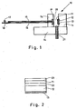
- Fig. 1 shows a schematic sectional view through an inventive Sensor 10.
- the measuring principle of the sensor is based on the measurement of the intensity change of a light signal.
- the signal or the rays are generated by means of a light-emitting diode or light source 17, preferably with a wavelength of 350 to 450 nm.
- the light which is preferably in the ultraviolet, is coupled directly into an ultraviolet optical waveguide 15, in particular 400 microns in diameter.
- the beams are directed perpendicular to the functional layer or sensor layer 11.
- a collimator lens 19 can serve.
- the later measurement signal is higher with the same light output.
- the arrangement also works without a collimator lens 19, since in particular the coupling of the reflected light into the optical waveguide 15 leading to the detector 18 is based on the scattering of the light on the nanostructured sensor layer 11.
- the medium to be measured in the environment 20 is arranged between the collimator lens 19 or in the variant without collimator lens between the optical waveguide 15 or 16 and the sensor layer 11.
- the distance between the collimator lens 19 and the optical waveguides 15, 16 to the sensor layer 11 is a few millimeters.
- the rays penetrate or pass through the sensor layer 11 and, depending on the hydrogen content, are influenced correspondingly in terms of strength or power.
- the more hydrogen is provided in the environment 20, the more hydrogen can be incorporated into the sensor layer 11 and the active substance, in particular chemochromatic substance, there change so that the transmission coefficient is reduced. That is, the light transmitted through the sensor layer becomes dependent damped the concentration of hydrogen.
- the sensor layer 11 is preferably applied to a glass substrate or a substrate 12, such as a sapphire substrate or a strontium titanate substrate or a diamond substrate.
- the substrate 12 is provided with a reflective rear side 13, ie a mirror surface 13, whereby the beams are reflected and pass through the sensor layer 11 again. This leads to a renewed attenuation of the rays, which are coupled by a collimator lens 19 in the second optical waveguide 16.
- a detector in the form of a silicon photodiode is provided, which converts the optical beam or the optical signal into an electrical signal.
- the corresponding components are mounted on a holder 14.
- a gas supply line 21 is provided, which provides for the supply of possibly hydrogen-provided gas.
- the sensor is shown open. This is usually provided in a closed housing, not shown, with the exception of the gas supply line 21.
- a second opening or a second gas supply line 21 may also be provided.
- the sensor layer 11 is 40 nm or 50 nm thick in this embodiment. It may also preferably be 10 nm to 30 nm thick.
- the area of the sensor layer 11 is preferably at least as large as the beam area of the coupled-in beams.
- the sensor layer preferably consists of a nanocomposite comprising clusters 25 (cf. Fig. 3 ) in a size of 1 nm to 30 nm, in particular about 5 nm.
- Fig. 3 a transmission electron micrograph of the sensor layer 11 is shown.
- the dark areas are the metallic areas consisting for example of palladium alloy, yttrium, scandium, a lanthanide, an actinide, tungsten oxide and / or vanadium oxide.
- the gray or lighter areas consist of a polymer or a mixture of polymers, which form a kind of matrix in which the clusters are embedded.
- a size specification is provided at the bottom of the Fig. 3 .
- the white line indicated there against the black background has a length of 20 nm.
- D is intended to represent the approximate diameter of a cluster and is approximately 4 nm for the cluster shown.
- the polymer is polytetrafluoroethylene
- the nanocrystals or clusters 25 are made of palladium.
- the size of the clusters can be varied by annealing at temperatures below 300 ° C.
- Fig. 2 shows a sectional view through a substrate with correspondingly applied layers.
- the substrate 12 has provided on its underside a mirror surface 13.
- a buffer layer 22 for example a calcium fluoride layer.
- the nanocomposite layer 11 or sensor layer 11 is applied and in turn a cover layer 23, for example of platinum.
- the layers can be deposited on the substrate by sputtering, for example, magnetron sputtering or laser ablation, PECVD, sol-gel or spin-coating.
- the sensor layer 11 is in this exemplary embodiment 50 nm thick. However, this can be made down to 10 nm thickness with appropriate functionality. There are essentially no cross-sensitivities to other gases in the hazard area. This is due to the fact that the change in the optical transmission of the sensor layer or the composite film is only caused by changing the crystal structure of the cluster 25, in particular nanoclusters, which is observed exclusively under the influence of hydrogen.
- the sensor has a long service life, since the actual optically switching or the optical effect causing metal nanoclusters are embedded in a polymer matrix. Since the matrix consists of polymers, this can absorb the mechanical stress of the nanoclusters. There is no degeneration of the nanocomposite as well as of the whole structure. Thus, a long life can be achieved and measurements of hydrogen concentrations of up to 10% by volume and higher reproducible can be possible. Due to the purely optical mode of operation, 100% explosion protection is also provided in the hazardous area.
Landscapes
- Chemical & Material Sciences (AREA)
- Health & Medical Sciences (AREA)
- Engineering & Computer Science (AREA)
- Physics & Mathematics (AREA)
- Life Sciences & Earth Sciences (AREA)
- General Physics & Mathematics (AREA)
- Pathology (AREA)
- Analytical Chemistry (AREA)
- Biochemistry (AREA)
- General Health & Medical Sciences (AREA)
- Immunology (AREA)
- Chemical Kinetics & Catalysis (AREA)
- Plasma & Fusion (AREA)
- Combustion & Propulsion (AREA)
- Food Science & Technology (AREA)
- Medicinal Chemistry (AREA)
- Investigating Or Analysing Materials By The Use Of Chemical Reactions (AREA)
- Investigating Or Analysing Materials By Optical Means (AREA)
- Investigating, Analyzing Materials By Fluorescence Or Luminescence (AREA)
- Investigating Or Analyzing Non-Biological Materials By The Use Of Chemical Means (AREA)
Description
- Die Erfindung betrifft einen Wasserstoffsensor mit einer Strahlenquelle, mittels der elektromagnetische Strahlen auf ein Sensormedium gestrahlt werden, wobei das Sensormedium einen Transmissionskoeffizienten hat, der in Abhängigkeit der Konzentration von Wasserstoff in der Umgebung des Sensormediums variiert, und mit einem Detektor, der wenigstens einen Teil der durch das Sensormedium transmittierten Strahlen detektiert.
- Das physikalische Prinzip eines entsprechenden Sensors ist aus Petra Fedtke, Marion Wienecke, Mihaela-C. Bunescu, Marlis Pietrzak, K. Deistung, Erika Borchardt in "Hydrogen sensor based on optical and electrical switching", Sensors and Actuators B 100 (2004) 151-157, bekannt. Hierbei dient eine dünne Palladiumschicht bzw. eine Schicht aus einer Palladiumclusterschicht dazu, den physikalischen Effekt auszunutzen, dass die optische Transmission der Palladiumschicht sich bei Anwesenheit von Wasserstoff in der Umgebung der Palladiumschicht ändert. Dies geschieht durch Einlagerung bzw. chemische Reaktion von Wasserstoff mit dem Palladium, wodurch sich die elektronische Struktur des Palladiums, insbesondere um die Fermikante herum, ändert.
-
US 6 535 658 B1 betrifft einen Wasserstoffsensor auf der Grundlage eines porösen Glasstabs. Der poröse Glasstab bildet eine Glasmatrix, die nach ihrer Herstellung zunächst mit Wolframoxid behandelt wird, wobei Wolframoxid an Sauerstoffatome in den Poren des Glases gebunden wird, und anschließend mit Palladium, das durch eine Hitzebehandlung bei 500 °C so behandelt wird, dass sich ein Palladium-Überzug bzw. eine Palladium-Schicht auf der Oberfläche der Poren des Glasstabes bildet. - In
US 4 661 320 A ist ein Gassensor mit einer Einrichtung offenbart, in der in Gegenwart von Wasserstoff die Lichtabsorption geändert wird. Eine Einrichtung, die den Sensor verwendet, hat die Form eines Laminats aus einem Metall, das Wasserstoff oder das Gas einer Wasserstoff enthaltenden Verbindung absorbiert und dissoziiert, und einer festen Verbindung, die unter Änderung der Lichtabsorption durch die Wasserstoffatome, die in dem Metall gebildet werden, reduziert wird. -
US 2005/169807 A1 betrifft einen optischen Transmissionswasserstoffsensor mit einem dünnen Film aus wasserstoffsensitivem Material aus einer Palladiumlegierung, beispielsweise einer Palladium/Gold-Legierung. Die dünne Schicht weist eine nanokristalline Struktur auf. -
EP 0 120 231 A offenbart eine Vorrichtung für den Gasnachweis mit einem aus Metalloxid bestehenden Sensor, wobei Oxide oder Oxidmischungen einer Vielzahl von Elementen verwendet werden. - Es ist Aufgabe der vorliegenden Erfindung, den bekannten physikalischen Effekt für einen, insbesondere portablen, Wasserstoffsensor auszunutzen und derart weiter zu bilden, dass ein sehr effizienter Wasserstoffsensor angegeben wird, dessen Empfindlichkeit hoch ist. Ferner soll ein alternativer Wasserstoffsensor angegeben werden.
- Gelöst wird diese Aufgabe durch einen Wasserstoffsensor mit einer Strahlenquelle, mittels der elektromagnetische Strahlen auf ein Sensormedium gestrahlt werden, wobei das Sensormedium einen Transmissionskoeffizienten aufweist, der in Abhängigkeit der Konzentration von Wasserstoff in der Umgebung des Sensormediums variiert, und mit einem Detektor, der wenigstens einen Teil der durch das Sensormedium transmittierten Strahlen detektiert, wobei das Sensormedium Cluster enthaltend oder bestehend aus einer Palladiumlegierung, Yttrium, Scandium, wenigstens einem Lanthanid, wenigstens einem Actinoid, Wolframoxid und/oder Vanadiumoxid und/oder eine Mischung oder Verbindung dieser Materialien aufweist, wobei die Cluster in einer Matrix aus einem Polymer eingebettet sind.
- Ein besonders haltbares Sensormedium, das einen hohen Anteil an Wasserstoff aufnehmen kann, ohne Schäden aufzuweisen, liegt vor, da das Sensormedium Cluster aus Palladiumlegierungen, Yttrium, Scandium, wenigstens ein Lanthanid, wenigstens ein Actinoid, Wolframoxid und/oder Vanadiumoxid und/oder eine Mischung oder Verbindung dieser Materialien aufweist. Als Palladiumlegierungen dienen insbesondere Palladiumlegierungen mit Eisen, Nickel und Wolfram. Die Lanthanide sind die Elemente 57 bis 71 des Periodensystems der Elemente. Die Actinoide sind die Elemente 89 bis 103 des Periodensystems der Elemente.
- Cluster sind im Rahmen der Erfindung insbesondere Ansammlungen von miteinander chemisch oder physikalisch gebundenen Atomen der eben genannten Materialien. Cluster können insbesondere auch Kristalle oder Kristallite sein. Das Sensormedium ist ein Komposit aus Clustern und einem weiteren Material, in das die Cluster eingebettet sind, nämlich einer Matrix aus einem Polymer. Hierdurch können die Änderungen der Gitterkonstanten des Materials, aus dem die Cluster bestehen bzw. das die Cluster enthalten, bei Vorliegen von verschiedenen Wasserstoffkonzentrationen ausgeglichen werden, so dass das Sensormedium dann nicht bei zu hohem Anteil von Wasserstoff in dem Sensormedium bzw. bei wiederholter Beladung mit Wasserstoff degradiert bzw. irreversibel zerstört wird.
- Vorzugsweise liegt das Wolframoxid in einer chemischen Formel WO3 vor. Vorzugsweise liegt Vanadiumoxid in einer chemischen Formel V2O5 vor. Die Materialien bilden vorzugsweise mit Wasserstoff Metallhydride, wie beispielsweise Metall-H3.
- Durch Verwendung von Clustern enthaltend die bzw. bestehend aus den oben genannten Materialien wird ein Wasserstoffsensor mit einer hohen Lebensdauer und einer hohen Langzeitstabilität ermöglicht.
- Erfindungsgemäß sind die Cluster in einer Matrix aus einem Polymer eingebettet. Vorzugsweise haben die Cluster einen Durchmesser von 1 nm bis 30 nm, insbesondere 2 nm bis 15 nm, insbesondere 3 nm bis 10 nm, vorzugsweise bis 3 bis 5 nm. Die Cluster sind vorzugsweise Nanokristallite bzw. Nanokristalle.
- Das Polymer umfasst oder besteht vorzugsweise aus Polytetrafluorethylen, Polyterephthalat, Polyimid, Polymethylmethacrylat und/oder Polycarbonat.
- Vorzugsweise ist das Sensormedium auf einem Substrat aufgebracht. Hierdurch wird die Handhabbarkeit des Sensormediums verbessert.
- Wenn zwischen dem Substrat und dem Sensormedium eine Pufferschicht vorgesehen ist, können Differenzen zu der Gitterkonstanten zwischen Substrat und dem Sensormedium kompensiert werden. Beispielsweise eignet sich als Pufferschicht Calciumfluorid (CaF2). Das Substrat ist vorzugsweise für die elektromagnetischen Strahlen durchsichtig bzw. im Wesentlichen durchsichtig und vorzugsweise nicht reaktiv auf Wasserstoff.
- Wenn vorzugsweise auf dem Sensormedium eine Deckschicht vorgesehen ist, die insbesondere vorzugsweise durchsichtig, nicht mit Wasserstoff reagierend oder im Wesentlichen nicht mit Wasserstoff reagierend und/oder wasserstoffdurchlässig ist, ist das Sensormedium in dem Sensor auch geschützt angeordnet. Die Deckschicht kann auch teilweise reflektierend ausgebildet sein, so dass ein nicht nur zweifacher Durchtritt der elektromagnetischen Strahlen durch das Sensormedium erzeugt werden kann, sondern auch ein mehrfacher Durchtritt. Vorzugsweise ist das Sensormedium als Schicht ausgebildet. Wenn auf dem Sensormedium eine Deckschicht vorgesehen ist, kann diese zum Schutz des Sensormediums dienen und/oder auch reflektierend ausgebildet sein, um zu ermöglichen, dass die elektromagnetischen Strahlen mehrfach durch das Sensormedium transmittiert werden können. Als Deckschicht kann im Rahmen der Erfindung insbesondere Platin, Gold oder ein anderes inertes Material dienen. Die Dicke der Deckschicht sollte in diesem Fall so dünn sein, dass Wasserstoff ohne Probleme hindurch diffundieren kann und auch die elektromagnetischen Strahlen, die vorzugsweise im Bereich des sichtbaren oder ultravioletten Lichts sind, wenigstens abschnittsweise hindurchtreten können. Vorzugsweise ist an der Stelle, an der die elektromagnetischen Strahlen auf das Sensormedium das erste Mal treffen, keine Deckschicht oder eine für diese Strahlen durchsichtige Deckschicht vorgesehen. Diese Strahlen werden dann vorzugsweise durch das Sensormedium transmittiert, gelangen an einen Spiegel bzw. Reflektor, werden reflektiert und wieder durch das Sensormedium geleitet zu einer Deckschicht, die für die elektromagnetischen Strahlen reflektierend ist, um erneut durch das Sensormedium hindurchgeleitet zu werden, noch einmal reflektiert und noch einmal durch das Sensormedium transportiert zu werden, um dann aus dem Sensormedium auszutreten und zu einem Detektor geleitet zu werden. Hierdurch kann das Sensormedium im Verhältnis zur Dicke des Sensormediums viermal so empfindlich sein wie herkömmliche Sensormedien bzw. Sensoren bei gleicher Dicke. Vorzugsweise ist das Sensormedium als Schicht ausgebildet.
- Vorzugsweise ist ein Reflektor vorgesehen, der die durch das Sensormedium transmittierten Strahlen zu dem Sensormedium zurück reflektiert. Der erfindungsgemäße Wasserstoffsensor nutzt hierbei die grundsätzliche Idee, das Sensormedium wenigstens zweimal zu nutzen, um so bei wenig Materialaufwand, der zu stabilen Sensormedien führt, eine große Empfindlichkeit des Sensors zu ermöglichen und eine hohe Lebensdauer. Gemäß dem Stand der Technik ist es nämlich so, dass entsprechend dicke Schichten, üblicherweise aus Palladium oder Palladiumclustern Verwendung finden, die ab einer entsprechend hohen Beladung mit Wasserstoff, beispielsweise von über 10% bei den Palladiumclustern und von über 4% bei kristallinen Schichten nach einigen Beladungszyklen mit Wasserstoff sich von dem Substrat ablösen, so dass der Sensor keine reproduzierbaren Ergebnisse mehr zur Verfügung stellt. Durch die erfindungsgemäße Lösung, die elektromagnetischen Strahlen wenigstens zweimal durch das Sensormedium laufen zu lassen, kann ein sehr dünnes Sensormedium Verwendung finden, was dann nicht zu einer entsprechenden Degradation des Sensormediums aufgrund häufigerer Beladung mit Wasserstoff oder aufgrund hoher Konzentration von Wasserstoff in der Umgebung des Sensormediums führt.
- Vorzugsweise ist das Substrat der Reflektor oder es ist ein Reflektor auf dem Substrat aufgebracht. Hierzu ist insbesondere vorzugsweise auf der Oberseite des Substrats das Sensormedium aufgebracht und auf der Unterseite bzw. Rückseite eine spiegelnde Fläche aufgebracht. Das Substrat kann beispielsweise Glas bzw. ein Spiegel sein.
- Ein sehr gut handhabbarer Wasserstoffsensor ist dann gegeben, wenn die elektromagnetischen Strahlen mit wenigstens einem ersten Lichtwellenleiter von einer Strahlenquelle zu dem Sensormedium geleitet werden. Vorzugsweise werden die von dem Reflektor reflektierten und durch das Sensormedium transmittierten Strahlen mit wenigstens einem zweiten Lichtwellenleiter zu dem Detektor geleitet. Der wenigstens eine erste und der wenigstens eine zweite Lichtwellenleiter verlaufen vorzugsweise, wenigstens abschnittsweise im Wesentlichen parallel bzw. sind dergestalt angeordnet. Vorzugsweise verlaufen die Lichtwellenleiter im Wesentlichen vollständig über die gesamte Länge parallel zueinander.
- Vorzugsweise ist am zu dem Sensormedium gerichteten Ende des wenigstens einen ersten und/oder zweiten Lichtwellenleiters eine die Strahlen bündelnde Linse vorgesehen. Der Fokus der Linse ist vorzugsweise auf die Spiegelfläche oder das Sensormedium eingestellt.
- Die Erfindung wird nachstehend ohne Beschränkung des allgemeinen Erfindungsgedankens anhand von Ausführungsbeispielen unter Bezugnahme auf die Zeichnungen beschrieben. Bezüglich aller im Text nicht näher erläuterten erfindungsgemäßen Einzelheiten wird ausdrücklich auf die Zeichnungen verwiesen. Es zeigen:
- Fig. 1
- eine schematische Schnittdarstellung durch einen erfindungsgemäßen Sensor,
- Fig. 2
- eine schematische Schnittdarstellung einer durch ein Substrat mit entsprechend aufgebrachten Schichten,
- Fig. 3
- eine Transmissionselektronenmikroskopaufnahme einer Sensorschicht.
-
Fig. 1 zeigt eine schematische Schnittdarstellung durch einen erfindungsgemäßen Sensor 10. Das Messprinzip des Sensors beruht auf der Messung der Intensitätsänderung eines Lichtsignals. Das Signal bzw. die Strahlen werden mittels einer Leuchtdiode bzw. Lichtquelle 17, vorzugsweise mit einer Wellenlänge von 350 bis 450 nm erzeugt. Das Licht, das vorzugsweise im Ultravioletten liegt, wird direkt in einen Ultraviolett-Lichtwellenleiter 15 mit, insbesondere 400 µm Durchmesser, eingekoppelt. Durch den Lichtwellenleiter 15 werden die Strahlen bzw. das Lichtsignal zur Messstelle transportiert. Vorzugsweise werden die Strahlen senkrecht auf die Funktionsschicht bzw. Sensorschicht 11 geleitet. Hierzu kann eine Kollimatorlinse 19 dienen. Bei Verwendung einer Kollimatorlinse ist das spätere Messsignal bei gleicher Lichtleistung höher. Die Anordnung funktioniert allerdings auch ohne Kollimatorlinse 19, da insbesondere die Einkopplung des reflektierten Lichtes in den zum Detektor 18 führenden Lichtwellenleiter 15 auf der Streuung des Lichtes an der nanostrukturierten Sensorschicht 11 beruht. - Wird eine Kollimatorlinse 19 verwendet, ist es nicht notwendig, diese zu justieren, um den reflektierten Strahl in den Lichtwellenleiter 15 einzukoppeln. Zwischen der Kollimatorlinse 19 bzw. in der Variante ohne Kollimatorlinse zwischen dem Lichtwellenleiter 15 bzw. 16 und der Sensorschicht 11 ist das zu messende Medium in der Umgebung 20 angeordnet. Der Abstand zwischen Kollimatorlinse 19 bzw. der Lichtwellenleiter 15, 16 zu der Sensorschicht 11 beträgt wenige Millimeter. Die Strahlen durchdringen bzw. treten durch die Sensorschicht 11 und werden je nach Wasserstoffgehalt entsprechend in der Stärke bzw. Leistung beeinflusst. Je mehr Wasserstoff in der Umgebung 20 vorgesehen ist, um so mehr Wasserstoff kann in die Sensorschicht 11 eingelagert werden und die aktive Substanz, insbesondere chemochromatische Substanz, dort derart ändern, dass der Transmissionskoeffizient verringert wird. Das heißt, das durch die Sensorschicht transmittierte Licht wird in Abhängigkeit der Konzentration von Wasserstoff gedämpft.
- Die Sensorschicht 11 ist vorzugsweise auf einem Glassubstrat oder einem Substrat 12, wie beispielsweise einem Saphiersubstrat oder einem Strontiumtitanatsubstrat oder einem Diamantsubstrat aufgebracht. Das Substrat 12 ist mit einer reflektierenden Rückseite 13, also einer Spiegelfläche 13, versehen, wodurch die Strahlen reflektiert werden und erneut durch die Sensorschicht 11 treten. Dies führt zu einer erneuten Dämpfung der Strahlen, die durch eine Kollimatorlinse 19 in den zweiten Lichtwellenleiter 16 eingekoppelt werden. An dem der Sensorschicht abgewandten Ende des Lichtwellenleiters 16 ist ein Detektor in Form einer Silicium-Photodiode vorgesehen, die die optischen Strahlen bzw. das optische Signal in ein elektrisches Signal wandelt. Die entsprechenden Komponenten sind auf einer Halterung 14 befestigt. Außerdem ist eine Gaszufuhrleitung 21 vorgesehen, die für die Zufuhr des möglicherweise mit Wasserstoff versehenen Gases sorgt. In
Fig. 1 ist der Sensor offen dargestellt. Dieser ist üblicherweise in einem nicht dargestellten geschlossenen Gehäuse mit Ausnahme der Gaszufuhrleitung 21 vorgesehen. Zur besseren Durchströmung des Sensors kann auch eine zweite Öffnung bzw. eine zweite Gaszufuhrleitung 21 vorgesehen sein. - Die Sensorschicht 11 ist in diesem Ausführungsbeispiel 40 nm oder 50 nm dick. Sie kann vorzugsweise auch 10 nm bis 30 nm dick sein. Die Fläche der Sensorschicht 11 ist vorzugsweise wenigstens so groß wie die Strahlfläche der eingekoppelten Strahlen. Die Sensorschicht besteht vorzugsweise aus einem Nanokomposit umfassend Cluster 25 (vgl.
Fig. 3 ) in einer Größe von 1 nm bis 30 nm, insbesondere bei ca. 5 nm. InFig. 3 ist eine Transmissionselektronenmikroskopaufnahme der Sensorschicht 11 dargestellt. Die dunklen Bereiche sind die metallischen Bereiche bestehend beispielsweise aus Palladiumlegierung, Yttrium, Scandium, einem Lanthanid, einem Actinoid, Wolframoxid und/oder Vanadiumoxid. Die grauen bzw. helleren Bereiche bestehen aus einem Polymer oder einer Mischung aus Polymeren, die eine Art Matrix bilden, in die die Cluster eingebettet sind. Im unteren Bereich derFig. 3 ist eine Grö-βenangabe vorgesehen. Der dort angegebene weiße Strich vor dem schwarzen Hintergrund hat eine Länge von 20 nm. D soll den ungefähren Durchmesser eines Clusters darstellen und beträgt für den dargestellten Cluster ca. 4 nm. In diesem Beipiel, das nicht unter die Erfindung fällt, ist das Polymer Polytetrafluorethylen. Die Nanokristalle bzw. Cluster 25 sind aus Palladium. Die Größe der Cluster kann durch Tempern bei Temperaturen bis unter 300° C variiert werden. -
Fig. 2 zeigt eine Schnittdarstellung durch ein Substrat mit entsprechend aufgebrachten Schichten. Das Substrat 12 hat auf dessen Unterseite eine Spiegelfläche 13 vorgesehen. Auf der Oberseite des Substrats 12 ist eine Pufferschicht 22, beispielsweise eine Calciumfluoridschicht. Hierauf ist die Nanokompositschicht 11 bzw. Sensorschicht 11 aufgebracht und darauf wiederum eine Deckschicht 23, beispielsweise aus Platin. - Die Schichten können auf dem Substrat durch Sputtern, beispielsweise Magnetron-Sputtern oder mit Laserablation, mit PECVD, einem Sol-Gel-Verfahren oder mit Spin-Coating aufgebracht werden.
- Durch die wenigstens doppelte Transmission der Strahlen durch die Sensorschicht 11 können auch mit dünnen Schichten signifikante Signalveränderungen bei Vorliegen von entsprechenden Wasserstoffkonzentrationen erzeugt werden. Selbst hohe Wasserstoffkonzentrationen führen bei sehr dünnen Schichten nicht zu einer Degradation der Sensorschicht 11 bzw. zu einer Beschädigung der Sensorschicht 11. Die Sensorschicht 11 ist in diesem Ausführungsbeispiel 50 nm dick. Diese kann allerdings bis hinunter zu 10 nm Dicke mit entsprechender Funktionalität hergestellt werden. Es sind im Wesentlichen keine Querempfindlichkeiten gegenüber anderen Gasen im Gefahrenraum festzustellen. Dieses begründet sich dadurch, dass die Änderung der optischen Transmission der Sensorschicht bzw. des Kompositfilm's nur durch Veränderung der Kristallstruktur der Cluster 25, insbesondere Nanocluster, hervorgerufen wird, die ausschließlich unter Wasserstoffeinfluss zu beobachten ist.
- Der Sensor weist eine hohe Lebensdauer auf, da die eigentlichen optisch schaltenden bzw. den optischen Effekt hervorrufenden Metall-Nanocluster in einer Polymermatrix eingebettet sind. Da die Matrix aus Polymeren besteht, kann diese den mechanischen Stress der Nanocluster absorbieren. Es erfolgt weder eine Degeneration des Nanokomposits wie auch der Gesamtstruktur. Damit kann eine hohe Lebensdauer erzielt werden und auch Messungen von Wasserstoffkonzentrationen von bis 10 Vol % und höher reproduzierbar können möglich werden. Aufgrund der rein optischen Funktionsweise ist ein 100%-iger Explosionsschutz auch im Gefahrenraum gegeben.
-
- 10
- Sensor
- 11
- Sensorschicht
- 12
- Substrat
- 13
- Spiegelfläche
- 14
- Halterung
- 15
- Lichtwellenleiter
- 16
- Lichtwellenleiter
- 177
- Lichtquelle
- 18
- Detektor
- 19
- Kollimatorlinse
- 20
- Umgebung
- 21
- Gaszufuhrleitung
- 22
- Pufferschicht
- 25
- Cluster
- 26
- Matrix
- D
- Durchmesser
Claims (9)
- Wasserstoffsensor (10) mit einer Strahlenquelle (17), mittels der elektromagnetische Strahlen auf ein Sensormedium (11) gestrahlt werden, wobei das Sensormedium (11) einen Transmissionskoeffizienten aufweist, der in Abhängigkeit der Konzentration von Wasserstoff in der Umgebung (20) des Sensormediums (11) variiert, und mit einem Detektor (18), der wenigtens einen Teil der durch das Sensormedium (11) transmittierten Strahlung detektiert, dadurch gekennzeichnet, dass das Sensormedium (11) Cluster (25) enthaltend oder bestehend aus einer Palladiumlegierung, Yttrium, Scandium, wenigstens einem Lanthanid, wenigstens einem Actinoid, Wolframoxid und/oder Vanadiumoxid und/oder eine Mischung oder Verbindung dieser Materialien aufweist, wobei die Cluster (25) in einer Matrix (26) aus einem Polymer eingebettet sind.
- Wasserstoffsensor nach Anspruch 1, dadurch gekennzeichnet, dass die Cluster (25) einen Durchmesser (D) von 1 nm bis 30 nm, insbesondere 2 nm bis 15 nm, insbesondere 3 nm bis 10nm, haben.
- Wasserstoffsensor nach Anspruch 1 oder 2, dadurch gekennzeichnet, dass das Polymer Polytetrafluorethylen, Polyterephthalat, Polyimid, Polymethylmethacrylat und/oder Polycarbonat umfasst.
- Wasserstoffsensor nach einem der Ansprüche 1 bis 3, dadurch gekennzeichnet, dass das Sensormedium (11) auf einem Substrat (12) aufgebracht ist, wobei zwischen Substrat (12) und Sensormedium (11) eine Pufferschicht (22) vorgesehen ist.
- Wasserstoffsensor nach einem der Ansprüche 1 bis 4, dadurch gekennzeichnet, dass auf dem Sensormedium (11) eine Deckschicht (23) vorgesehen ist, wobei insbesondere das Sensormedium (11) als Schicht ausgebildet ist.
- Wasserstoffsensor nach einem der Ansprüche 1 bis 5, dadurch gekennzeichnet, dass ein Reflektor (12, 13) vorgesehen ist, der die durch das Sensormedium (11) transmittierten Strahlen zu dem Sensormedium (11) zurück reflektiert.
- Wasserstoffsensor nach Anspruch 6, dadurch gekennzeichnet, dass das Substrat (12) der Reflektor ist oder ein Reflektor auf dem Substrat aufgebracht ist.
- Wasserstoffsensor nach Anspruch 6 oder 7, dadurch gekennzeichnet, dass elektromagnetische Strahlen mit wenigstens einem ersten Lichtwellenleiter (15) von einer Strahlenquelle (17) zu dem Sensormedium (11) geleitet werden, wobei insbesondere von dem Reflektor (12, 13) reflektierte und durch das Sensormedium (11) transmittierte Strahlen mit wenigstens einem zweiten Lichtwellenleiter (16) zu dem Detektor (18) geleitet werden, wobei insbesondere der wenigstens eine erste und der wenigstens eine zweite Lichtwellenleiter (15, 16) wenigstens abschnittsweise im Wesentlichen parallel verlaufen.
- Wasserstoffsensor nach Anspruch 8, dadurch gekennzeichnet, dass am zu dem Sensormedium (11) gerichteten Ende des wenigstens einen ersten und/oder zweiten Lichtwellenleiters (15, 16) eine die Strahlen bündelnde Linse (19) vorgesehen ist.
Applications Claiming Priority (2)
| Application Number | Priority Date | Filing Date | Title |
|---|---|---|---|
| DE102006018767A DE102006018767A1 (de) | 2006-04-20 | 2006-04-20 | Wasserstoffsensor |
| PCT/EP2007/003472 WO2007121935A1 (de) | 2006-04-20 | 2007-04-20 | Wasserstoffsensor |
Publications (2)
| Publication Number | Publication Date |
|---|---|
| EP2010894A1 EP2010894A1 (de) | 2009-01-07 |
| EP2010894B1 true EP2010894B1 (de) | 2012-04-18 |
Family
ID=38292648
Family Applications (1)
| Application Number | Title | Priority Date | Filing Date |
|---|---|---|---|
| EP07724409A Active EP2010894B1 (de) | 2006-04-20 | 2007-04-20 | Wasserstoffsensor |
Country Status (5)
| Country | Link |
|---|---|
| US (1) | US20090084161A1 (de) |
| EP (1) | EP2010894B1 (de) |
| AT (1) | ATE554379T1 (de) |
| DE (1) | DE102006018767A1 (de) |
| WO (1) | WO2007121935A1 (de) |
Cited By (1)
| Publication number | Priority date | Publication date | Assignee | Title |
|---|---|---|---|---|
| US11808747B1 (en) | 2022-07-06 | 2023-11-07 | King Fahd University Of Petroleum And Minerals | Hydrogen gas sensor, and method of making and using thereof |
Families Citing this family (3)
| Publication number | Priority date | Publication date | Assignee | Title |
|---|---|---|---|---|
| WO2016184792A1 (en) * | 2015-05-18 | 2016-11-24 | Abb Technology Ag | Optical sensing system for determining hydrogen |
| EP3754329B1 (de) | 2019-06-21 | 2023-07-26 | Materion GmbH | Wasserstoffsensor und verfahren zu dessen herstellung, messvorrichtung und verfahren zum messen einer wasserstoffkonzentration |
| CN112592708B (zh) * | 2020-11-18 | 2021-11-02 | 因士(上海)科技有限公司 | 一种氢敏可逆变色材料及其制备方法和应用 |
Family Cites Families (7)
| Publication number | Priority date | Publication date | Assignee | Title |
|---|---|---|---|---|
| CH665718A5 (de) | 1983-03-23 | 1988-05-31 | Cerberus Ag | Vorrichtung fuer den gasnachweis mit einem mindestens ein metalloxid enthaltenden sensor. |
| JPS6039536A (ja) * | 1983-08-12 | 1985-03-01 | Hochiki Corp | ガスセンサ |
| AUPM551994A0 (en) * | 1994-05-09 | 1994-06-02 | Unisearch Limited | Method and device for optoelectronic chemical sensing |
| CH695280A5 (de) * | 2000-06-24 | 2006-02-28 | Bosch Gmbh Robert | Optischer Sensor mit partikelhaltiger sensitiver Schicht. |
| US6535658B1 (en) | 2000-08-15 | 2003-03-18 | Optech Ventures, Llc | Hydrogen sensor apparatus and method of fabrication |
| US7239766B2 (en) * | 2003-10-27 | 2007-07-03 | Mississippi State University | Optical sensing elements for nitrogen dioxide (NO2) gas detection, a sol-gel method for making the sensing elements and fiber optic sensors incorporating nitrogen dioxide gas optical sensing elements |
| US7521252B2 (en) | 2004-02-04 | 2009-04-21 | The Research Foundation Of State University Of New York | Methods for forming palladium alloy thin films and optical hydrogen sensors employing palladium alloy thin films |
-
2006
- 2006-04-20 DE DE102006018767A patent/DE102006018767A1/de not_active Withdrawn
-
2007
- 2007-04-20 WO PCT/EP2007/003472 patent/WO2007121935A1/de not_active Ceased
- 2007-04-20 EP EP07724409A patent/EP2010894B1/de active Active
- 2007-04-20 AT AT07724409T patent/ATE554379T1/de active
-
2008
- 2008-10-20 US US12/254,040 patent/US20090084161A1/en not_active Abandoned
Cited By (1)
| Publication number | Priority date | Publication date | Assignee | Title |
|---|---|---|---|---|
| US11808747B1 (en) | 2022-07-06 | 2023-11-07 | King Fahd University Of Petroleum And Minerals | Hydrogen gas sensor, and method of making and using thereof |
Also Published As
| Publication number | Publication date |
|---|---|
| DE102006018767A1 (de) | 2007-10-25 |
| EP2010894A1 (de) | 2009-01-07 |
| WO2007121935A1 (de) | 2007-11-01 |
| ATE554379T1 (de) | 2012-05-15 |
| US20090084161A1 (en) | 2009-04-02 |
Similar Documents
| Publication | Publication Date | Title |
|---|---|---|
| Staller et al. | Quantitative analysis of extinction coefficients of tin-doped indium oxide nanocrystal ensembles | |
| Yang et al. | Large-scale colloidal self-assembly by doctor blade coating | |
| Manera et al. | Optical gas sensing of TiO2 and TiO2/Au nanocomposite thin films | |
| Hussien et al. | Tuning the optical characteristics of SiO2/MnO2 nanostructures doped organic blend for photodegradation of organic dyes | |
| DE69816809T2 (de) | Vorrichtung für fluoreszenznachweis | |
| DE102018214617A1 (de) | Sensoreinrichtung | |
| EP2010894B1 (de) | Wasserstoffsensor | |
| DE4434858A1 (de) | UV-Sensor | |
| US20200326278A1 (en) | Apparatus, system and method for gas detection, and apparatus manufacturing method | |
| Fakhri et al. | Gold nanowires based on photonic crystal fiber by laser ablation in liquid to improve colon biosensor | |
| CH670521A5 (en) | Optical sensor detecting specific substances in material | |
| DE69905844T2 (de) | Verfahren zur breitbandigen Begrenzung eines Lichtstroms und Detektor basierend auf diesem Verfahren | |
| Manjula et al. | Cu-doped zinc oxide fiber optic sensor for acetone detection at room temperature | |
| EP0728322B1 (de) | Mikroskopischer sender oder detektor elektromagnetischer strahlung | |
| Siddiq et al. | All-optical humidity sensor using SnO2 nanoparticle drop coated on straight channel optical waveguide | |
| Mohandoss et al. | Gamma radiation impact on the fiber optic acetone gas sensing behaviour of magnesium tetraborate | |
| DE112013001138B4 (de) | Vorrichtung zum Messen der Wärmeabstrahlung eines Messobjekts, Verfahren zum Messen der Wärmeabstrahlung eines Messobjekts und Zelle zum Messen der Wärmeabstrahlung | |
| Singh et al. | Study and realization of environmental health diagnosis by using nanomaterial based fiber optic sensor–a review | |
| EP3816123A1 (de) | Gasochromes glas, verfahren zur herstellung desselben und vorrichtung zur detektion eines zielgases | |
| US9696256B1 (en) | Palladium and platinum-based nanoparticle functional sensor layers for selective H2 sensing | |
| EP1805502B1 (de) | Verfahren zur untersuchung biochemischer wechselwirkungen | |
| EP2594937B1 (de) | Gassensor zur Detektion von Wasserstoffgas | |
| WO2010146077A1 (de) | Verfahren zum erzeugen eines bereiches mit erhöhtem brechungsindex und ein substrat mit örtlich variablem brechungsindex | |
| Gorkunov et al. | Tarnishing of silver subwavelength slit gratings and its effect on extraordinary optical transmission | |
| EP1257808A1 (de) | Hochdruckfester kompakter präzisionsmesskopf für optische brechungsindexmessungen in flüssigkeiten |
Legal Events
| Date | Code | Title | Description |
|---|---|---|---|
| PUAI | Public reference made under article 153(3) epc to a published international application that has entered the european phase |
Free format text: ORIGINAL CODE: 0009012 |
|
| 17P | Request for examination filed |
Effective date: 20081118 |
|
| AK | Designated contracting states |
Kind code of ref document: A1 Designated state(s): AT BE BG CH CY CZ DE DK EE ES FI FR GB GR HU IE IS IT LI LT LU LV MC MT NL PL PT RO SE SI SK TR |
|
| AX | Request for extension of the european patent |
Extension state: AL BA HR MK RS |
|
| RIN1 | Information on inventor provided before grant (corrected) |
Inventor name: BRAMANN, GERO Inventor name: BUSCH, ANDREAS Inventor name: WIENECKE, MARION Inventor name: BARFELS, TORSTEN Inventor name: BUNESCU, CARMEN Inventor name: FEDTKE, PETRA |
|
| 17Q | First examination report despatched |
Effective date: 20090615 |
|
| RAP1 | Party data changed (applicant data changed or rights of an application transferred) |
Owner name: WIENECKE, MARION |
|
| GRAP | Despatch of communication of intention to grant a patent |
Free format text: ORIGINAL CODE: EPIDOSNIGR1 |
|
| DAX | Request for extension of the european patent (deleted) | ||
| GRAS | Grant fee paid |
Free format text: ORIGINAL CODE: EPIDOSNIGR3 |
|
| GRAA | (expected) grant |
Free format text: ORIGINAL CODE: 0009210 |
|
| AK | Designated contracting states |
Kind code of ref document: B1 Designated state(s): AT BE BG CH CY CZ DE DK EE ES FI FR GB GR HU IE IS IT LI LT LU LV MC MT NL PL PT RO SE SI SK TR |
|
| REG | Reference to a national code |
Ref country code: GB Ref legal event code: FG4D Free format text: NOT ENGLISH |
|
| REG | Reference to a national code |
Ref country code: CH Ref legal event code: EP |
|
| REG | Reference to a national code |
Ref country code: IE Ref legal event code: FG4D Free format text: LANGUAGE OF EP DOCUMENT: GERMAN |
|
| REG | Reference to a national code |
Ref country code: AT Ref legal event code: REF Ref document number: 554379 Country of ref document: AT Kind code of ref document: T Effective date: 20120515 |
|
| REG | Reference to a national code |
Ref country code: DE Ref legal event code: R096 Ref document number: 502007009729 Country of ref document: DE Effective date: 20120614 |
|
| REG | Reference to a national code |
Ref country code: NL Ref legal event code: VDEP Effective date: 20120418 |
|
| LTIE | Lt: invalidation of european patent or patent extension |
Effective date: 20120418 |
|
| BERE | Be: lapsed |
Owner name: WIENECKE, MARION Effective date: 20120430 |
|
| PG25 | Lapsed in a contracting state [announced via postgrant information from national office to epo] |
Ref country code: FI Free format text: LAPSE BECAUSE OF FAILURE TO SUBMIT A TRANSLATION OF THE DESCRIPTION OR TO PAY THE FEE WITHIN THE PRESCRIBED TIME-LIMIT Effective date: 20120418 Ref country code: LT Free format text: LAPSE BECAUSE OF FAILURE TO SUBMIT A TRANSLATION OF THE DESCRIPTION OR TO PAY THE FEE WITHIN THE PRESCRIBED TIME-LIMIT Effective date: 20120418 Ref country code: IS Free format text: LAPSE BECAUSE OF FAILURE TO SUBMIT A TRANSLATION OF THE DESCRIPTION OR TO PAY THE FEE WITHIN THE PRESCRIBED TIME-LIMIT Effective date: 20120818 Ref country code: PL Free format text: LAPSE BECAUSE OF FAILURE TO SUBMIT A TRANSLATION OF THE DESCRIPTION OR TO PAY THE FEE WITHIN THE PRESCRIBED TIME-LIMIT Effective date: 20120418 Ref country code: SE Free format text: LAPSE BECAUSE OF FAILURE TO SUBMIT A TRANSLATION OF THE DESCRIPTION OR TO PAY THE FEE WITHIN THE PRESCRIBED TIME-LIMIT Effective date: 20120418 Ref country code: CY Free format text: LAPSE BECAUSE OF FAILURE TO SUBMIT A TRANSLATION OF THE DESCRIPTION OR TO PAY THE FEE WITHIN THE PRESCRIBED TIME-LIMIT Effective date: 20120418 |
|
| PG25 | Lapsed in a contracting state [announced via postgrant information from national office to epo] |
Ref country code: PT Free format text: LAPSE BECAUSE OF FAILURE TO SUBMIT A TRANSLATION OF THE DESCRIPTION OR TO PAY THE FEE WITHIN THE PRESCRIBED TIME-LIMIT Effective date: 20120820 Ref country code: GR Free format text: LAPSE BECAUSE OF FAILURE TO SUBMIT A TRANSLATION OF THE DESCRIPTION OR TO PAY THE FEE WITHIN THE PRESCRIBED TIME-LIMIT Effective date: 20120719 Ref country code: MC Free format text: LAPSE BECAUSE OF NON-PAYMENT OF DUE FEES Effective date: 20120430 Ref country code: LV Free format text: LAPSE BECAUSE OF FAILURE TO SUBMIT A TRANSLATION OF THE DESCRIPTION OR TO PAY THE FEE WITHIN THE PRESCRIBED TIME-LIMIT Effective date: 20120418 Ref country code: SI Free format text: LAPSE BECAUSE OF FAILURE TO SUBMIT A TRANSLATION OF THE DESCRIPTION OR TO PAY THE FEE WITHIN THE PRESCRIBED TIME-LIMIT Effective date: 20120418 |
|
| REG | Reference to a national code |
Ref country code: CH Ref legal event code: PL |
|
| REG | Reference to a national code |
Ref country code: IE Ref legal event code: MM4A |
|
| PG25 | Lapsed in a contracting state [announced via postgrant information from national office to epo] |
Ref country code: EE Free format text: LAPSE BECAUSE OF FAILURE TO SUBMIT A TRANSLATION OF THE DESCRIPTION OR TO PAY THE FEE WITHIN THE PRESCRIBED TIME-LIMIT Effective date: 20120418 Ref country code: RO Free format text: LAPSE BECAUSE OF FAILURE TO SUBMIT A TRANSLATION OF THE DESCRIPTION OR TO PAY THE FEE WITHIN THE PRESCRIBED TIME-LIMIT Effective date: 20120418 Ref country code: DK Free format text: LAPSE BECAUSE OF FAILURE TO SUBMIT A TRANSLATION OF THE DESCRIPTION OR TO PAY THE FEE WITHIN THE PRESCRIBED TIME-LIMIT Effective date: 20120418 Ref country code: BE Free format text: LAPSE BECAUSE OF NON-PAYMENT OF DUE FEES Effective date: 20120430 Ref country code: CH Free format text: LAPSE BECAUSE OF NON-PAYMENT OF DUE FEES Effective date: 20120430 Ref country code: SK Free format text: LAPSE BECAUSE OF FAILURE TO SUBMIT A TRANSLATION OF THE DESCRIPTION OR TO PAY THE FEE WITHIN THE PRESCRIBED TIME-LIMIT Effective date: 20120418 Ref country code: LI Free format text: LAPSE BECAUSE OF NON-PAYMENT OF DUE FEES Effective date: 20120430 Ref country code: CZ Free format text: LAPSE BECAUSE OF FAILURE TO SUBMIT A TRANSLATION OF THE DESCRIPTION OR TO PAY THE FEE WITHIN THE PRESCRIBED TIME-LIMIT Effective date: 20120418 Ref country code: IE Free format text: LAPSE BECAUSE OF NON-PAYMENT OF DUE FEES Effective date: 20120420 Ref country code: NL Free format text: LAPSE BECAUSE OF FAILURE TO SUBMIT A TRANSLATION OF THE DESCRIPTION OR TO PAY THE FEE WITHIN THE PRESCRIBED TIME-LIMIT Effective date: 20120418 |
|
| PLBE | No opposition filed within time limit |
Free format text: ORIGINAL CODE: 0009261 |
|
| STAA | Information on the status of an ep patent application or granted ep patent |
Free format text: STATUS: NO OPPOSITION FILED WITHIN TIME LIMIT |
|
| PG25 | Lapsed in a contracting state [announced via postgrant information from national office to epo] |
Ref country code: IT Free format text: LAPSE BECAUSE OF FAILURE TO SUBMIT A TRANSLATION OF THE DESCRIPTION OR TO PAY THE FEE WITHIN THE PRESCRIBED TIME-LIMIT Effective date: 20120418 |
|
| 26N | No opposition filed |
Effective date: 20130121 |
|
| PG25 | Lapsed in a contracting state [announced via postgrant information from national office to epo] |
Ref country code: ES Free format text: LAPSE BECAUSE OF FAILURE TO SUBMIT A TRANSLATION OF THE DESCRIPTION OR TO PAY THE FEE WITHIN THE PRESCRIBED TIME-LIMIT Effective date: 20120729 |
|
| REG | Reference to a national code |
Ref country code: DE Ref legal event code: R097 Ref document number: 502007009729 Country of ref document: DE Effective date: 20130121 |
|
| REG | Reference to a national code |
Ref country code: AT Ref legal event code: MM01 Ref document number: 554379 Country of ref document: AT Kind code of ref document: T Effective date: 20120420 |
|
| REG | Reference to a national code |
Ref country code: DE Ref legal event code: R082 Ref document number: 502007009729 Country of ref document: DE Representative=s name: PATENTANWAELTE SEEMANN & PARTNER, DE |
|
| PG25 | Lapsed in a contracting state [announced via postgrant information from national office to epo] |
Ref country code: MT Free format text: LAPSE BECAUSE OF FAILURE TO SUBMIT A TRANSLATION OF THE DESCRIPTION OR TO PAY THE FEE WITHIN THE PRESCRIBED TIME-LIMIT Effective date: 20120418 Ref country code: BG Free format text: LAPSE BECAUSE OF FAILURE TO SUBMIT A TRANSLATION OF THE DESCRIPTION OR TO PAY THE FEE WITHIN THE PRESCRIBED TIME-LIMIT Effective date: 20120718 Ref country code: AT Free format text: LAPSE BECAUSE OF NON-PAYMENT OF DUE FEES Effective date: 20120420 |
|
| REG | Reference to a national code |
Ref country code: DE Ref legal event code: R082 Ref document number: 502007009729 Country of ref document: DE Representative=s name: SEEMANN & PARTNER PATENTANWAELTE MBB, DE Effective date: 20130624 Ref country code: DE Ref legal event code: R082 Ref document number: 502007009729 Country of ref document: DE Representative=s name: PATENTANWAELTE SEEMANN & PARTNER, DE Effective date: 20130624 Ref country code: DE Ref legal event code: R081 Ref document number: 502007009729 Country of ref document: DE Owner name: MATERION GMBH, DE Free format text: FORMER OWNER: WIENECKE, MARION, PROF.DR., 23966 WISMAR, DE Effective date: 20130624 |
|
| REG | Reference to a national code |
Ref country code: FR Ref legal event code: TP Owner name: MATERION GMBH, DE Effective date: 20130905 |
|
| REG | Reference to a national code |
Ref country code: GB Ref legal event code: 732E Free format text: REGISTERED BETWEEN 20130926 AND 20131002 |
|
| PG25 | Lapsed in a contracting state [announced via postgrant information from national office to epo] |
Ref country code: TR Free format text: LAPSE BECAUSE OF FAILURE TO SUBMIT A TRANSLATION OF THE DESCRIPTION OR TO PAY THE FEE WITHIN THE PRESCRIBED TIME-LIMIT Effective date: 20120418 |
|
| PG25 | Lapsed in a contracting state [announced via postgrant information from national office to epo] |
Ref country code: LU Free format text: LAPSE BECAUSE OF NON-PAYMENT OF DUE FEES Effective date: 20120420 |
|
| PG25 | Lapsed in a contracting state [announced via postgrant information from national office to epo] |
Ref country code: HU Free format text: LAPSE BECAUSE OF FAILURE TO SUBMIT A TRANSLATION OF THE DESCRIPTION OR TO PAY THE FEE WITHIN THE PRESCRIBED TIME-LIMIT Effective date: 20070420 |
|
| REG | Reference to a national code |
Ref country code: FR Ref legal event code: PLFP Year of fee payment: 9 |
|
| REG | Reference to a national code |
Ref country code: FR Ref legal event code: PLFP Year of fee payment: 10 |
|
| REG | Reference to a national code |
Ref country code: FR Ref legal event code: PLFP Year of fee payment: 11 |
|
| PGFP | Annual fee paid to national office [announced via postgrant information from national office to epo] |
Ref country code: GB Payment date: 20170503 Year of fee payment: 11 |
|
| REG | Reference to a national code |
Ref country code: FR Ref legal event code: PLFP Year of fee payment: 12 |
|
| GBPC | Gb: european patent ceased through non-payment of renewal fee |
Effective date: 20180420 |
|
| PG25 | Lapsed in a contracting state [announced via postgrant information from national office to epo] |
Ref country code: GB Free format text: LAPSE BECAUSE OF NON-PAYMENT OF DUE FEES Effective date: 20180420 |
|
| PGFP | Annual fee paid to national office [announced via postgrant information from national office to epo] |
Ref country code: FR Payment date: 20240423 Year of fee payment: 18 |
|
| PGFP | Annual fee paid to national office [announced via postgrant information from national office to epo] |
Ref country code: DE Payment date: 20250417 Year of fee payment: 19 |
|
| PG25 | Lapsed in a contracting state [announced via postgrant information from national office to epo] |
Ref country code: FR Free format text: LAPSE BECAUSE OF NON-PAYMENT OF DUE FEES Effective date: 20250430 |