EP2011391A2 - Système de trémie d'alimentation - Google Patents
Système de trémie d'alimentation Download PDFInfo
- Publication number
- EP2011391A2 EP2011391A2 EP08010136A EP08010136A EP2011391A2 EP 2011391 A2 EP2011391 A2 EP 2011391A2 EP 08010136 A EP08010136 A EP 08010136A EP 08010136 A EP08010136 A EP 08010136A EP 2011391 A2 EP2011391 A2 EP 2011391A2
- Authority
- EP
- European Patent Office
- Prior art keywords
- hopper
- blades
- chamber
- rotor
- lower portion
- Prior art date
- Legal status (The legal status is an assumption and is not a legal conclusion. Google has not performed a legal analysis and makes no representation as to the accuracy of the status listed.)
- Withdrawn
Links
Images


Classifications
-
- A—HUMAN NECESSITIES
- A01—AGRICULTURE; FORESTRY; ANIMAL HUSBANDRY; HUNTING; TRAPPING; FISHING
- A01K—ANIMAL HUSBANDRY; AVICULTURE; APICULTURE; PISCICULTURE; FISHING; REARING OR BREEDING ANIMALS, NOT OTHERWISE PROVIDED FOR; NEW BREEDS OF ANIMALS
- A01K5/00—Feeding devices for stock or game ; Feeding wagons; Feeding stacks
- A01K5/02—Automatic devices
- A01K5/0275—Automatic devices with mechanisms for delivery of measured doses
-
- B—PERFORMING OPERATIONS; TRANSPORTING
- B65—CONVEYING; PACKING; STORING; HANDLING THIN OR FILAMENTARY MATERIAL
- B65G—TRANSPORT OR STORAGE DEVICES, e.g. CONVEYORS FOR LOADING OR TIPPING, SHOP CONVEYOR SYSTEMS OR PNEUMATIC TUBE CONVEYORS
- B65G11/00—Chutes
- B65G11/02—Chutes of straight form
-
- B—PERFORMING OPERATIONS; TRANSPORTING
- B65—CONVEYING; PACKING; STORING; HANDLING THIN OR FILAMENTARY MATERIAL
- B65G—TRANSPORT OR STORAGE DEVICES, e.g. CONVEYORS FOR LOADING OR TIPPING, SHOP CONVEYOR SYSTEMS OR PNEUMATIC TUBE CONVEYORS
- B65G53/00—Conveying materials in bulk through troughs, pipes or tubes by floating the materials or by flow of gas, liquid or foam
- B65G53/04—Conveying materials in bulk pneumatically through pipes or tubes; Air slides
-
- B—PERFORMING OPERATIONS; TRANSPORTING
- B65—CONVEYING; PACKING; STORING; HANDLING THIN OR FILAMENTARY MATERIAL
- B65G—TRANSPORT OR STORAGE DEVICES, e.g. CONVEYORS FOR LOADING OR TIPPING, SHOP CONVEYOR SYSTEMS OR PNEUMATIC TUBE CONVEYORS
- B65G53/00—Conveying materials in bulk through troughs, pipes or tubes by floating the materials or by flow of gas, liquid or foam
- B65G53/04—Conveying materials in bulk pneumatically through pipes or tubes; Air slides
- B65G53/06—Gas pressure systems operating without fluidisation of the materials
- B65G53/08—Gas pressure systems operating without fluidisation of the materials with mechanical injection of the materials, e.g. by screw
-
- B—PERFORMING OPERATIONS; TRANSPORTING
- B65—CONVEYING; PACKING; STORING; HANDLING THIN OR FILAMENTARY MATERIAL
- B65G—TRANSPORT OR STORAGE DEVICES, e.g. CONVEYORS FOR LOADING OR TIPPING, SHOP CONVEYOR SYSTEMS OR PNEUMATIC TUBE CONVEYORS
- B65G53/00—Conveying materials in bulk through troughs, pipes or tubes by floating the materials or by flow of gas, liquid or foam
- B65G53/34—Details
- B65G53/40—Feeding or discharging devices
- B65G53/46—Gates or sluices, e.g. rotary wheels
- B65G53/4608—Turnable elements, e.g. rotary wheels with pockets or passages for material
- B65G53/4625—Turnable elements, e.g. rotary wheels with pockets or passages for material with axis of turning perpendicular to flow
- B65G53/4633—Turnable elements, e.g. rotary wheels with pockets or passages for material with axis of turning perpendicular to flow the element having pockets, rotated from charging position to discharging position, i.e. discrete flow
-
- F—MECHANICAL ENGINEERING; LIGHTING; HEATING; WEAPONS; BLASTING
- F27—FURNACES; KILNS; OVENS; RETORTS
- F27D—DETAILS OR ACCESSORIES OF FURNACES, KILNS, OVENS OR RETORTS, IN SO FAR AS THEY ARE OF KINDS OCCURRING IN MORE THAN ONE KIND OF FURNACE
- F27D3/00—Charging; Discharging; Manipulation of charge
- F27D3/0033—Charging; Discharging; Manipulation of charge charging of particulate material
-
- F—MECHANICAL ENGINEERING; LIGHTING; HEATING; WEAPONS; BLASTING
- F27—FURNACES; KILNS; OVENS; RETORTS
- F27D—DETAILS OR ACCESSORIES OF FURNACES, KILNS, OVENS OR RETORTS, IN SO FAR AS THEY ARE OF KINDS OCCURRING IN MORE THAN ONE KIND OF FURNACE
- F27D3/00—Charging; Discharging; Manipulation of charge
- F27D3/10—Charging directly from hoppers or shoots
-
- F—MECHANICAL ENGINEERING; LIGHTING; HEATING; WEAPONS; BLASTING
- F27—FURNACES; KILNS; OVENS; RETORTS
- F27D—DETAILS OR ACCESSORIES OF FURNACES, KILNS, OVENS OR RETORTS, IN SO FAR AS THEY ARE OF KINDS OCCURRING IN MORE THAN ONE KIND OF FURNACE
- F27D3/00—Charging; Discharging; Manipulation of charge
- F27D3/18—Charging particulate material using a fluid carrier
Definitions
- This invention relates to a feed hopper system, more particularly to a feed hopper system including first and second blades alternately disposed on a rotor.
- Conventional feed hopper systems for a furnace normally include a hopper defining a chamber adapted to receive a particulate material therein and having a lower portion, a stirring member extending through the lower portion of the chamber, and a rotary feeding member disposed below the stirring member, mounted rotatably in the lower portion of the chamber of the hopper, and including a rotor that is rotatable relative to the hopper.
- the rotary feeding member further includes a plurality of angularly spaced apart blades radiating from the rotor.
- a feed conveying tube is connected to a blower and a bottom of the hopper, and is in fluid communication with the lower portion of the chamber of the hopper.
- the particulate material is stirred by the stirring member driven by a motor so as to be able to slide downwardly into gaps among the blades of the rotary feeding member which are disposed at an upper position, is subsequently carried by the corresponding blades to a lower position so as to be able to fall by virtue of gravity into the feed conveying tube, and is then carried away by an air flow generated by the blower to the furnace for combustion. Since the space between each two adj acent ones of the blades of the rotary feeding member is relatively large, an undesired discontinuity in feeding the particulate material into the feed conveying tube occurs, which can result in an adverse effect on the combustion efficiency.
- the object of the present invention is to provide a feed hopper system that can overcome the aforesaid drawback associated with the prior art.
- a feed hopper system comprises: a hopper defining a chamber adapted to receive a particulate material therein, the chamber having a lower portion; a stirring member extending through the lower portion of the chamber of the hopper for stirring the particulate material; and a rotary feeding member disposed below the stirring member, mounted rotatably in the lower portion of the chamber of the hopper, and including a rotor that is rotatable relative to the hopper and that has first and second axial end portions.
- the rotary feeding member further includes a plurality of angularly spaced apart first blades that radiate from the first axial end portion of the rotor, and a plurality of angularly spaced apart second blades that radiate from the second axial end portion of the rotor.
- the first and second blades are alternately disposed.
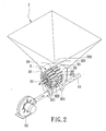
- Figs. 1 and 2 illustrate the preferred embodiment of a feed hopper systemof this invention for receiving and feeding a particulate material to a furnace (not shown) for combustion.
- the feed hopper system includes: a hopper 2 defining a chamber 21 adapted to receive the particulate material therein, the chamber 21 having a lower portion 22; a stirring member 42 extending through the lower portion 22 of the chamber 21 of the hopper 2 for stirring the particulate material; and a rotary feeding member 3 disposed below the stirring member 42, mounted rotatably in the lower portion 22 of the chamber 21 of the hopper 2, and including a rotor 30 that is rotatable relative to the hopper 2 and that has first and second axial end portions 301, 302 .
- the rotary feeding member 3 further includes a plurality of angularly spaced apart first blades 32 that radiate from the first axial end portion 301 of the rotor 30, and a plurality of angularly spaced apart second blades 33 that radiate from the second axial end portion 302 of the rotor 30.
- the first and second blades 32,33 are alternately disposed (see Fig. 3 ).
- the feed hopper system further includes a driving shaft 31 extending through the lower portion 22 of the chamber 21.
- the rotor 30 is sleeved securely on and is driven by the driving shaft 31.
- the rotary feeding member 3 further includes a partitioning plate 34 that radiates from the rotor 30 and that separates the first blades 32 from the second blades 33.
- Each of the first and second blades 32,33 includes a rigid plate 321,331 that has a free end 3211,3311, and an elastic pad 322,332 attached to the free end 3211,3311 of the rigid plate 321,331.
- the lower portion 22 of the chamber 21 of the hopper 2 is defined by a lower wall portion 23 of the hopper 2.
- the elastic pad 322,332 of each of the first and second blades 32,33 is in sliding contact with the lower wall portion 23 of the hopper 2.
- a motor 41 is connected to the driving shaft 31 for driving the stirring member 42 and the rotary feeding member 3.
- the driving shaft 31 is connected to a shaft 421 of the stirring member 42 through a transmission unit 43 so as to permit co-rotation of the stirring member 42 and the rotary feeding member 3.
- a feed conveying tube 51 is connected to the lower portion 22 of the chamber 21 of the hopper 2.
- a blower 52 is connected to the feed conveying tube 51.
- the stirring member 42 and the rotary feeding member 3 are driven to rotate, and the particulate material is carried from the chamber 21 of the hopper 2 into the feed conveying tube 51, and is subsequently carried away by an air flow generated by the blower 52 to the furnace (not shown).
Landscapes
- Engineering & Computer Science (AREA)
- Mechanical Engineering (AREA)
- General Engineering & Computer Science (AREA)
- Life Sciences & Earth Sciences (AREA)
- Environmental Sciences (AREA)
- Birds (AREA)
- Animal Husbandry (AREA)
- Biodiversity & Conservation Biology (AREA)
- Filling Or Emptying Of Bunkers, Hoppers, And Tanks (AREA)
Applications Claiming Priority (1)
| Application Number | Priority Date | Filing Date | Title |
|---|---|---|---|
| TW096210757U TWM323587U (en) | 2007-07-02 | 2007-07-02 | Material feeding device |
Publications (2)
| Publication Number | Publication Date |
|---|---|
| EP2011391A2 true EP2011391A2 (fr) | 2009-01-07 |
| EP2011391A3 EP2011391A3 (fr) | 2009-09-23 |
Family
ID=39460903
Family Applications (1)
| Application Number | Title | Priority Date | Filing Date |
|---|---|---|---|
| EP08010136A Withdrawn EP2011391A3 (fr) | 2007-07-02 | 2008-06-04 | Système de trémie d'alimentation |
Country Status (3)
| Country | Link |
|---|---|
| EP (1) | EP2011391A3 (fr) |
| KR (1) | KR20090004620A (fr) |
| TW (1) | TWM323587U (fr) |
Cited By (7)
| Publication number | Priority date | Publication date | Assignee | Title |
|---|---|---|---|---|
| EP2700892A3 (fr) * | 2012-08-23 | 2017-04-26 | Chai-Long Yu | Appareil de fusion de matériau à base d'aluminium |
| ITUA20164586A1 (it) * | 2016-06-22 | 2017-12-22 | Deref Spa | Apparato di deposizione di polveri in impianti siderurgici |
| CN108775597A (zh) * | 2018-05-17 | 2018-11-09 | 北京国奥天开信息技术有限公司 | 一种用于生物质颗粒炉的下料系统 |
| CN109051816A (zh) * | 2018-07-02 | 2018-12-21 | 芜湖万向新元环保科技有限公司 | 一种节能环保的气力输送装置 |
| CN113207781A (zh) * | 2021-05-24 | 2021-08-06 | 广东海洋大学 | 一种风送式投料机 |
| EP4491362A3 (fr) * | 2023-07-11 | 2025-02-26 | Johann Bergmann GmbH & Co | Procédé et dispositif pour la fabrication de plaques de paille et dispositif d'alimentation en hydrate de chaux pour ce procédé |
| CN121431784A (zh) * | 2025-12-31 | 2026-01-30 | 北京中仪智控科技有限公司 | 一种多品种粮食收购的自动检测装置 |
Families Citing this family (2)
| Publication number | Priority date | Publication date | Assignee | Title |
|---|---|---|---|---|
| KR101354939B1 (ko) * | 2011-12-26 | 2014-01-27 | 재단법인 포항산업과학연구원 | 유동층 연소로용 연료공급장치 |
| KR101413641B1 (ko) * | 2014-02-26 | 2014-08-06 | (주)이파워기술단 | 화력발전소의 과열 증기를 활용한 석탄 건조시스템 |
Family Cites Families (4)
| Publication number | Priority date | Publication date | Assignee | Title |
|---|---|---|---|---|
| US2565546A (en) * | 1947-08-05 | 1951-08-28 | Richard R Colburn | Radial flow rotary feeder for concrete aggregate |
| US4259032A (en) * | 1978-01-18 | 1981-03-31 | Rothmans Of Pall Mall Canada Limited | Air lock |
| FR2506397A1 (fr) * | 1981-05-19 | 1982-11-26 | Sprunck Jules | Pompe distributrice de matiere pulverulente a alveoles |
| EP1006064A1 (fr) * | 1998-12-02 | 2000-06-07 | Waeschle GmbH | Vanne à roue cellulaire |
-
2007
- 2007-07-02 TW TW096210757U patent/TWM323587U/zh not_active IP Right Cessation
-
2008
- 2008-06-04 EP EP08010136A patent/EP2011391A3/fr not_active Withdrawn
- 2008-06-30 KR KR1020080062676A patent/KR20090004620A/ko not_active Ceased
Cited By (8)
| Publication number | Priority date | Publication date | Assignee | Title |
|---|---|---|---|---|
| EP2700892A3 (fr) * | 2012-08-23 | 2017-04-26 | Chai-Long Yu | Appareil de fusion de matériau à base d'aluminium |
| ITUA20164586A1 (it) * | 2016-06-22 | 2017-12-22 | Deref Spa | Apparato di deposizione di polveri in impianti siderurgici |
| CN108775597A (zh) * | 2018-05-17 | 2018-11-09 | 北京国奥天开信息技术有限公司 | 一种用于生物质颗粒炉的下料系统 |
| CN109051816A (zh) * | 2018-07-02 | 2018-12-21 | 芜湖万向新元环保科技有限公司 | 一种节能环保的气力输送装置 |
| CN113207781A (zh) * | 2021-05-24 | 2021-08-06 | 广东海洋大学 | 一种风送式投料机 |
| CN113207781B (zh) * | 2021-05-24 | 2022-11-15 | 广东海洋大学 | 一种风送式投料机 |
| EP4491362A3 (fr) * | 2023-07-11 | 2025-02-26 | Johann Bergmann GmbH & Co | Procédé et dispositif pour la fabrication de plaques de paille et dispositif d'alimentation en hydrate de chaux pour ce procédé |
| CN121431784A (zh) * | 2025-12-31 | 2026-01-30 | 北京中仪智控科技有限公司 | 一种多品种粮食收购的自动检测装置 |
Also Published As
| Publication number | Publication date |
|---|---|
| EP2011391A3 (fr) | 2009-09-23 |
| TWM323587U (en) | 2007-12-11 |
| KR20090004620A (ko) | 2009-01-12 |
Similar Documents
| Publication | Publication Date | Title |
|---|---|---|
| EP2011391A2 (fr) | Système de trémie d'alimentation | |
| US20090057350A1 (en) | Feed hopper system | |
| EP2778292B1 (fr) | Godet de grille de tamis motorisés lourds | |
| CN1880207A (zh) | 纸币积存输出装置 | |
| CN105765356A (zh) | 组合称重装置 | |
| JP6842211B1 (ja) | 飼料搬送装置 | |
| CN103447240A (zh) | 异物分选机 | |
| CN209480617U (zh) | 一种铆钉震动传输装置 | |
| CN109937898B (zh) | 喂食设备 | |
| JP2018130827A (ja) | 生コンクリートの放出装置 | |
| JP4926909B2 (ja) | 穀粒選別装置 | |
| CN216775463U (zh) | 播撒机构和无人设备 | |
| KR101047808B1 (ko) | 경사형 패각분쇄기 | |
| JP2009095732A5 (fr) | ||
| CN218655442U (zh) | 一种煤矿筛分机振动给料装置 | |
| CN106122058B (zh) | 一种蜗壳面板可换的送料风机 | |
| CN210580462U (zh) | 一种宠物喂食器 | |
| CN203725193U (zh) | 一种双笼式破磨机 | |
| RU93301U1 (ru) | Устройство для дробления сыпучих материалов | |
| CN215286906U (zh) | 一种双下料的饲喂器 | |
| EP2981490A1 (fr) | Tube d'alimentation et procédé associé à un tube d'alimentation | |
| CN211811853U (zh) | 一种可调节输送距离的绞龙输送装置 | |
| CN220412193U (zh) | 一种粉末自动喂料装置 | |
| CN109964835A (zh) | 喂养设备 | |
| JP6489962B2 (ja) | スラリーポンプ |
Legal Events
| Date | Code | Title | Description |
|---|---|---|---|
| PUAI | Public reference made under article 153(3) epc to a published international application that has entered the european phase |
Free format text: ORIGINAL CODE: 0009012 |
|
| AK | Designated contracting states |
Kind code of ref document: A2 Designated state(s): AT BE BG CH CY CZ DE DK EE ES FI FR GB GR HR HU IE IS IT LI LT LU LV MC MT NL NO PL PT RO SE SI SK TR |
|
| AX | Request for extension of the european patent |
Extension state: AL BA MK RS |
|
| PUAL | Search report despatched |
Free format text: ORIGINAL CODE: 0009013 |
|
| AK | Designated contracting states |
Kind code of ref document: A3 Designated state(s): AT BE BG CH CY CZ DE DK EE ES FI FR GB GR HR HU IE IS IT LI LT LU LV MC MT NL NO PL PT RO SE SI SK TR |
|
| AX | Request for extension of the european patent |
Extension state: AL BA MK RS |
|
| RIC1 | Information provided on ipc code assigned before grant |
Ipc: F27D 3/18 20060101ALI20090817BHEP Ipc: F27D 3/10 20060101ALI20090817BHEP Ipc: A01K 5/02 20060101AFI20081003BHEP |
|
| AKX | Designation fees paid | ||
| STAA | Information on the status of an ep patent application or granted ep patent |
Free format text: STATUS: THE APPLICATION IS DEEMED TO BE WITHDRAWN |
|
| 18D | Application deemed to be withdrawn |
Effective date: 20100324 |
|
| REG | Reference to a national code |
Ref country code: DE Ref legal event code: 8566 |