EP2011688B1 - Adaptateur pour un système d'arrêt de véhicule automobile - Google Patents
Adaptateur pour un système d'arrêt de véhicule automobile Download PDFInfo
- Publication number
- EP2011688B1 EP2011688B1 EP08011495A EP08011495A EP2011688B1 EP 2011688 B1 EP2011688 B1 EP 2011688B1 EP 08011495 A EP08011495 A EP 08011495A EP 08011495 A EP08011495 A EP 08011495A EP 2011688 B1 EP2011688 B1 EP 2011688B1
- Authority
- EP
- European Patent Office
- Prior art keywords
- casing
- rotary element
- hook
- adapter according
- adapter
- Prior art date
- Legal status (The legal status is an assumption and is not a legal conclusion. Google has not performed a legal analysis and makes no representation as to the accuracy of the status listed.)
- Not-in-force
Links
- 238000002347 injection Methods 0.000 claims 1
- 239000007924 injection Substances 0.000 claims 1
- 238000007373 indentation Methods 0.000 abstract 1
- 238000006073 displacement reaction Methods 0.000 description 8
- 238000003780 insertion Methods 0.000 description 5
- 230000037431 insertion Effects 0.000 description 5
- 238000000926 separation method Methods 0.000 description 3
- 230000006835 compression Effects 0.000 description 1
- 238000007906 compression Methods 0.000 description 1
- 230000003247 decreasing effect Effects 0.000 description 1
- 230000009977 dual effect Effects 0.000 description 1
- 230000000694 effects Effects 0.000 description 1
- 239000000463 material Substances 0.000 description 1
- 239000007769 metal material Substances 0.000 description 1
- 238000000034 method Methods 0.000 description 1
Images

Classifications
-
- B—PERFORMING OPERATIONS; TRANSPORTING
- B60—VEHICLES IN GENERAL
- B60P—VEHICLES ADAPTED FOR LOAD TRANSPORTATION OR TO TRANSPORT, TO CARRY, OR TO COMPRISE SPECIAL LOADS OR OBJECTS
- B60P7/00—Securing or covering of load on vehicles
- B60P7/06—Securing of load
- B60P7/135—Securing or supporting by load bracing means
- B60P7/15—Securing or supporting by load bracing means the load bracing means comprising a movable bar
-
- B—PERFORMING OPERATIONS; TRANSPORTING
- B60—VEHICLES IN GENERAL
- B60P—VEHICLES ADAPTED FOR LOAD TRANSPORTATION OR TO TRANSPORT, TO CARRY, OR TO COMPRISE SPECIAL LOADS OR OBJECTS
- B60P7/00—Securing or covering of load on vehicles
- B60P7/06—Securing of load
- B60P7/08—Securing to the vehicle floor or sides
- B60P7/0807—Attachment points
- B60P7/0815—Attachment rails or trellis
Definitions
- the invention relates to an adapter for a motor vehicle holding system according to the preamble of patent claim 1.
- an adapter for a motor vehicle holding system in the region of a trunk of the motor vehicle which has a housing and clamping elements, so that the housing can be fixed in a clamping position on a mounting rail mounted on the motor vehicle.
- the adapter has an O-shaped lashing strap, so that cargo can be lashed down using belts.
- an adapter for fixing conveyed to a mounted in a motor vehicle retaining rail is known.
- a locking pin which engages in a recess of the mounting rail and thus fixes the adapter.
- the adapter also has a recess on, which serves to receive a vertical rod of the conveyed.
- an insertion opening is formed, wherein the insertion opening can be at least partially closed by means of a clamping lever.
- Object of the present invention is to develop an adapter for a motor vehicle-holding system such that the handling or ease of use with respect to the attachment of luggage racks, nets, bags and the like improved.
- the invention has the features of claim 1.
- the particular advantage of the invention is that the provision of mounting options on the adapter is improved by providing a pivotable functional hook.
- a clamping position of the adapter of the function hooks can be swung out of an extension plane of a housing of the adapter, so that the mounting location of fasteners, such as belt, rods, etc. of the same in the clamping position of the adapter is changeable. This increases the variability of the adapter with respect to the attachment or fixing of fasteners on the same.
- the invention has a spatial separation between a manually operable rotary member, by means of which the adapter can be brought into the clamping position and in the non-clamping position, and the function hook, so that easy to use a defined spatial separation between the Actuating means for fixing the adapter to the support rail of the motor vehicle on the one hand and for fixing fasteners on the adapter on the other hand is given.
- the adapter can be manipulated by means of the insertable into the recess of the rotary member holding rod.
- the adapter has a slot for a belt receiving, which extends in extension to a pivot axis about which the functional hook is pivotable.
- the slot thus forms a spatial separation between the central portion of the housing in which the rotary member is located, and an outer portion of the housing in which the function hook is located.
- the slot can be arranged to save space.
- the support rod is connected via a ball joint with the knob, so that the support rod is easy to use by pivoting about the pivot point of the ball joint in a three-dimensional space can be aligned.
- the housing is integrally connected in a adjacent to the rotary member lower portion with a hook on which the support rod is detachably connected.
- a further functional component is provided for connection to fastening means designed as a holding rod.
- the invention thus makes it possible to provide functional components for fixing fastening means over the entire surface of a housing of the adapter.
- a central portion of the housing can be mounted at different heights a holding rod.
- an outer section of the housing can be added at different heights straps, nets or bags are hung.
- the function hook is fixed in the folded-in position in which it runs along the plane of extent of the housing, and in the unfolded position in which it is at an angle to the plane of extension of the housing.
- one or more defined Festlegpositionen be specified.
- the function hook on the edge side at least one support end and / or a rotation stop, so that the function hook is obtained in the retracted position and in the unfolded position respectively in a defined position to the housing.
- the rotary member is movable about a plane perpendicular to the extension plane of the housing axis of rotation, wherein the rotary member for moving the housing in the clamping position acting on adjusting means such that in a rotational position of the rotary element, a first clamping element in the transverse direction to the axis of rotation of the rotary member presses against the retaining rail and a second clamping element in the axial direction of the rotary member presses against the retaining rail.
- this can be done by the adapter along the support rail without applying a holding force of a clamping element counteracting force.
- the clamping element In the displacement position of the adapter, the clamping element is only in an abutment position on the retaining rail, without a clamping force acting on the retaining rail.
- Easy to use the movement of the adapter from a displacement position into a clamping position and vice versa by rotating the rotary member about a rotation axis can be effected, wherein the rotation axis is perpendicular to the support rail.
- clamping elements act in the transverse direction to the axis of rotation of the rotary member and in the axial direction of the rotary member, a secure fixation of the adapter can be effected in the clamping position.
- An inventive adapter 1 is used for attachment of handrails 2, luggage racks, nets, bags and the like on a support rail 3, which is mounted in a luggage compartment of a motor vehicle on an upright inner wall.
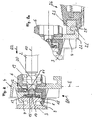
- the adapter 1 has a substantially plate-shaped housing 4, which is mounted in a central portion 5 by means of a rotary member 6 releasably and slidably on the double-T-retaining rail 3.
- the housing 4 has a pincer-shaped projection 7, which is placed around a protruding from the body wall of the motor vehicle front portion of the support rail 3.
- a detent element 8 designed as a clamping element with its nose 9, the narrow side of the front portion of the support rail.
- the rotary member 6 is formed as a trained as an actuator knob, which is about an axis of rotation 10th is mounted in the housing 4.
- the knob 6 is rotatably connected to an eccentric 11 having a circumferentially extending eccentric surface.
- the eccentric Upon rotation of the knob 6 from a displacement position in a clamping position, for example, 45 °, the eccentric exerts a force on a leaf spring 12, so that the latching hook 8 is moved in a first transverse direction Q1 laterally to the support rail 3 in the clamping position and thus the housing 4 clamped to the support rail 3.
- the eccentric 11 has an axially extending cam 13, which acts upon rotation of the knob 6 in a second transverse direction Q2 on an axially displaceable pressure member 14 which acts on a resiliently in the axial direction of pressure plate 15 (further clamping element).
- the pressure plate 15 is thus pressed in the clamping position on an upper side or flat side of the retaining rail 3. Since the pressure plate 15 is resiliently designed in the region of the pressure piece 14, this process can always be repeated without the clamping force on the holding rail 3 decreasing.
- the knob 6 is in a zero position in which the clear distance between the projection 7 of the housing 4 and the nose 9 of the latching hook 8 is greater than the transverse extent of the front portion of the support rail 3rd Auf In this way, the adapter 1 can be placed on the support rail 3 and spent by rotation of the knob 6 by 45 ° in a displacement position in which the nose 9 of the latching hook 8 engages behind the front portion of the support rail 3 and the adapter 1 along the support rail. 3 is displaceable.
- the knob 6 has reached the displacement position when by means of a head of the knob 6 in a recess mounted detent sleeve 16 by means of a compression spring, not shown in a recess of the housing 4 engages and thus locks the knob 6.
- the eccentric 11 serves as Drehzisumwandlungsorgan, the circumferential eccentric surfaces serve as a transverse movement connection for acting on the latching hook 8 and the cam 13 as Axialmonysan gleich for acting on the pressure member 14.
- the nose 9 of the latching hook 8 is only on the support rail 3, without exerting a clamping force.
- the pressure plate 15 is also in this displacement position without clamping effect on the support rail 3, wherein a corrugated plate 18 between the pressure plate 15 and the pressure member 14 provides for a tolerance compensation.
- the rotary element 6 serves as a functional part, since it has a recess 19 into which a head 20 provided with an end of the support rod 2 can engage, so that the support rod 2 is connected via a ball joint with the rotary member 6.
- the support rod 2 can thus be pivoted in the mounting position in the horizontal and / or vertical direction about a center of the head 20.
- the rotary element 6 thus has a dual function. On the one hand, it serves to lock the adapter 1 to the support rail 3 and the other to receive one end of the support rod 2.
- a hook 22 is arranged as a functional part, which is positively connected with a hook-shaped end 23 of a support rod 24, in particular latching.
- the support rod 24 For mounting the support rod 24 to the housing 4, the same is suspended by partially engaging around an end 22 'of the hook 22 through the hook-shaped end 23 and locked by engaging behind a spring-biased clamping member 25 of the support rod 24 to the hook 22.
- the hook 22 protrudes from the housing 4 on a side facing away from the retaining rail 3 and extends substantially below the rotary element 6.
- a respective fastening hook 27 is arranged as a functional part, which extends rigidly in an extension plane E of the housing 4.
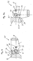
- a pivotable function hook 28 is in each case arranged around a pivot axis 29 from a folded position S1 in accordance with FIG. 3 in which it is located in the extension plane E of the housing 4, in an unfolded position S2 according to FIG FIG. 3a is pivotable, in which the function hook 28 is at an angle to the plane of extension E of the housing 4.
- the function hook 28 is fixed in the folded position S1 and in the unfolded position S2 detent.
- the function hook 28 has two offset by the pivot angle ⁇ and arranged at an equal distance A to the pivot axis 29 first recess 30 and second recess 31, in each of the retracted position S1 and in the unfolded position S2 is a spring-biased and latching engages in a bore 33 of the housing 4 mounted bolt 32.
- the axis of the bolt 32 is arranged parallel to the pivot axis 29. Since the first recess 30 and the second recess 31 are arranged at a right angle offset from the pivot axis 29, the pivot angle ⁇ in the present embodiment is 90 °.
- the swivel angle can also be larger or smaller, or several swivel angles can be specified by increasing the number of recesses.
- the function hook 28 is supported in the retracted position S1 by means of a Supporting 34 surface on a rear part 35 'of a wall 35 of the housing 4 from.
- the functional hook 28 is in the unfolded position S2 via a rotation stopper 36 on a front part 35 "of the wall 35.
- Advantageously defined end positions of the functional hook 28 can thus be effected.
- the pivot axis 29 is arranged perpendicular to the axis of rotation 10.
- the pivot axis 29 is arranged perpendicular to a longitudinal center plane L of the housing 4.
- a slot 38 is provided in a region between the central portion 5 and the outer portion 26 for receiving a belt.
- the slot 38 thus serves as another functional part for attachment of luggage etc.
- the slot 38 extends over half the height of the housing 4 and allows the insertion of a strap, not shown, easy to use from an upper side of the housing 4 ago.
- the spring-biased pin 32 engages with its dome 40 in the first recess 30.
- the function hook 28 is clipped with its shaft 41 and its collar 42 in the housing 4 and rotatably mounted in a bore 43. Above this bore 43, the slot 38 extends to receive a belt.
- the adapter 1 may be made of a plastic or a metal material.
Landscapes
- Engineering & Computer Science (AREA)
- Transportation (AREA)
- Mechanical Engineering (AREA)
- Motor Or Generator Frames (AREA)
- Hooks, Suction Cups, And Attachment By Adhesive Means (AREA)
- Arrangement Or Mounting Of Propulsion Units For Vehicles (AREA)
- Load-Engaging Elements For Cranes (AREA)
- Fittings On The Vehicle Exterior For Carrying Loads, And Devices For Holding Or Mounting Articles (AREA)
- Clamps And Clips (AREA)
Claims (15)
- Adaptateur (1) pour un système de support dans un véhicule automobile, prévu dans la zone d'un coffre dudit véhicule automobile, avec un boîtier (4), qui peut être fixé, dans une position de blocage, sur un rail de maintien (3) monté sur le véhicule automobile, un l'élément rotatif (6), au moyen duquel le boîtier (4) peut être amené dans la position de blocage, étant monté à rotation sur ledit boîtier (4), l'élément rotatif (6) présentant des moyens pour la liaison amovible d'une barre de maintien (2), caractérisé en ce que le moyen de liaison amovible de la barre de maintien (2) est réalisé sous la forme d'une cavité (19) de l'élément rotatif (6), dans laquelle la barre de maintien (2) peut être introduite de sorte que l'élément rotatif (6) puisse être amené, au moyen de la barre de maintien (2), dans la position de blocage, dans laquelle l'adapteur (1) est fixé sur le rail de maintien (3), et / ou dans une position de déplacement, dans laquelle le boitier (4) peut être déplacé avec la barre de maintien (2) le long du rail de maintien (3), et en ce que le boîtier (4) est relié à un crochet fonctionnel (28), qui peut pivoter autour d'un axe de pivotement (29).
- Adaptateur selon la revendication 1, caractérisé en ce que le boîtier (4) présente une fente (38) pour la réception d'une sangle, ladite fente (38) s'étendant dans le prolongement de l'axe de pivotement (29) du crochet fonctionnel (28).
- Adaptateur selon revendication 1 ou 2, caractérisé en ce que l'élément rotatif (6) comprend un bouton rotatif, qui est pourvu de la cavité (19).
- Adaptateur selon l'une des revendications 1 à 3, caractérisé en ce que la cavité (19) de l'élément rotatif (6) est configurée de sorte qu'une extrémité de la barre de maintien (2) soit reliée, solidaire en rotation, à l'élément rotatif (6), par l'intermédiaire d'une articulation à rotule.
- Adaptateur selon l'une des revendications 1 à 4, caractérisé en ce que le boîtier (4) comprend, dans une section centrale (5), dans une région inférieure (21), un crochet (22), qui, étant relié d'une pièce à celui-ci, est disposé sur un côté du boîtier (4), opposé au rail de maintien (3), et qui peut être relié de manière amovible à la barre de maintien (2).
- Adaptateur selon la revendication 5, caractérisé en ce que le crochet (22) est réalisé par injection sur le boîtier (4) et que la barre de maintien (2) peut être suspendue au crochet (22) et verrouillée.
- Adaptateur selon l'une des revendications 1 à 6, caractérisé en ce que le crochet fonctionnel pivotant (28) peut pivoter autour d'un axe de pivotement (29), perpendiculaire au plan médian longitudinal (L) du boîtier (4), entre une position repliée (S1), dans laquelle le crochet de fixation (8) s'étend sur un plan de projection (E) du boîtier (4) et une position dépliée (S2), dans laquelle le crochet fonctionnel (28) est tourné sur un angle par rapport au plan de projection (E) du boîtier (4).
- Adaptateur selon l'une des revendications 1 à 7, caractérisé en ce que le crochet fonctionnel (28) est fixé par enclenchement dans la position repliée (S1) et dans la position dépliée (S2), un boulon (32) du boîtier (4), sollicité par ressort, s'engageant chaque fois dans un évidement (30, 31) du crochet fonctionnel (28).
- Adaptateur selon l'une des revendications 1 à 8, caractérisé en ce que le boulon sollicité par ressort (32) est disposé parallèlement à l'axe de pivotement (29).
- Adaptateur selon l'une des revendications 1 à 9, caractérisé en ce que les évidements (30, 31) du crochet fonctionnel (8) et le boulon sollicité par ressort (32) sont disposés à la même distance (A) de l'axe de pivotement (29) et qu'un premier évidement (30) et un deuxième évidement (31) du crochet fonctionnel (28) sont disposés, décalés à angle droit autour de l'axe de pivotement (29).
- Adaptateur selon l'une des revendications 1 à 10,
caractérisé en ce que le crochet fonctionnel (28) présente une extrémité d'appui (34), qui, dans la position repliée (S1) s'appuie à plat sur la partie arrière (35') d'une paroi (35) du boîtier (4). - Adaptateur selon l'une des revendications 1 à 11,
caractérisé en ce que le crochet fonctionnel (28) présente une butée tournante (36), qui, dans la position dépliée (S2), s'appuie à plat sur une partie avant (35") de la paroi (35) du boîtier (4). - Adaptateur selon l'une des revendications 1 à 12, caractérisé en ce que l'élément rotatif (6) peut être déplacé autour d'un axe de pivotement (10), qui s'étend perpendiculairement au plan de projection (E) du boîtier (4), que, pour amener le boîtier (4) dans la position de blocage, l'élément rotatif (6) agit sur des moyens de blocage (8, 15) de sorte que, dans une position de rotation de l'élément rotatif (6), un premier élément de blocage (8) appuie contre le rail de maintien (3), dans la direction perpendiculaire à l'axe de rotation (10), et qu'un deuxième élément de blocage (15) appuie contre le rail de maintien (3) dans la direction axiale de l'élément rotatif (6).
- Adaptateur selon l'une des revendications 1 à 13, caractérisé en ce que les moyens de blocage (8, 15) comprennent un organe de conversion du mouvement de rotation (11), qui est relié, solidaire en rotation, à l'élément rotatif (6), et qui, d'une part, présente un raccord de mouvement transversal, qui agit sur le premier élément de blocage (8) et, d'autre part, un raccord de mouvement axial (17), qui agit sur le deuxième élément de blocage (15).
- Adaptateur selon l'une des revendications 1 à 14, caractérisé en ce que le raccord de mouvement transversal est réalisé sous la forme d'une surface d'excentrique de l'excentrique (11), qui s'étend dans la direction périphérique.
Applications Claiming Priority (1)
| Application Number | Priority Date | Filing Date | Title |
|---|---|---|---|
| DE102007030913 | 2007-07-03 |
Publications (2)
| Publication Number | Publication Date |
|---|---|
| EP2011688A1 EP2011688A1 (fr) | 2009-01-07 |
| EP2011688B1 true EP2011688B1 (fr) | 2010-05-19 |
Family
ID=39864968
Family Applications (1)
| Application Number | Title | Priority Date | Filing Date |
|---|---|---|---|
| EP08011495A Not-in-force EP2011688B1 (fr) | 2007-07-03 | 2008-06-25 | Adaptateur pour un système d'arrêt de véhicule automobile |
Country Status (4)
| Country | Link |
|---|---|
| EP (1) | EP2011688B1 (fr) |
| AT (1) | ATE468252T1 (fr) |
| DE (1) | DE502008000673D1 (fr) |
| PT (1) | PT2011688E (fr) |
Families Citing this family (3)
| Publication number | Priority date | Publication date | Assignee | Title |
|---|---|---|---|---|
| DE102011112115A1 (de) * | 2011-09-02 | 2013-03-07 | GM Global Technology Operations LLC (n. d. Gesetzen des Staates Delaware) | Schiene zur Lagerung eines Funktionsteils in einem Innenraum eines Kraftfahrzeugs |
| FR3000926B1 (fr) * | 2013-01-17 | 2016-07-01 | Jean Chereau Sas | Systeme de support et/ou d'arrimage de marchandises, notamment pour vehicule routier de transport |
| DE102014113930A1 (de) * | 2014-09-25 | 2016-03-31 | Allsafe Jungfalk Gmbh & Co. Kg | Vorrichtung zum Festlegen von Ladungsgegenständen |
Family Cites Families (6)
| Publication number | Priority date | Publication date | Assignee | Title |
|---|---|---|---|---|
| US6382891B1 (en) * | 2001-04-24 | 2002-05-07 | William B. Bellis, Jr. | Tie down |
| DE10134887B4 (de) * | 2001-07-18 | 2006-01-19 | Daimlerchrysler Ag | Befestigungsvorrichtung zum Haltern und/oder Sichern von Gegenständen in einem Fahrzeugladeraum |
| DE10236077B4 (de) * | 2002-08-07 | 2009-12-24 | GM Global Technology Operations, Inc., Detroit | Befestigungssystem für Zubehörteile |
| DE20302929U1 (de) * | 2003-02-21 | 2003-07-17 | ANCRA Jungfalk GmbH & Co. KG, 78234 Engen | Vorrichtung zur Sicherung von Ladegütern |
| US20060263163A1 (en) * | 2003-04-16 | 2006-11-23 | Harberts John H | Securement mechanism |
| DE202006010599U1 (de) | 2005-07-14 | 2006-10-05 | Ymos Gmbh | Verzurrvorrichtung |
-
2008
- 2008-06-25 PT PT08011495T patent/PT2011688E/pt unknown
- 2008-06-25 DE DE502008000673T patent/DE502008000673D1/de active Active
- 2008-06-25 AT AT08011495T patent/ATE468252T1/de active
- 2008-06-25 EP EP08011495A patent/EP2011688B1/fr not_active Not-in-force
Also Published As
| Publication number | Publication date |
|---|---|
| EP2011688A1 (fr) | 2009-01-07 |
| ATE468252T1 (de) | 2010-06-15 |
| PT2011688E (pt) | 2010-07-23 |
| DE502008000673D1 (de) | 2010-07-01 |
Similar Documents
| Publication | Publication Date | Title |
|---|---|---|
| DE3701341C2 (fr) | ||
| DE19654395C1 (de) | Nocken zur lösbaren Verriegelung eines Bauteils, insbesondere an einem Kraftfahrzeugsitz | |
| DE202009014811U1 (de) | Möbelbeschlag zum lösbaren Verbinden zweier Möbelteile | |
| DE10008277B4 (de) | Schließvorrichtung | |
| DE202006003411U1 (de) | Geräteträger mti biegbarem austauschbarem Tragarm | |
| DE2945950A1 (de) | Spannkrallenbefestigung zum anbringen eines dachgepaecktraegers an einem kraftwagen | |
| EP2011688B1 (fr) | Adaptateur pour un système d'arrêt de véhicule automobile | |
| DE3224014C2 (fr) | ||
| DE19836473B4 (de) | Windstopeinrichtung | |
| DE102010011086A1 (de) | Anordnung mindestens eines Funktionsmoduls auf einem Fahrzeugboden eines Fahrzeugs | |
| DE19812490C2 (de) | Einrichtung zur lösbaren Befestigung eines Sitzes, insbesondere Fahrzeugsitzes, an einer längsverlaufenden Schiene | |
| DE1784610C3 (de) | Schnellbefestigungseinrichtung für ein Arbeitsgerät | |
| DE29507584U1 (de) | Antennenbefestigung | |
| WO2017032353A1 (fr) | Système de retenue et/ou de blocage | |
| DE1653947B2 (fr) | ||
| EP1645467B1 (fr) | Dispositif de fixation pour une lampe et procédé d'assemblage | |
| EP1568540B1 (fr) | Dispositif d'amarrage de Bagages dans un véhicule | |
| DE19745928C2 (de) | Türfeststeller an einer Kraftfahrzeugtür | |
| EP1932719B1 (fr) | Dispositif de retenue pour tronçons de bagages | |
| EP2168809B1 (fr) | Dispositif de fixation destiné à la fixation de tronçons de bagages | |
| WO1999051843A1 (fr) | Plaque de montage pour charnieres de meubles | |
| DE212010000167U1 (de) | Selbst-verriegelndes Kraftfahrzeugzubehör für ein Fahrzeugkarosserieteil | |
| DE10228046B4 (de) | Halterungsöse für ein Verzurrmittel zum Sichern von Ladegut in einem Fahrzeug | |
| EP2538094B1 (fr) | Crochet de mousqueton | |
| AT403617B (de) | Verbindungsbeschlag zum lösbaren verbinden zweier möbelteile |
Legal Events
| Date | Code | Title | Description |
|---|---|---|---|
| PUAI | Public reference made under article 153(3) epc to a published international application that has entered the european phase |
Free format text: ORIGINAL CODE: 0009012 |
|
| AK | Designated contracting states |
Kind code of ref document: A1 Designated state(s): AT BE BG CH CY CZ DE DK EE ES FI FR GB GR HR HU IE IS IT LI LT LU LV MC MT NL NO PL PT RO SE SI SK TR |
|
| AX | Request for extension of the european patent |
Extension state: AL BA MK RS |
|
| 17P | Request for examination filed |
Effective date: 20090608 |
|
| 17Q | First examination report despatched |
Effective date: 20090729 |
|
| AKX | Designation fees paid |
Designated state(s): AT BE BG CH CY CZ DE DK EE ES FI FR GB GR HR HU IE IS IT LI LT LU LV MC MT NL NO PL PT RO SE SI SK TR |
|
| GRAP | Despatch of communication of intention to grant a patent |
Free format text: ORIGINAL CODE: EPIDOSNIGR1 |
|
| GRAS | Grant fee paid |
Free format text: ORIGINAL CODE: EPIDOSNIGR3 |
|
| GRAA | (expected) grant |
Free format text: ORIGINAL CODE: 0009210 |
|
| AK | Designated contracting states |
Kind code of ref document: B1 Designated state(s): AT BE BG CH CY CZ DE DK EE ES FI FR GB GR HR HU IE IS IT LI LT LU LV MC MT NL NO PL PT RO SE SI SK TR |
|
| REG | Reference to a national code |
Ref country code: GB Ref legal event code: FG4D Free format text: NOT ENGLISH |
|
| REG | Reference to a national code |
Ref country code: CH Ref legal event code: EP |
|
| REG | Reference to a national code |
Ref country code: IE Ref legal event code: FG4D Free format text: LANGUAGE OF EP DOCUMENT: GERMAN |
|
| REF | Corresponds to: |
Ref document number: 502008000673 Country of ref document: DE Date of ref document: 20100701 Kind code of ref document: P |
|
| REG | Reference to a national code |
Ref country code: PT Ref legal event code: SC4A Free format text: AVAILABILITY OF NATIONAL TRANSLATION Effective date: 20100716 |
|
| REG | Reference to a national code |
Ref country code: SE Ref legal event code: TRGR |
|
| REG | Reference to a national code |
Ref country code: NL Ref legal event code: VDEP Effective date: 20100519 |
|
| LTIE | Lt: invalidation of european patent or patent extension |
Effective date: 20100519 |
|
| PG25 | Lapsed in a contracting state [announced via postgrant information from national office to epo] |
Ref country code: NO Free format text: LAPSE BECAUSE OF FAILURE TO SUBMIT A TRANSLATION OF THE DESCRIPTION OR TO PAY THE FEE WITHIN THE PRESCRIBED TIME-LIMIT Effective date: 20100819 Ref country code: ES Free format text: LAPSE BECAUSE OF FAILURE TO SUBMIT A TRANSLATION OF THE DESCRIPTION OR TO PAY THE FEE WITHIN THE PRESCRIBED TIME-LIMIT Effective date: 20100830 Ref country code: LT Free format text: LAPSE BECAUSE OF FAILURE TO SUBMIT A TRANSLATION OF THE DESCRIPTION OR TO PAY THE FEE WITHIN THE PRESCRIBED TIME-LIMIT Effective date: 20100519 |
|
| PG25 | Lapsed in a contracting state [announced via postgrant information from national office to epo] |
Ref country code: SI Free format text: LAPSE BECAUSE OF FAILURE TO SUBMIT A TRANSLATION OF THE DESCRIPTION OR TO PAY THE FEE WITHIN THE PRESCRIBED TIME-LIMIT Effective date: 20100519 Ref country code: LV Free format text: LAPSE BECAUSE OF FAILURE TO SUBMIT A TRANSLATION OF THE DESCRIPTION OR TO PAY THE FEE WITHIN THE PRESCRIBED TIME-LIMIT Effective date: 20100519 Ref country code: IS Free format text: LAPSE BECAUSE OF FAILURE TO SUBMIT A TRANSLATION OF THE DESCRIPTION OR TO PAY THE FEE WITHIN THE PRESCRIBED TIME-LIMIT Effective date: 20100919 Ref country code: HR Free format text: LAPSE BECAUSE OF FAILURE TO SUBMIT A TRANSLATION OF THE DESCRIPTION OR TO PAY THE FEE WITHIN THE PRESCRIBED TIME-LIMIT Effective date: 20100519 Ref country code: FI Free format text: LAPSE BECAUSE OF FAILURE TO SUBMIT A TRANSLATION OF THE DESCRIPTION OR TO PAY THE FEE WITHIN THE PRESCRIBED TIME-LIMIT Effective date: 20100519 |
|
| BERE | Be: lapsed |
Owner name: YMOS G.M.B.H. Effective date: 20100630 |
|
| PG25 | Lapsed in a contracting state [announced via postgrant information from national office to epo] |
Ref country code: CY Free format text: LAPSE BECAUSE OF FAILURE TO SUBMIT A TRANSLATION OF THE DESCRIPTION OR TO PAY THE FEE WITHIN THE PRESCRIBED TIME-LIMIT Effective date: 20100609 Ref country code: PL Free format text: LAPSE BECAUSE OF FAILURE TO SUBMIT A TRANSLATION OF THE DESCRIPTION OR TO PAY THE FEE WITHIN THE PRESCRIBED TIME-LIMIT Effective date: 20100519 |
|
| REG | Reference to a national code |
Ref country code: IE Ref legal event code: FD4D |
|
| PG25 | Lapsed in a contracting state [announced via postgrant information from national office to epo] |
Ref country code: IE Free format text: LAPSE BECAUSE OF FAILURE TO SUBMIT A TRANSLATION OF THE DESCRIPTION OR TO PAY THE FEE WITHIN THE PRESCRIBED TIME-LIMIT Effective date: 20100519 Ref country code: NL Free format text: LAPSE BECAUSE OF FAILURE TO SUBMIT A TRANSLATION OF THE DESCRIPTION OR TO PAY THE FEE WITHIN THE PRESCRIBED TIME-LIMIT Effective date: 20100519 Ref country code: MC Free format text: LAPSE BECAUSE OF NON-PAYMENT OF DUE FEES Effective date: 20100630 Ref country code: EE Free format text: LAPSE BECAUSE OF FAILURE TO SUBMIT A TRANSLATION OF THE DESCRIPTION OR TO PAY THE FEE WITHIN THE PRESCRIBED TIME-LIMIT Effective date: 20100519 Ref country code: DK Free format text: LAPSE BECAUSE OF FAILURE TO SUBMIT A TRANSLATION OF THE DESCRIPTION OR TO PAY THE FEE WITHIN THE PRESCRIBED TIME-LIMIT Effective date: 20100519 |
|
| PG25 | Lapsed in a contracting state [announced via postgrant information from national office to epo] |
Ref country code: SK Free format text: LAPSE BECAUSE OF FAILURE TO SUBMIT A TRANSLATION OF THE DESCRIPTION OR TO PAY THE FEE WITHIN THE PRESCRIBED TIME-LIMIT Effective date: 20100519 Ref country code: RO Free format text: LAPSE BECAUSE OF FAILURE TO SUBMIT A TRANSLATION OF THE DESCRIPTION OR TO PAY THE FEE WITHIN THE PRESCRIBED TIME-LIMIT Effective date: 20100519 Ref country code: CZ Free format text: LAPSE BECAUSE OF FAILURE TO SUBMIT A TRANSLATION OF THE DESCRIPTION OR TO PAY THE FEE WITHIN THE PRESCRIBED TIME-LIMIT Effective date: 20100519 |
|
| PLBE | No opposition filed within time limit |
Free format text: ORIGINAL CODE: 0009261 |
|
| STAA | Information on the status of an ep patent application or granted ep patent |
Free format text: STATUS: NO OPPOSITION FILED WITHIN TIME LIMIT |
|
| PG25 | Lapsed in a contracting state [announced via postgrant information from national office to epo] |
Ref country code: IT Free format text: LAPSE BECAUSE OF FAILURE TO SUBMIT A TRANSLATION OF THE DESCRIPTION OR TO PAY THE FEE WITHIN THE PRESCRIBED TIME-LIMIT Effective date: 20100519 |
|
| 26N | No opposition filed |
Effective date: 20110222 |
|
| PG25 | Lapsed in a contracting state [announced via postgrant information from national office to epo] |
Ref country code: MT Free format text: LAPSE BECAUSE OF FAILURE TO SUBMIT A TRANSLATION OF THE DESCRIPTION OR TO PAY THE FEE WITHIN THE PRESCRIBED TIME-LIMIT Effective date: 20100519 |
|
| PG25 | Lapsed in a contracting state [announced via postgrant information from national office to epo] |
Ref country code: GR Free format text: LAPSE BECAUSE OF FAILURE TO SUBMIT A TRANSLATION OF THE DESCRIPTION OR TO PAY THE FEE WITHIN THE PRESCRIBED TIME-LIMIT Effective date: 20100820 |
|
| REG | Reference to a national code |
Ref country code: DE Ref legal event code: R097 Ref document number: 502008000673 Country of ref document: DE Effective date: 20110221 |
|
| REG | Reference to a national code |
Ref country code: FR Ref legal event code: ST Effective date: 20110228 |
|
| PG25 | Lapsed in a contracting state [announced via postgrant information from national office to epo] |
Ref country code: BE Free format text: LAPSE BECAUSE OF NON-PAYMENT OF DUE FEES Effective date: 20100630 |
|
| PG25 | Lapsed in a contracting state [announced via postgrant information from national office to epo] |
Ref country code: FR Free format text: LAPSE BECAUSE OF NON-PAYMENT OF DUE FEES Effective date: 20100719 |
|
| PG25 | Lapsed in a contracting state [announced via postgrant information from national office to epo] |
Ref country code: LU Free format text: LAPSE BECAUSE OF NON-PAYMENT OF DUE FEES Effective date: 20100625 Ref country code: HU Free format text: LAPSE BECAUSE OF FAILURE TO SUBMIT A TRANSLATION OF THE DESCRIPTION OR TO PAY THE FEE WITHIN THE PRESCRIBED TIME-LIMIT Effective date: 20101120 Ref country code: BG Free format text: LAPSE BECAUSE OF FAILURE TO SUBMIT A TRANSLATION OF THE DESCRIPTION OR TO PAY THE FEE WITHIN THE PRESCRIBED TIME-LIMIT Effective date: 20100519 |
|
| PG25 | Lapsed in a contracting state [announced via postgrant information from national office to epo] |
Ref country code: TR Free format text: LAPSE BECAUSE OF FAILURE TO SUBMIT A TRANSLATION OF THE DESCRIPTION OR TO PAY THE FEE WITHIN THE PRESCRIBED TIME-LIMIT Effective date: 20100519 |
|
| REG | Reference to a national code |
Ref country code: CH Ref legal event code: PL |
|
| REG | Reference to a national code |
Ref country code: CH Ref legal event code: PL |
|
| GBPC | Gb: european patent ceased through non-payment of renewal fee |
Effective date: 20120625 |
|
| PG25 | Lapsed in a contracting state [announced via postgrant information from national office to epo] |
Ref country code: LI Free format text: LAPSE BECAUSE OF NON-PAYMENT OF DUE FEES Effective date: 20120630 Ref country code: GB Free format text: LAPSE BECAUSE OF NON-PAYMENT OF DUE FEES Effective date: 20120625 Ref country code: CH Free format text: LAPSE BECAUSE OF NON-PAYMENT OF DUE FEES Effective date: 20120630 |
|
| PG25 | Lapsed in a contracting state [announced via postgrant information from national office to epo] |
Ref country code: BG Free format text: LAPSE BECAUSE OF FAILURE TO SUBMIT A TRANSLATION OF THE DESCRIPTION OR TO PAY THE FEE WITHIN THE PRESCRIBED TIME-LIMIT Effective date: 20100819 |
|
| REG | Reference to a national code |
Ref country code: DE Ref legal event code: R081 Ref document number: 502008000673 Country of ref document: DE Owner name: BRS YMOS GMBH, DE Free format text: FORMER OWNER: YMOS GMBH, 55743 IDAR-OBERSTEIN, DE Effective date: 20140220 Ref country code: DE Ref legal event code: R082 Ref document number: 502008000673 Country of ref document: DE Representative=s name: PATENTANWAELTE FIEDLER, OSTERMANN & SCHNEIDER, DE Effective date: 20140220 |
|
| REG | Reference to a national code |
Ref country code: AT Ref legal event code: MM01 Ref document number: 468252 Country of ref document: AT Kind code of ref document: T Effective date: 20130625 |
|
| PG25 | Lapsed in a contracting state [announced via postgrant information from national office to epo] |
Ref country code: AT Free format text: LAPSE BECAUSE OF NON-PAYMENT OF DUE FEES Effective date: 20130625 |
|
| REG | Reference to a national code |
Ref country code: PT Ref legal event code: PC4A Owner name: BRS YMOS GMBH, DE Effective date: 20150216 |
|
| PGFP | Annual fee paid to national office [announced via postgrant information from national office to epo] |
Ref country code: SE Payment date: 20220623 Year of fee payment: 15 Ref country code: PT Payment date: 20220623 Year of fee payment: 15 Ref country code: DE Payment date: 20220616 Year of fee payment: 15 |
|
| REG | Reference to a national code |
Ref country code: DE Ref legal event code: R119 Ref document number: 502008000673 Country of ref document: DE |
|
| REG | Reference to a national code |
Ref country code: SE Ref legal event code: EUG |
|
| PG25 | Lapsed in a contracting state [announced via postgrant information from national office to epo] |
Ref country code: PT Free format text: LAPSE BECAUSE OF NON-PAYMENT OF DUE FEES Effective date: 20231226 |
|
| PG25 | Lapsed in a contracting state [announced via postgrant information from national office to epo] |
Ref country code: DE Free format text: LAPSE BECAUSE OF NON-PAYMENT OF DUE FEES Effective date: 20240103 |
|
| PG25 | Lapsed in a contracting state [announced via postgrant information from national office to epo] |
Ref country code: SE Free format text: LAPSE BECAUSE OF NON-PAYMENT OF DUE FEES Effective date: 20230626 |