EP2011704A2 - Motorpumpe für Scheinwerferreiniger - Google Patents
Motorpumpe für Scheinwerferreiniger Download PDFInfo
- Publication number
- EP2011704A2 EP2011704A2 EP08159757A EP08159757A EP2011704A2 EP 2011704 A2 EP2011704 A2 EP 2011704A2 EP 08159757 A EP08159757 A EP 08159757A EP 08159757 A EP08159757 A EP 08159757A EP 2011704 A2 EP2011704 A2 EP 2011704A2
- Authority
- EP
- European Patent Office
- Prior art keywords
- motor
- housing chamber
- control circuit
- board
- terminal
- Prior art date
- Legal status (The legal status is an assumption and is not a legal conclusion. Google has not performed a legal analysis and makes no representation as to the accuracy of the status listed.)
- Withdrawn
Links
- 239000012530 fluid Substances 0.000 claims abstract description 38
- 238000004891 communication Methods 0.000 description 19
- 230000008878 coupling Effects 0.000 description 6
- 238000010168 coupling process Methods 0.000 description 6
- 238000005859 coupling reaction Methods 0.000 description 6
- 230000002093 peripheral effect Effects 0.000 description 6
- 230000003252 repetitive effect Effects 0.000 description 4
- 238000005406 washing Methods 0.000 description 4
- 230000008901 benefit Effects 0.000 description 3
- 238000012856 packing Methods 0.000 description 3
- 238000010586 diagram Methods 0.000 description 2
- 230000004048 modification Effects 0.000 description 2
- 238000012986 modification Methods 0.000 description 2
- 239000004020 conductor Substances 0.000 description 1
- 230000006866 deterioration Effects 0.000 description 1
- 230000020169 heat generation Effects 0.000 description 1
- 238000005086 pumping Methods 0.000 description 1
- 230000004044 response Effects 0.000 description 1
Images



Classifications
-
- F—MECHANICAL ENGINEERING; LIGHTING; HEATING; WEAPONS; BLASTING
- F04—POSITIVE - DISPLACEMENT MACHINES FOR LIQUIDS; PUMPS FOR LIQUIDS OR ELASTIC FLUIDS
- F04D—NON-POSITIVE-DISPLACEMENT PUMPS
- F04D13/00—Pumping installations or systems
- F04D13/02—Units comprising pumps and their driving means
- F04D13/06—Units comprising pumps and their driving means the pump being electrically driven
-
- B—PERFORMING OPERATIONS; TRANSPORTING
- B60—VEHICLES IN GENERAL
- B60S—SERVICING, CLEANING, REPAIRING, SUPPORTING, LIFTING, OR MANOEUVRING OF VEHICLES, NOT OTHERWISE PROVIDED FOR
- B60S1/00—Cleaning of vehicles
- B60S1/02—Cleaning windscreens, windows or optical devices
- B60S1/46—Cleaning windscreens, windows or optical devices using liquid; Windscreen washers
- B60S1/48—Liquid supply therefor
-
- F—MECHANICAL ENGINEERING; LIGHTING; HEATING; WEAPONS; BLASTING
- F04—POSITIVE - DISPLACEMENT MACHINES FOR LIQUIDS; PUMPS FOR LIQUIDS OR ELASTIC FLUIDS
- F04D—NON-POSITIVE-DISPLACEMENT PUMPS
- F04D13/00—Pumping installations or systems
- F04D13/16—Pumping installations or systems with storage reservoirs
-
- F—MECHANICAL ENGINEERING; LIGHTING; HEATING; WEAPONS; BLASTING
- F04—POSITIVE - DISPLACEMENT MACHINES FOR LIQUIDS; PUMPS FOR LIQUIDS OR ELASTIC FLUIDS
- F04D—NON-POSITIVE-DISPLACEMENT PUMPS
- F04D29/00—Details, component parts, or accessories
- F04D29/007—Details, component parts, or accessories especially adapted for liquid pumps
-
- F—MECHANICAL ENGINEERING; LIGHTING; HEATING; WEAPONS; BLASTING
- F04—POSITIVE - DISPLACEMENT MACHINES FOR LIQUIDS; PUMPS FOR LIQUIDS OR ELASTIC FLUIDS
- F04D—NON-POSITIVE-DISPLACEMENT PUMPS
- F04D29/00—Details, component parts, or accessories
- F04D29/40—Casings; Connections of working fluid
- F04D29/406—Casings; Connections of working fluid especially adapted for liquid pumps
-
- F—MECHANICAL ENGINEERING; LIGHTING; HEATING; WEAPONS; BLASTING
- F04—POSITIVE - DISPLACEMENT MACHINES FOR LIQUIDS; PUMPS FOR LIQUIDS OR ELASTIC FLUIDS
- F04D—NON-POSITIVE-DISPLACEMENT PUMPS
- F04D29/00—Details, component parts, or accessories
- F04D29/40—Casings; Connections of working fluid
- F04D29/42—Casings; Connections of working fluid for radial or helico-centrifugal pumps
- F04D29/44—Fluid-guiding means, e.g. diffusers
- F04D29/445—Fluid-guiding means, e.g. diffusers especially adapted for liquid pumps
-
- H—ELECTRICITY
- H02—GENERATION; CONVERSION OR DISTRIBUTION OF ELECTRIC POWER
- H02K—DYNAMO-ELECTRIC MACHINES
- H02K11/00—Structural association of dynamo-electric machines with electric components or with devices for shielding, monitoring or protection
- H02K11/30—Structural association with control circuits or drive circuits
- H02K11/33—Drive circuits, e.g. power electronics
-
- H—ELECTRICITY
- H02—GENERATION; CONVERSION OR DISTRIBUTION OF ELECTRIC POWER
- H02K—DYNAMO-ELECTRIC MACHINES
- H02K5/00—Casings; Enclosures; Supports
- H02K5/04—Casings or enclosures characterised by the shape, form or construction thereof
- H02K5/22—Auxiliary parts of casings not covered by groups H02K5/06-H02K5/20, e.g. shaped to form connection boxes or terminal boxes
- H02K5/225—Terminal boxes or connection arrangements
-
- F—MECHANICAL ENGINEERING; LIGHTING; HEATING; WEAPONS; BLASTING
- F05—INDEXING SCHEMES RELATING TO ENGINES OR PUMPS IN VARIOUS SUBCLASSES OF CLASSES F01-F04
- F05D—INDEXING SCHEME FOR ASPECTS RELATING TO NON-POSITIVE-DISPLACEMENT MACHINES OR ENGINES, GAS-TURBINES OR JET-PROPULSION PLANTS
- F05D2210/00—Working fluids
- F05D2210/10—Kind or type
- F05D2210/11—Kind or type liquid, i.e. incompressible
-
- F—MECHANICAL ENGINEERING; LIGHTING; HEATING; WEAPONS; BLASTING
- F05—INDEXING SCHEMES RELATING TO ENGINES OR PUMPS IN VARIOUS SUBCLASSES OF CLASSES F01-F04
- F05D—INDEXING SCHEME FOR ASPECTS RELATING TO NON-POSITIVE-DISPLACEMENT MACHINES OR ENGINES, GAS-TURBINES OR JET-PROPULSION PLANTS
- F05D2260/00—Function
- F05D2260/60—Fluid transfer
Definitions
- the present invention relates to a motor pump for use in a headlamp cleaner, which is operable to wash vehicle headlamps by pumping a washer fluid inside a tank with a motor to pressure-feed the washer fluid through a conduit and to eject the washer fluid from nozzles to the headlamps. More specifically, the present invention relates to such a motor pump in which a control circuit board for driving the motor is incorporated.
- Some vehicles such as automobiles, are equipped with a headlamp cleaner for washing surfaces of headlamps with washer fluid, in order to remove dirt from the surfaces of the headlamps to ensure visibility, which may otherwise result in deterioration of a lighting function of the headlamps.
- headlamp cleaners include, for example, a tank for holding a washer fluid, a motor pump fixed to an outer side of a side wall of the tank to pump and to pressure-feed the washer fluid inside the tank, a nozzle which ejects the washer fluid toward a headlamp, and a washer fluid conduit coupling the nozzle and the motor pump.
- the motor pump includes a cylindrical casing having a pump chamber and a motor housing chamber above the pump chamber, and a suction port and a discharge port are communicated with each other via the pump chamber.
- the motor pump further includes a motor disposed inside the motor housing chamber, and an impeller disposed inside the pump chamber. The impeller is rotationally driven by the motor to pump the washer fluid inside the tank from the suction port and to discharge the washer fluid from the discharge port into the washer fluid conduit, thereby pressure-feeding the washer fluid toward the nozzle.
- JP 4-121256A discloses a motor pump having a control circuit board which is incorporated inside the casing to control driving of the motor.
- a control circuit board which is incorporated inside the casing to control driving of the motor.
- Fig. 8 of JP 4-121256A which is a longitudinal sectional view of the motor pump
- the control circuit board is arranged between the motor and a connector portion provided at an uppermost portion of the motor pump.
- the configuration of the motor pump is substantially limited such that the control circuit board can only be arranged along a direction perpendicular to a motor shaft (hereinafter, a lateral arrangement). Accordingly, design freedom of the motor pump is limited.
- all of the terminals of the connector portion namely, a power feeding terminal, an grounding terminal and control signal terminals
- the motor needs to be powered from a power feeding terminal of the control circuit of the control circuit board (see, e.g., Fig. 1 of JP 4-121256A ).
- the control circuit of the control circuit board and the respective terminals are usually coupled by an engagement between the terminals and engaging holes formed on the board. That is, the engaging holes corresponding to all of the terminals needs to be formed on the control circuit board so that a size of the control circuit board is becomes large.
- the motor pump becomes large-sized, e.g., an outer diameter of the casing is increased.
- the motor pump is fixed to a recess portion of the side wall of the washer fluid tank, which is formed by inwardly denting the side wall. Consequently, the recess portion of the tank also becomes large, resulting in a decrease of effective capacity of the tank, i.e., an amount of washer fluid to be held in the tank.
- a motor pump for a headlamp cleaner includes a motor, a control circuit board for driving the motor, an impeller rotatable by a motor, a plurality of terminal pieces adapted to be coupled to an outside connector, and a casing.
- the casing includes a pump chamber having a washer fluid suction port and a discharge port and inside which the impeller is accommodated, a motor housing chamber disposed above the pump chamber and inside which the motor is accommodated, a board housing chamber inside which the control circuit board is accommodated, and a connector portion extending outwardly in a cylindrical shape and inside which the plurality of terminal pieces extends.
- the connector portion is provided such that one of the terminal pieces is directly coupled to the motor.
- control circuit board can be arranged parallel to a drive shaft of the motor (hereinafter, a vertical arrangement), or perpendicular to the drive shaft of the motor (hereinafter, a lateral arrangement).
- a vertical arrangement a drive shaft of the motor
- a lateral arrangement a drive shaft of the motor
- the connector portion may extend sideways with respect to a direction in which the drive shaft extends.
- each of the terminal pieces may be a busbar.
- the plurality of terminal pieces may include a power feeding terminal piece via which a power is fed to the motor from the outside connector, a grounding terminal piece, and a plurality of control signal terminal pieces coupled to the control circuit board, either one of the power feeding terminal piece and the grounding terminal piece being directly coupled to the motor.
- the casing may further include a terminal portion having a reference plane facing the board housing chamber, in which the plurality of control signal terminal pieces extends through the terminal portion and protrudes toward the board housing chamber from the reference plane, the control circuit board is formed with terminal engaging holes corresponding to the respective control signal terminal pieces, and each of the control signal terminal pieces engages with the corresponding one of the terminal engaging holes such that the control circuit board abuts the reference plane.
- the casing may further include a detachable cover which, when attached, covers the control circuit board to form the board housing chamber, and the control signal terminal pieces may protrude from the terminal engaging holes toward the cover.
- the board housing chamber may be disposed above the motor housing chamber and on a side of the connector portion.
- the board housing chamber may be disposed below the connector portion and on a side of the motor housing chamber.
- the connector portion may extend in a direction perpendicular to a heightwise direction of the casing, and a heightwise dimension of the board housing chamber may be larger than a lateral dimension of the board housing chamber which is about one half of a lateral dimension of the motor housing chamber so that the control circuit board is vertically arranged inside the board housing chamber.
- the connector portion may extend in an obliquely upward direction from the motor housing chamber, and a heightwise dimension of the board housing chamber may be larger than a lateral dimension of the board housing chamber so that the control circuit board is vertically arranged inside the board housing chamber.
- the connector portion may extend in a direction perpendicular to a heightwise direction of the casing, and a heightwise dimension of the board housing chamber may be smaller than a lateral dimension of the board housing chamber which is about the same as a lateral dimension of the motor housing chamber so that the control circuit board is laterally arranged inside the board housing chamber.
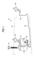
- a headlamp cleaner 10 includes a tank 14 for holding a washer fluid, a motor pump 30 which pumps the washer fluid inside the tank 14 and pressure-feeds the washer fluid into a conduit 22, and nozzles 18, 20 disposed at distal ends of the conduit 22 to eject the washer fluid toward right and left headlamps (not shown) of a vehicle.
- the headlamp cleaner 10 is arranged on a rear side of a bumper 24 of a vehicle body.
- the headlamp cleaner 10 further includes a filling port 12 from which the washer fluid is supplied into the tank 14.
- the washer fluid inside the tank 14 is pumped by the motor pump 30 and is pressure-fed to the respective nozzles 18, 20 so that surfaces of the headlamps are cleaned with the washer fluids ejected from the respective nozzles 18, 20, whereby the functions of the headlamps can be restored to ensure visibility even when a dirt is stuck onto the headlamps.
- a motor pump 30 has a cylindrical casing 32 inside which a pump chamber 50, a motor housing chamber 60 and a board housing chamber 80 are integrally formed.
- the pump chamber 50 is formed below the motor housing chamber 60 in which a motor 62 is accommodated, and the motor housing chamber 60 is formed below the board housing chamber 80 in which a control circuit board 82 is accommodated.
- the casing includes a connector portion 70 to which a power-side connector 90 is coupled.
- the pump chamber 50 communicates with an inner side of the tank 14 via a suction port 52 below the pump chamber 50 and with the conduit 22 via a discharge port 54 extending sideways from the pump chamber 50.
- an impeller 56 which is coupled to a drive shaft 65 of the motor 62 disposed inside the motor housing chamber 60.
- a bushing 58 is arranged between the pump chamber 50 and the motor housing chamber 60 to seal a space therebetween.
- the motor pump 30 is held in a recess portion 15 formed on a side wall of the tank 14, and is fixed such that the suction port 52 extends into the tank 14. Accordingly, the washer fluid is introduced from the suction port 52 into the pump chamber 50 as the impeller 56 is rotated by the motor 62, and is pressure-fed from the discharge port 54 into the conduit 22.
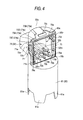
- the connector portion 70 is disposed between the motor housing chamber 60 and the board housing chamber 80. That is, the connector portion 70 outwardly extends, in a cylindrical shape, from a portion of the casing 32 above the motor housing chamber 60 in a direction intersecting with (in the first exemplary embodiment, substantially orthogonal to) a longitudinal direction of the casing 32, and a plurality of terminal pieces 71, 72, 73 are arranged on an inner side of the connector portion 70.
- the connector portion 70 extends, more specifically, sideways from a lower half of the portion of the casing 32 above the motor housing chamber 60. In other words, a base end portion of the connector portion 70 is a part of a semicylindrical portion 32a of the casing 32.
- the board housing chamber 80 is formed on a rear side of the base end portion of the connector portion 70 (the semicylindrical portion 32a) inside the casing 32, and the control circuit board 82 having a control circuit 82a for driving the motor 62 is accommodated in the board housing chamber 80.
- the board housing chamber 80 occupies about a half of horizontal sectional area of an upper portion of the casing 32, and is formed to have a vertically long space allowing the control circuit board 82 to be arranged in a vertical direction (i.e., the vertical arrangement).
- the terminal pieces 71, 72, 73 inside the connector portion 70 are arranged between the control circuit board 82, which is accommodated inside the board housing chamber 80, and the motor 62, which is accommodated inside the motor housing chamber 60.
- the power feeding terminal piece 71, the grounding terminal piece 72 and the control signal terminal pieces 73 are integrally fixed to the casing 32 inside of the connector portion 70, and respective tip ends 71a, 72a, 73a thereof are arranged in two stages (in upper and lower rows).
- the terminal pieces 71, 72, 73 are busbars which are stripe-shaped pieces made of conductive material.
- the power feeding terminal piece 71 horizontally extends along a curved wall of the casing 32, and is downwardly bent such that the other end 71b of the terminal piece 71 is exposed at a communication hole 78a, via which the motor housing chamber 60 and a inner space of the connector portion (and the board housing chamber 80) are communicated with each other, to contact a positive electrode terminal 63 of the motor 62.
- the grounding terminal piece 72 and the control signal terminal pieces 73 are straight busbars horizontally extending through a terminal portion 32b, which is a portion of the casing 32, from the inner side of the connector portion 70 into the board housing chamber 80. End portions 72b, 73b of the terminal pieces 72, 73 protruding into the board housing chamber 80 are inserted into respective terminal engaging holes 83 of the control circuit board 82, and are soldered to a conducting path (not shown) formed around the terminal engaging holes 83 for control signals.
- the control signal terminal pieces 73 includes a headlamp signal terminal piece 73A, a front windshield washer signal terminal piece 73B, a cleaner switch signal terminal piece 73 C and an ignition signal terminal piece 73D.
- Another grounding terminal piece 75 is also a busbar, and electrically couples a negative electrode terminal 64 of the motor 62 and a grounding conducting path (not shown) on the control circuit board 82.
- a lower end portion 75a of this grounding terminal piece 75 is exposed at a communication hole 78b communicating the motor housing chamber 60 and the inner space of the connector portion 70 (and the board housing chamber 80), and contacts the negative electrode terminal 64.
- the other end portion 75b of the grounding terminal 75 protruding into the board housing chamber 80 is inserted into a corresponding terminal engaging hole 83 of the control circuit board 82, and is soldered to the grounding conducting path around the terminal engaging hole 83.
- the power feeding terminal piece 71 and the grounding terminal piece 75 are coupled to the electrode terminals 63, 64 of the motor 62 through the communication holes 78a, 78b, while these communication holes 78a, 78b communicates the motor housing chamber 60 and the board housing chamber 80 with each other. Therefore, the communication holes 78a, 78b facilitate a generation of air convections between the motor housing chamber 60 and the board housing chamber 80, thereby preventing heat from being confined within the motor housing chamber 60. More specifically, an air hole (not shown) is formed in a lower portion of a side wall of a motor housing 61.
- the protruding end portions 72b, 73b, 75b of the grounding terminal pieces 72, 75 and the control signal terminal pieces 73 are positioned in alignment with the corresponding terminal engaging holes 83 of the control circuit board 82, and protruding lengths from respective terminal reference planes 32b1 are set to be substantially equal. Therefore, an arrangement and positioning of the control circuit board 82 can be implemented simply by inserting the protruding end portions 72b, 73b, 75b into the corresponding terminal engaging holes 83 and pushing the control circuit board 82 against the terminal reference planes 32b1.
- the protruding end portions 72b, 73b, 75b are soldered to the corresponding conducting paths around the terminal engaging holes 83, whereby the busbars 72, 73, 75 and the control circuit 82a on the control circuit board 82 can be reliably connected.
- the motor pump 30 is held and fixed in the recess portion 15 which is formed be inwardly denting the side wall of the washer fluid tank 14, and the connector portion 70 outwardly extends from the casing 32 so as to be exposed to an outer side area of the side wall of the tank 14 (see Fig. 1 ). Therefore, it is easy to attach or to detach the power-side connector 90 with respect to the connector portion 70.
- the power feeding terminal piece 71 inside the connector portion 70 is directly coupled to the positive electrode terminal 63 of the motor 62, i.e., not coupled to the control circuit board 82.
- the control circuit board 82 can be downsized, resulting in downsizing of the board housing chamber 80 and the motor pump 30.
- the recess portion 15 of the washer fluid tank 14 can also be made small to increase the effective capacity of the washer fluid tank 14 (i.e., to increase an amount of the washer fluid to be held in the washer fluid tank 14).
- motor drive control functions can be enhanced by providing an additional control circuit to a space that can be utilized in place of forming the terminal engaging hole for the terminal 71 b.
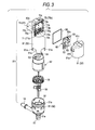
- the casing 32 includes a pump housing 51 defining the pump chamber 50, the motor housing 61 defining the motor housing chamber 60 and which is formed in a one-piece structure with the connecter portion 70, and a board cover 81 defining the board housing chamber 80.
- Tongue-shaped elastic hooks 61a are formed to extend from positions that are equally spaced along a circumference of a lower end of the motor housing 61, and grooves 51 a are formed on an outer circumference of the pump housing 51 so as to correspond to each of the elastic hooks 61a.
- the motor housing 61 and the pump housing 51 are integrally attached by engaging the elastic hooks 61a and the grooves 51 a with each other.
- the board cover 81 is semicylindrical, and has a C-shaped longitudinal section (see Fig. 5 ).
- the board cover 81 has a rectangular front opening peripheral edge portion 81a (see Fig. 3 ) which matches a rectangular rear opening peripheral edge portion 70a (see Figs. 3 and 4 ) of the semicylindrical portion 32a.
- the rear opening peripheral edge portion 70a serves as a base end portion of the connector portion 70.
- a pair of elastic hooks 8 1b on a side wall and another elastic hook 81 c on a ceiling of the board cover 81 are engaged with hook engaging portions 70b, 70c of the connector portion 70, whereby the board cover 81 is integrally attached to the connector portion, i.e., to the motor housing 61.
- a seal packing 86 is sandwiched between the rear opening peripheral edge portion 70a of the connector portion 70 and the front opening peripheral edge portion 81a of the board cover 81, thereby keeping the board housing chamber 80 water-proof.
- the motor 62 When assembling the motor pump 30, firstly, the motor 62 is housed inside the motor housing 61 such that the electrode terminals 63, 64 of the motor 62 are brought into contact with the end portion 71b of the power feeding terminal piece 71 and the end portion 75a of the grounding terminal piece 75, which are exposed to the communication holes 78a, 78b between the board housing chamber 80 and the motor housing chamber 60 respectively. It can be confirmed from a side of the board housing chamber 80 whether or not the terminal 63 and the terminal 71b, and the terminal 64 and the terminal piece 75a are in pressure-contact respectively.
- control circuit board 82 is arranged such that the terminal engaging holes 83 engage with the respective protruding end portions 72b, 73b, 75b protruding toward the board housing chamber 80 from the motor housing 61, and after coupling the respective terminals 72b, 73b, 75b to the motor drive control circuit 82a of the control circuit board 82, the board cover 81 is integrally assembled so as to surround the board housing chamber 80.
- the impeller 56 is fixed to the drive shaft 65 of the motor 62 with the bushing 58 interposed therebetween, and the pump housing 51 is fitted into the lower end portion of the motor housing 61.
- the motor drive control circuit 82a of the control circuit board 82 includes an interface section, a timer section and a motor driving section, and is configured such that, when a cleaner switch (not shown) in an interior of the vehicle is turned on, the motor 62 is instantly driven for a certain period of time (e.g., T seconds) so that the washer fluid is ejected from the nozzles 18, 20 for a certain period of time (e.g., T seconds).
- this drive control circuit 82a is configured to have a relay circuit of the timer section and the motor driving section so as to have a control logic to inhibit a continuous driving of the motor 62. More specifically, as shown in Fig. 7 , this control logic is such that an input from the cleaner switch (i.e., a signal for driving the motor 62) is not accepted until a certain period of time (e.g., T/2 seconds) elapses after a stoppage of the latest drive of the motor 62 was stopped.
- a certain period of time e.g., T/2 seconds
- an inactive time for the motor 62 after a drive of the motor 62 can always be ensured for a certain period of time (e.g., T/2 seconds), whereby it is possible to reliably suppress a heat generation caused by the continuous drive which might otherwise causes trouble with the motor 62.
- a motor pump (not shown) for a windshield washer is also provided on the washer fluid tank 14, and is driven by turning on a windshield washer switch provided in the interior of the vehicle.
- the washer fluid inside the tank 14 is pressure-fed to a front windshield washing nozzle (not shown) through a conduit (not shown), and is ejected from the front windshield washing nozzle toward a front windshield of the vehicle.
- the motor pump 30 is also driven under a certain condition to also wash the headlamps.
- the motor drive control circuit 82a is configured such that, when the windshield washer switch is turned on while the headlamps are being turned on, the motor 62 is driven for a certain period of time irrespective of turning on and off of the cleaner switch so that the washer fluid is ejected from the nozzles 18, 20.
- the headlamp cleaner 10 is actuated in response to the operation of the windshield washer.
- the motor drive control circuit 82a having electronic parts mounted thereon is provided only on one surface of the control circuit board 82.
- the semicylindrical portion 32a which is the base end portion of the connector portion 70
- the power feeding terminal piece 71 arranged inside the connector portion 70 is directly coupled to the positive electrode terminal 63 of the motor 62, the negative electrode terminal 64 of the motor 62 is coupled to the motor drive control circuit 82a via the grounding terminal piece 75, the motor drive control circuit 82a is coupled to the grounding terminal piece 72 arranged inside the connector portion 70.
- the motor 62 is directly powered from inside the connector portion 70.
- the motor 62 may be powered via the motor drive control circuit 82a.
- Fig. 6B there may be a configuration in which the terminal piece 71 arranged inside the connector portion 70 is directly coupled to the negative electrode terminal 64 of the motor 62 to function as a grounding terminal, the terminal piece 72 arranged inside the connector portion 70 is coupled to a motor drive control circuit 82b to function as a power feeding terminal, and the terminal piece 75 is coupled to the positive electrode terminal 63 of the motor 62 to function as another power feeding terminal.
- the configuration of the motor drive control circuit 82b is partially different from the motor drive control circuit 82a shown in Fig. 6A so as to correspond to a wiring configuration shown in Fig. 6B .
- Fig. 8 is an exploded perspective view of a motor pump 30A according to a second exemplary embodiment.
- a motor housing 61A and a connector portion 70A of the motor pump 30A are provided as separate members.
- the motor housing 61 A and the connector portion 70A are attached together by fitting, in an longitudinal direction of the motor pump 30A, a projecting rib (not shown) formed on an inner circumference of a cylindrical lower end portion 70d of the connector portion 70A onto a groove 61b formed on an outer circumference of a ceiling portion of the motor housing 61A, with a seal ring 61 c interposed therebetween.
- a ceiling of the motor housing 61A is formed with holes 78a1, 78b1, through which the pair of electrode terminals 63, 64 of the motor 62 are protruded toward the motor housing chamber 60 respectively.
- a lower face of the connector portion 70A is also formed with holes 78a2, 78b2 corresponding to the holes 78a1, 78b1 of the motor housing 61A, and the protruding end portions 71b, 75a of the power feeding terminal piece 71 and the grounding terminal piece 75 are respectively exposed from the holes 78a1, 78b1.
- These holes 78a1, 78a2 and 78b1, 78b2 correspond to the communication holes 78a, 78b of the first exemplary embodiment, which are formed on the connector portion 70 of the motor pump 30.
- Figs. 9A to 10 show a motor pump 30B according to a third exemplary embodiment.
- the motor pump 30B has a motor housing 61B and a connector portion 70B which are provided as separate members.
- the coupling structure of the motor housing 61B and the connector portion 70B is different from that of the motor housing 61A and the connector portion 70A of the second exemplary embodiment.
- a rectangular-cylindrical neck portion 61B 1 is formed to extend upward from a ceiling of the motor housing 61B, and another rectangular-cylindrical neck portion 70B1, which is engageable with an outer side portion of the neck portion 61B 1 of the motor housing 61, is formed to extend downward from a lower end portion of the connector portion 70B.
- the ceiling of the motor housing 61B is formed with holes, which are similar to the holes 78a1, 78b1 formed of the motor housing 61A of the second exemplary embodiment, on an inner side of the neck portion 61B1.
- the pair of electrode terminals 63, 64 of the motor 62 arranged inside the motor housing chamber 60 protrude from these holes into the neck portion 61B1.
- the power feeding terminal piece 71 and the grounding terminal piece 75 are extended downward while being supported by a portion of the neck portion 70B1. As shown in Fig. 9C , extending end portions 71c and 75c of the respective terminal pieces 71, 75 are formed with holding portions, which are female terminals.
- An elastic hook 70B2 is formed to extend from the neck portion 70B 1 of the connector portion 70B, and a locking portion 61B2 for an engagement with the elastic hook 70B2 of the connector portion 70B is formed on the neck portion 61B1 of the motor housing 61B.
- the elastic hook 70B2 engages with the hook portion 61B2 such that it is prevented from being erroneously pulled out, and the pair of electrode terminals 63, 64 of the motor 62 are fitted in the female terminals (or the holding portions) 71c, 75c of the terminals pieces 71, 75.
- a seal packing 70B3 is interposed between the neck portions 61B 1, 70B 1.
- Figs. 11 and 12 show a motor pump 30C according to a fourth exemplary embodiment.
- the connectors 70, 70A, 70B are extended substantially perpendicular to the longitudinal direction the casing 32, i.e., substantially perpendicular to a direction in which the drive shaft 65 of the motor 62 extends.
- a connector portion 70C is extended obliquely upward from the ceiling of the casing 32.
- the board housing chamber 80 is formed in the upper portion of the inside of the casing 32 in the first to third exemplary embodiments, in this fourth exemplary embodiment, the board housing chamber 80 is formed in an outwardly protruded portion 33 having a rectangular shape, which is disposed right below the connector portion 70C along the outer side portion of the casing 32 (the motor housing 61).
- the outwardly protruded portion 33 includes a bottomed board cover 81A having a rectangular shape.
- the bottomed board cover 81A is attached to the casing 32 (the motor housing 61) by an engagement between a pair of right and left elastic hooks (not shown) formed on right and left side walls of the board cover 81A and a pair of locking portions (not shown) formed at the outer circumference of the casing 32.
- a seal packing 86 is interposed between the rear opening peripheral edge portion of the bottomed board cover 81A and a surface of the casing 32 to which the board cover 81A is attached.
- the ceiling of the motor housing 61 is formed with the communication holes 78a, 78b (the communication hole 78a not shown in Fig. 11 ) for communicating the inside of the connector portion 70C with the motor housing chamber 60.
- the pair of electrode terminals 63, 64 (the electrode terminal 63 is not shown in Fig. 11 ) of the motor 62 arranged inside the motor housing chamber 60 are protruded from the communication holes 78a, 78b into the space inside the connector portion 70C.
- the power feeding terminal piece 71 Inside the connector portion 70C, there are arranged the power feeding terminal piece 71, the grounding terminal piece 72 and the control signal terminal piece 73 (73A to 73D), the respective end portions 71a, 72a, 73a of which are extended in parallel with a direction in which the connector portion 70 extends and are systematically arranged in upper and lower stages.
- the grounding terminal piece 72 and the control signal terminal pieces 73 are busbars bent in a V-shape, and the other end portions 72b, 73b of the terminal pieces 72, 73 (73A to 73D) are extended inside the casing 32 and are protruded into the board housing chamber 80 inside the outwardly protruded portion 33.
- the power feeding terminal piece 71 is a busbar extending from the inside of the connector portion 70C so as to be exposed to the motor housing chamber 60, and is formed such that an end portion there of is upwardly bent from the horizontally extending portion arranged along the casing.
- the end portion of the terminal piece 71 is set upward at a position corresponding to the communication hole 78a inside the connector portion 70C, and this raised end portion 71c is formed with a holding portion being a female terminal.
- the grounding terminal piece 75 is a busbar coupling the negative electrode terminal 64 of the motor 62 and the grounding conducting path (not shown) of the control circuit board 82.
- the one end portion 75b is so positioned together with the protruding end portions 72b, 73b of the other terminal pieces 72, 73 as to protrude into the board housing chamber 80.
- the other end portion is set upward at a position corresponding to the communication hole 78b inside the connector portion 70C, and this raised tip end portion 75c is formed with a holding portion being another female terminal.
- the electrode terminals 63, 64 of the motor 62 which protrude from the communication holes 78a, 78b into the connector portion 70C, are automatically fitted into the female terminals 71c, 75c above the communication holes 78a, 78b, respectively.
- the end portions 72b, 73b, 75b of the terminal pieces 72, 73 (73A to 73D), 75 are positioned and protruded to an outer side of the motor housing 61 (into the board housing chamber 80) right below the connector portion 70C. Therefore, the control circuit board 82 is vertically arranged such that the terminal engaging holes 83 engage with the protruding end portions 72b, 73b, 75b of the terminal pieces 72, 73, 75, and the board cover 81 A is then attached to cover the control circuit board 82), whereby the motor pump 30C is assembled.
- the remaining configurations of the fourth exemplary embodiment are similar to those of the motor pumps 30, 30A, 30B of the first to third exemplary embodiments. Thus, repetitive explanations thereof are omitted and like parts are designated by the same reference numerals.
- the motor pump 30C of the fourth exemplary embodiment may have one or more of the following advantages.
- the worker When attaching or detaching the power-side connector 90 (vehicle-side connector) with respect to the connector portion of the motor pump, the worker bends his or her upper body into the engine room, and pushes the power-side connector 90 obliquely downward from above the connector portion or pulls the power-side connector 90 obliquely upward. Therefore, as compared with the first to third exemplary embodiments in which the power-side connector 90 needs to be attached to the connector portion of the motor pump in a lateral direction from a side of the connector portion, the worker can easily attach or detach the power-side connector 90 without taking an awkward posture.
- the outwardly protruded portion 33 is disposed on the side of the casing 32 right below the connector portion 70 and is used as the board housing chamber 80, it is possible to considerably shorten the height (the total length) of the motor pump as compared with the configuration in which the board housing chamber 80 is formed to vertically extend above the motor housing chamber 60.
- the motor pump 30C of the fourth exemplary embodiment while the control circuit board 82 is arranged vertically, the motor pump can still be downsized in the vertical direction. As a result, the vertical length of the recess portion 15 of the washer fluid tank 14 can be reduced so that the effective capacity of the washer fluid tank 14 can be increased.
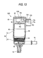
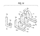
- Figs. 13 and 14 show a motor pump 30D according to a fifth exemplary embodiment.
- the motor pump 30D is configured such that the board housing chamber 80 is longer in the lateral direction than in the vertical direction, and the control circuit board 82 is laterally arranged.
- the board housing chamber 80 is formed above the motor housing chamber 60 of the casing 32 while utilizing the entire lateral sectional area of inside the casing 32 (the motor housing 61).
- a board cover 81B is engageable with an upper end portion of the casing 32 (the motor housing 61), and is integrally attached to the casing 32 (the motor housing 61) with locking means (not shown) disposed between board cover 81B and the casing 32 (the motor housing 61).
- a connector portion 70D and the motor housing 61 are formed in a one-piece structure, and the power feeding terminal piece 71, the grounding terminal piece 72 and the control signal terminal piece 73 (73A to 73D) are arranged inside the connector portion 70D.
- the respective end portions 71a, 72a, 73a are extended along a direction in which the connector portion 70D extends, and are arranged in upper and lower stages.
- the grounding terminal piece 72 and the control signal terminal pieces 73 are busbars bent in an L shape, and the other end portions 72b, 73b of the respective terminal pieces 72, 73 (73A to 73D) are extended upward inside the board housing chamber 80.
- the power feeding terminal piece 71 which is extended from the inside of the connector portion 70D so as to be exposed to the motor housing chamber 60, is a busbar which is extended horizontally along the casing 32 and downwardly bent.
- the other end portion 71c of the terminal piece 71 which is positioned to correspond to the communication hole 78a formed on the bottom surface of the board housing chamber 80, is formed with a holding portion being a female terminal.
- the grounding terminal piece 75 which is a L-shaped busbar coupling the negative electrode terminal 64 of the motor 62 and the grounding conducting path (not shown) of the control circuit board 82, is so positioned together with the protruding end portions 72b, 73b of the other terminals 72, 73 as to protrude upward.
- the other end portion 75c which is positioned to correspond to the communication hole 78b formed on the bottom surface of the board housing chamber 80, is formed with a holding portion being another female terminal.
- the end portions 72b, 73b, 75b which are so positioned with respect to a terminal reference plane (not shown) as to protrude upward, are engaged with the terminal engaging holes 83 of the control circuit board 82, and the control circuit board 82 laterally arranged.
- the electrode terminals 63, 64 of the motor 62 which protrude into the board housing chamber 80 through the communication holes 78a, 78b of the bottom surface of the board housing chamber 80, are fitted into the female terminals 71c, 75c, respectively, which are disposed above the communication holes 78a, 78b.
- the remaining configurations of the fifth exemplary embodiment are similar to those of the motor pump 30, 30A, 30B, 30C of the first to fourth exemplary embodiments. Thus, repetitive explanations thereof are omitted and like parts are designated by the same reference numerals.
- the vertical dimension of the motor pump 30D can be made small.
- the recess portion 15 of the washer fluid tank 14 can be made smaller so that the effective capacity of the washer fluid tank 14 is increased.
Landscapes
- Engineering & Computer Science (AREA)
- Mechanical Engineering (AREA)
- Power Engineering (AREA)
- General Engineering & Computer Science (AREA)
- Water Supply & Treatment (AREA)
- Microelectronics & Electronic Packaging (AREA)
- Structures Of Non-Positive Displacement Pumps (AREA)
- Motor Or Generator Frames (AREA)
Applications Claiming Priority (1)
| Application Number | Priority Date | Filing Date | Title |
|---|---|---|---|
| JP2007176944A JP5209907B2 (ja) | 2007-07-05 | 2007-07-05 | ヘッドランプクリーナ装置用モータポンプ |
Publications (2)
| Publication Number | Publication Date |
|---|---|
| EP2011704A2 true EP2011704A2 (de) | 2009-01-07 |
| EP2011704A3 EP2011704A3 (de) | 2010-03-10 |
Family
ID=39730851
Family Applications (1)
| Application Number | Title | Priority Date | Filing Date |
|---|---|---|---|
| EP08159757A Withdrawn EP2011704A3 (de) | 2007-07-05 | 2008-07-04 | Motorpumpe für Scheinwerferreiniger |
Country Status (5)
| Country | Link |
|---|---|
| US (1) | US8262374B2 (de) |
| EP (1) | EP2011704A3 (de) |
| JP (1) | JP5209907B2 (de) |
| KR (1) | KR100983598B1 (de) |
| CN (1) | CN101337537B (de) |
Cited By (3)
| Publication number | Priority date | Publication date | Assignee | Title |
|---|---|---|---|---|
| FR2992794A1 (fr) * | 2012-06-29 | 2014-01-03 | Leroy Somer Moteurs | Machine electrique tournante equipee d'une boite a bornes. |
| CN103909908A (zh) * | 2013-01-09 | 2014-07-09 | 株式会社小糸制作所 | 灯清洁装置用喷嘴装置及其组装方法 |
| EP3079237A1 (de) * | 2015-04-08 | 2016-10-12 | Siemens Aktiengesellschaft | Gehäuse für einen messwertgeber oder eine elektrische maschine |
Families Citing this family (15)
| Publication number | Priority date | Publication date | Assignee | Title |
|---|---|---|---|---|
| JP5205288B2 (ja) * | 2009-01-07 | 2013-06-05 | 株式会社小糸製作所 | ヘッドランプクリーナ装置用モータポンプ |
| JP5393217B2 (ja) * | 2009-03-25 | 2014-01-22 | 株式会社小糸製作所 | ヘッドランプクリーナーのモーターポンプ |
| KR101388370B1 (ko) * | 2010-02-02 | 2014-04-23 | 주식회사 만도 | 모터 및 전자제어유닛을 통합하기 위한 파워 팩 장치 |
| CN102562605A (zh) * | 2010-12-06 | 2012-07-11 | 株式会社博世电装 | 车辆的冲洗泵 |
| JP2012180828A (ja) * | 2011-02-07 | 2012-09-20 | Aisan Industry Co Ltd | 電動ポンプ |
| CA2865394C (en) * | 2012-02-27 | 2019-04-02 | Magna Powertrain Of America Inc. | Electric motor -driven pump |
| JP5464224B2 (ja) * | 2012-03-14 | 2014-04-09 | 株式会社安川電機 | モータ駆動装置および車両 |
| JP5476407B2 (ja) * | 2012-03-14 | 2014-04-23 | 株式会社安川電機 | モータ駆動装置および車両 |
| EP2750268B1 (de) * | 2012-12-27 | 2015-10-14 | Grundfos Holding A/S | Pumpenaggregat |
| KR101929756B1 (ko) * | 2013-09-03 | 2018-12-17 | 주식회사 세종에이티티 | 전자 제어 유닛의 핀부재 |
| US11070106B2 (en) * | 2017-07-31 | 2021-07-20 | Nidec Tosok Corporation | Electric oil pump |
| JP7134650B2 (ja) | 2018-03-08 | 2022-09-12 | ミネベアミツミ株式会社 | 回転装置、回転装置の取付構造、及び回転装置と外部コネクタとの接続構造 |
| JP6975209B2 (ja) * | 2019-07-02 | 2021-12-01 | 本田技研工業株式会社 | 駆動ユニット |
| CN110341653B (zh) * | 2019-08-08 | 2024-12-10 | 温岭市华康汽车零部件有限公司 | 一种汽车雨刷喷水电机 |
| DE102025122058A1 (de) * | 2024-08-02 | 2026-02-05 | Hanon Systems Efp Deutschland Gmbh | Pumpengehäuse und pumpe |
Citations (4)
| Publication number | Priority date | Publication date | Assignee | Title |
|---|---|---|---|---|
| DE3922230A1 (de) | 1989-07-06 | 1991-01-17 | Duerrwaechter E Dr Doduco | Schaltungsanordnung fuer eine scheibenwisch- und -waschanlage in kraftfahrzeugen |
| JPH04121256A (ja) | 1990-09-11 | 1992-04-22 | Koito Mfg Co Ltd | ヘツドランプクリーナ制御回路 |
| DE4120665A1 (de) | 1991-06-22 | 1992-12-24 | Teves Gmbh Alfred | Elektromotorisch angetriebene hydraulikpumpe |
| DE4411960A1 (de) | 1994-04-07 | 1995-10-12 | Pierburg Gmbh | Elektronisch kommutierter Elektromotor |
Family Cites Families (19)
| Publication number | Priority date | Publication date | Assignee | Title |
|---|---|---|---|---|
| JPS497665Y1 (de) * | 1970-06-24 | 1974-02-22 | ||
| JPS58107554A (ja) | 1981-12-22 | 1983-06-27 | Fuji Xerox Co Ltd | 画像形成方法 |
| JPS6015998U (ja) * | 1983-07-11 | 1985-02-02 | カルソニックカンセイ株式会社 | ポンプの取付装置 |
| JPS6375302A (ja) | 1986-09-17 | 1988-04-05 | Toshiba Corp | 回転機械の軸受潤滑油供給装置 |
| DE19903817A1 (de) * | 1999-02-02 | 2000-08-10 | Bosch Gmbh Robert | Kühlwasserpumpe |
| DE19956380C1 (de) * | 1999-11-24 | 2001-01-04 | Bosch Gmbh Robert | Flüssigkeitspumpe mit einem Motorgehäuse und Verfahren zur Herstellung eines Motorgehäuses |
| JP2002070743A (ja) * | 2000-08-29 | 2002-03-08 | Sanden Corp | 冷媒圧縮用電動式圧縮機 |
| JP4121256B2 (ja) | 2001-06-12 | 2008-07-23 | 富士フイルム株式会社 | 網点閾値データ作成方法 |
| US6675989B1 (en) * | 2001-06-28 | 2004-01-13 | Valeo Electrical Systems, Inc. | Windshield washer pump with integrated fluid level sensor |
| ES1049538Y (es) | 2001-07-03 | 2002-05-16 | Fico Transpar Sa | Electrobomba para lavaparabrisas de vehiculos automoviles. |
| EP1464106A1 (de) * | 2002-01-11 | 2004-10-06 | ebm-papst St. Georgen GmbH & Co. KG | KLEIN- ODER KLEINSTLüFTER |
| JP3786356B2 (ja) * | 2002-04-26 | 2006-06-14 | 株式会社デンソー | 車両用インバータ一体型電動コンプレッサ |
| JP2004162541A (ja) * | 2002-11-11 | 2004-06-10 | Calsonic Kansei Corp | 電動ブラシレスウォータポンプ |
| DE10302130A1 (de) * | 2003-01-21 | 2004-08-05 | Minebea Co., Ltd. | Motorgehäuse für einen Elektromotor |
| JP2004350458A (ja) * | 2003-05-23 | 2004-12-09 | Asmo Co Ltd | 車両用モータポンプ装置及び車両用ウォッシャ装置 |
| US7365458B2 (en) * | 2005-03-31 | 2008-04-29 | Nidec Shibaura Corporation | Brushless DC motor with molded resin housing |
| JP2006291776A (ja) | 2005-04-07 | 2006-10-26 | Asmo Co Ltd | ポンプ装置および車両用ウォッシャポンプ装置 |
| WO2008019818A1 (de) | 2006-08-14 | 2008-02-21 | Grundfos Management A/S | Statoranordnung für ein pumpenaggregat |
| JP4909185B2 (ja) | 2007-06-11 | 2012-04-04 | アスモ株式会社 | ポンプ装置、ポンプ装置の組み付け方法、車両用ウォッシャ装置 |
-
2007
- 2007-07-05 JP JP2007176944A patent/JP5209907B2/ja not_active Expired - Fee Related
-
2008
- 2008-07-03 US US12/167,612 patent/US8262374B2/en not_active Expired - Fee Related
- 2008-07-04 EP EP08159757A patent/EP2011704A3/de not_active Withdrawn
- 2008-07-04 KR KR1020080064898A patent/KR100983598B1/ko not_active Expired - Fee Related
- 2008-07-07 CN CN2008101276634A patent/CN101337537B/zh not_active Expired - Fee Related
Patent Citations (4)
| Publication number | Priority date | Publication date | Assignee | Title |
|---|---|---|---|---|
| DE3922230A1 (de) | 1989-07-06 | 1991-01-17 | Duerrwaechter E Dr Doduco | Schaltungsanordnung fuer eine scheibenwisch- und -waschanlage in kraftfahrzeugen |
| JPH04121256A (ja) | 1990-09-11 | 1992-04-22 | Koito Mfg Co Ltd | ヘツドランプクリーナ制御回路 |
| DE4120665A1 (de) | 1991-06-22 | 1992-12-24 | Teves Gmbh Alfred | Elektromotorisch angetriebene hydraulikpumpe |
| DE4411960A1 (de) | 1994-04-07 | 1995-10-12 | Pierburg Gmbh | Elektronisch kommutierter Elektromotor |
Cited By (6)
| Publication number | Priority date | Publication date | Assignee | Title |
|---|---|---|---|---|
| FR2992794A1 (fr) * | 2012-06-29 | 2014-01-03 | Leroy Somer Moteurs | Machine electrique tournante equipee d'une boite a bornes. |
| WO2014002071A1 (fr) * | 2012-06-29 | 2014-01-03 | Moteurs Leroy-Somer | Machine electrique tournante equipee d'une boite a bornes |
| US10097061B2 (en) | 2012-06-29 | 2018-10-09 | Moteurs Leroy-Somer | Rotary electric machine equipped with a terminal box |
| CN103909908A (zh) * | 2013-01-09 | 2014-07-09 | 株式会社小糸制作所 | 灯清洁装置用喷嘴装置及其组装方法 |
| CN103909908B (zh) * | 2013-01-09 | 2016-05-11 | 株式会社小糸制作所 | 车辆的前灯清洁装置用喷嘴装置及其组装方法 |
| EP3079237A1 (de) * | 2015-04-08 | 2016-10-12 | Siemens Aktiengesellschaft | Gehäuse für einen messwertgeber oder eine elektrische maschine |
Also Published As
| Publication number | Publication date |
|---|---|
| JP5209907B2 (ja) | 2013-06-12 |
| KR100983598B1 (ko) | 2010-09-24 |
| US8262374B2 (en) | 2012-09-11 |
| CN101337537A (zh) | 2009-01-07 |
| EP2011704A3 (de) | 2010-03-10 |
| JP2009013878A (ja) | 2009-01-22 |
| CN101337537B (zh) | 2012-11-14 |
| US20090010787A1 (en) | 2009-01-08 |
| KR20090004752A (ko) | 2009-01-12 |
Similar Documents
| Publication | Publication Date | Title |
|---|---|---|
| US8262374B2 (en) | Motor pump for headlamp cleaner | |
| JP5205288B2 (ja) | ヘッドランプクリーナ装置用モータポンプ | |
| JP3846604B2 (ja) | 燃料供給装置 | |
| CN109689446A (zh) | 清洁器、带清洁器的传感器以及具有该清洁器或该带清洁器的传感器的车辆 | |
| CN105075031B (zh) | 车辆侧连接器 | |
| JP4359806B2 (ja) | 燃料供給装置 | |
| CN101846084A (zh) | 电动泵 | |
| CN104554180B (zh) | 整体的流体储存器结构和车轮衬件防溅板 | |
| US3316847A (en) | Windshield washer system | |
| JP6561916B2 (ja) | コネクタ | |
| JP3938432B2 (ja) | 燃料タンクの蓋体構造 | |
| KR101466038B1 (ko) | 연료펌프모듈 | |
| US20070144608A1 (en) | Fuel flange with discharge structure to discharge conductive hoses | |
| JP2006291776A (ja) | ポンプ装置および車両用ウォッシャポンプ装置 | |
| JP5316358B2 (ja) | 燃料供給装置 | |
| JP7616034B2 (ja) | 電動圧縮機 | |
| CN105026745B (zh) | 燃料供给装置 | |
| US20080251149A1 (en) | Fuel pump housing | |
| JP2501606Y2 (ja) | ホ―スの接続装置 | |
| JP2007253867A (ja) | ウォッシャ液供給装置 | |
| JP7321041B2 (ja) | 燃料ポンプモジュール | |
| CN100379614C (zh) | 玻璃清洗装置与汽车零件的组合 | |
| JP2007253846A (ja) | ウォッシャ液供給装置 | |
| KR20100129458A (ko) | 워셔액 펌프장치 | |
| JP3854198B2 (ja) | 洗浄装置及び洗浄装置の回路ボックス固定方法 |
Legal Events
| Date | Code | Title | Description |
|---|---|---|---|
| PUAI | Public reference made under article 153(3) epc to a published international application that has entered the european phase |
Free format text: ORIGINAL CODE: 0009012 |
|
| 17P | Request for examination filed |
Effective date: 20080724 |
|
| AK | Designated contracting states |
Kind code of ref document: A2 Designated state(s): AT BE BG CH CY CZ DE DK EE ES FI FR GB GR HR HU IE IS IT LI LT LU LV MC MT NL NO PL PT RO SE SI SK TR |
|
| AX | Request for extension of the european patent |
Extension state: AL BA MK RS |
|
| PUAL | Search report despatched |
Free format text: ORIGINAL CODE: 0009013 |
|
| AK | Designated contracting states |
Kind code of ref document: A3 Designated state(s): AT BE BG CH CY CZ DE DK EE ES FI FR GB GR HR HU IE IS IT LI LT LU LV MC MT NL NO PL PT RO SE SI SK TR |
|
| AX | Request for extension of the european patent |
Extension state: AL BA MK RS |
|
| RIC1 | Information provided on ipc code assigned before grant |
Ipc: H02K 5/22 20060101ALN20100203BHEP Ipc: H02K 11/00 20060101ALI20100203BHEP Ipc: B60S 1/48 20060101AFI20081001BHEP |
|
| AKX | Designation fees paid |
Designated state(s): DE FR GB |
|
| STAA | Information on the status of an ep patent application or granted ep patent |
Free format text: STATUS: THE APPLICATION HAS BEEN WITHDRAWN |
|
| 18W | Application withdrawn |
Effective date: 20150701 |