EP2011719A2 - Bodenstruktur eines Kraftfahrzeugs - Google Patents
Bodenstruktur eines Kraftfahrzeugs Download PDFInfo
- Publication number
- EP2011719A2 EP2011719A2 EP08011591A EP08011591A EP2011719A2 EP 2011719 A2 EP2011719 A2 EP 2011719A2 EP 08011591 A EP08011591 A EP 08011591A EP 08011591 A EP08011591 A EP 08011591A EP 2011719 A2 EP2011719 A2 EP 2011719A2
- Authority
- EP
- European Patent Office
- Prior art keywords
- cross member
- vehicle
- longitudinal
- reinforcement element
- top wall
- Prior art date
- Legal status (The legal status is an assumption and is not a legal conclusion. Google has not performed a legal analysis and makes no representation as to the accuracy of the status listed.)
- Granted
Links
Images


Classifications
-
- B—PERFORMING OPERATIONS; TRANSPORTING
- B62—LAND VEHICLES FOR TRAVELLING OTHERWISE THAN ON RAILS
- B62D—MOTOR VEHICLES; TRAILERS
- B62D21/00—Understructures, i.e. chassis frame on which a vehicle body may be mounted
- B62D21/15—Understructures, i.e. chassis frame on which a vehicle body may be mounted having impact absorbing means, e.g. a frame designed to permanently or temporarily change shape or dimension upon impact with another body
- B62D21/157—Understructures, i.e. chassis frame on which a vehicle body may be mounted having impact absorbing means, e.g. a frame designed to permanently or temporarily change shape or dimension upon impact with another body for side impacts
-
- B—PERFORMING OPERATIONS; TRANSPORTING
- B60—VEHICLES IN GENERAL
- B60N—SEATS SPECIALLY ADAPTED FOR VEHICLES; VEHICLE PASSENGER ACCOMMODATION NOT OTHERWISE PROVIDED FOR
- B60N2/00—Seats specially adapted for vehicles; Arrangement or mounting of seats in vehicles
- B60N2/005—Arrangement or mounting of seats in vehicles, e.g. dismountable auxiliary seats
-
- B—PERFORMING OPERATIONS; TRANSPORTING
- B62—LAND VEHICLES FOR TRAVELLING OTHERWISE THAN ON RAILS
- B62D—MOTOR VEHICLES; TRAILERS
- B62D25/00—Superstructure or monocoque structure sub-units; Parts or details thereof not otherwise provided for
- B62D25/20—Floors or bottom sub-units
- B62D25/2009—Floors or bottom sub-units in connection with other superstructure subunits
- B62D25/2036—Floors or bottom sub-units in connection with other superstructure subunits the subunits being side panels, sills or pillars
-
- B—PERFORMING OPERATIONS; TRANSPORTING
- B62—LAND VEHICLES FOR TRAVELLING OTHERWISE THAN ON RAILS
- B62D—MOTOR VEHICLES; TRAILERS
- B62D25/00—Superstructure or monocoque structure sub-units; Parts or details thereof not otherwise provided for
- B62D25/02—Side panels
- B62D25/025—Side sills thereof
Definitions
- the present invention relates to a vehicle floor structure for a motor vehicle.
- JP-A 8-80874 (now JP Pat. No. 3381404 ) discloses a vehicle with a seat cross member, which is connected to a longitudinal floor beam, for example, a floor side sill assembly, on each side of the vehicle, and a center tunnel.
- Each of the seat cross members includes a recessed portion between an outer end side portion and an inner end side portion.
- the recessed portion and the outer end side portion are connected by a connecting portion.
- the connecting portion includes a ramp between top walls of the recessed portion and the outer end side portion.
- the top wall of the recessed portion is lower in height than the top wall of the outer end side portion.
- An object of the present invention is to provide a vehicle floor structure with a seat cross member in a floor which is stable but which guarantees optimal deforming and/or bending properties to absorb the impact load in the event of a side collision.
- a vehicle floor structure for a motor vehicle comprising:
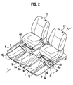
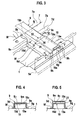
- Fig. 2 in conjunction with Figs. 1 and 3 shows a vehicle floor structure of a vehicle, of which only the center section in the region of two seat cross members 9, 9 is shown.
- the vehicle floor structure comprises two longitudinal members 7, 7, a center tunnel 3 in a floor panel 1 and two side sill assemblies 5, 5. Only a portion of a right one of the two side sill assemblies 5, 5 is shown in Fig. 2 . A portion of a left one of the two side sill assemblies 5, 5 is shown in Fig. 1 .
- the center tunnel 3 protrudes toward a passenger compartment 2 and runs or extends along the vehicle longitudinal center axis L-L (see Fig. 2 ).
- the center tunnel 3 holds the cross members 9, 9 so that they function as a single cross member between the two side sill assemblies 5, 5.
- a right longitudinal member 7 Disposed on the floor panel 1 between the right side sill assembly 5 and the center tunnel 3 is a right longitudinal member 7 that extends generally along the vehicle longitudinal center axis L-L.
- a left longitudinal member 7 Disposed on the floor panel 1 between the left side sill assembly 5 and the center tunnel 3 is a left longitudinal member 7 that extends generally along the vehicle longitudinal center axis L-L.
- the longitudinal members 7, 7 are rear extensions of two front side members, not shown, that extend rearwards from the front of the vehicle.
- the longitudinal members 7, 7 may be called front side member rear extensions.
- Each of the longitudinal members 7, 7 has a top wall 7a, two bent down side walls 7b, 7c from side edges of the top wall 7a, and downwardly facing laterally bent flanges 7d, 7e from bottom edges of the side walls 7b, 7c.
- the flanges 7d, 7e are fixedly connected to the floor panel 1.
- each of the longitudinal members 7, 7 has downwardly facing bent down legs 7b, 7d, and 7c, 7e connected to the floor panel 1.
- the two cross members 9, 9 of right and left are connected to the floor panel 1 on the right and left sides of the center tunnel 3. Stepping over the respective longitudinal members 7, 7, the cross members 9, 9 extend in the vehicle width direction. In other words, crossing the respective longitudinal members 7, 7, the cross members 9, 9 extend in the vehicle width direction.
- the cross member 9 passes, on a predetermined portion between outer and inner ends thereof, the longitudinal member 7. To avoid interference contact with the longitudinal member 7, the predetermined portion of the cross member 9 is cut upwardly from below to form a tunnel opening 9a that allows the passage of the longitudinal member 7.
- the cross member 9 has two flanges 9b extending along the vehicle longitudinal center axis L-L in the opposite directions from above the tunnel opening 9a. In Fig. 3 , only a front one 9b of the flanges is shown, but a rear one of the flanges is not shown. The front and rear flanges 9b are fixedly connected to a top wall 7a of the longitudinal member 7.
- Each of the cross members 9, 9 has a top wall 9c, two bent down side walls 9d, 9e from side edges of the top wall 9c, and downwardly facing bent flanges 9f, 9g (see Fig. 8 ) from bottom edges of the side walls 9d, 9e.
- the flanges 9f, 9g are fixedly connected to the floor panel 1.
- each of the cross members 9, 9 has downwardly facing bent down legs 9d, 9f, and 9e, 9g connected to the floor panel 1.
- each of the cross members 9, 9 has a flange 9h fixedly connected to a sill inner 5a of one of the side sill assemblies 5.
- each of the cross members 9, 9 has a flange 9i (see Fig. 2 ) fixedly connected to one of side walls 3a of the center tunnel 3.
- the side walls 3a slope downwards.
- the top wall 9c of each of cross member 9 is recessed at a predetermined area between the center tunnel 3 and the side sill assembly 5 to provide a recessed section 9j.
- the recessed section 9j of the top wall 9c is a flat top wall section 9j3.
- the flat top wall section 9j3 is lower in height than the two remaining sections of the top wall 9c which are not recessed.
- An inner one of the two remaining sections of the top wall 9c which are not recessed extends inwards from the inner end of the cross member 9 and connects into the recessed section 9j of the top wall 9c by way of an inner connecting portion 9j1, and an outer one thereof extends inwards from the outer end of the cross member 9 and connects into the recessed section 9j of the top wall 9c by way of an outer connecting portion 9j2.
- the inner connecting portion 9j1 includes a ramp between the top wall of the inner section of the top wall 9c which is not recessed and the flat top wall section 9j3 of the recessed section 9j. This ramp slopes downwards toward the flat top wall section 9j3 in a direction from the center tunnel 3 toward the side sill assembly 5.
- the outer connecting portion 9j2 includes a ramp between the top wall of the outer section of the top wall 9c which is not recessed and the flat top wall section 9j3 of the recessed section 9j. This ramp slopes downwards toward the flat top wall section 9j3 in a direction from the side sill assembly 5 toward the center tunnel 3.
- the inner connecting portion 9j1 is located between the longitudinal member 7 and the center tunnel 3, and the outer connecting portion is located between the longitudinal member 7 and the side sill assembly 5.
- the cross member 9 includes, between the longitudinal member 7 and the side sill assembly 5, the outer connecting portion 9j2 that divides the cross member 9 into two cross member portions (see Fig. 3 ).
- the two cross member portions include the remote cross member portion 32 from the outer end of the cross member 9 connected to the side sill assembly 5.
- This cross member portion 32 carries the top flat wall 9j3 of the recessed section 9j.
- the two cross member portions include the other cross member portion 34 adjacent to the side sill assembly 5.
- This cross member portion 34 carries the top wall 9c of the outer one of those remaining sections which are not recessed.
- the outer connecting portion 9j2 connects the remote cross member portion 32 and the other cross member portion 34 together.
- each cross member 9 with the above-mentioned recessed section 9j provides increased space under the associated one of seats 17 (see Fig. 2 ).
- the flat top wall section 9j3 of the remote cross member portion 32 is lower in height than the top wall of the other cross member portion 34. Because the ramp 36 slopes downwards toward the flat top wall section 9j3 in the direction from the side sill assembly 5 toward the center tunnel 3, the connecting portion 9j2 provides a transition in cross sectional profile between the different cross sectional profiles of the two cross member portions 32 and 34.
- each cross member 9 is another cross member 13.
- the associated seat 17 is installed via a seat slide mechanism 15 on the sections of the top wall 9c which are not recessed of the cross member and a top wall of the cross member 13.
- each cross member 9 is reinforced by an internal reinforcement element 19.
- the reinforcement element 19, within each cross member 9, extends through the connecting portion 9j2 into the remote cross member portion 32 and terminating in at its inner end 19b spaced by a gap 23 from a top wall 7a of the longitudinal member 7.
- the reinforcement element 19 is connected, on its top wall 19c, to an upper inner wall 9m of the remote cross member portion 32 to reinforce same.
- the reinforcement element 19 extends into the other cross member portion 34 and terminating in at its outer end 19a in the neighborhood of the side sill assembly 5 (see Fig. 1 ).
- the reinforcement element 19 is spaced from an upper inner wall 9n of the other cross member portion 34 to provide a gap 21.
- a center pillar (or a B-pillar) 20 extends upwardly from the side sill assembly 5.
- the center pillar 20 includes a pillar inner 20a and a pillar outer 20b. At its lower end portion, the pillar inner 20a is fixedly connected to a sill outer 5b of the side sill assembly 5.
- the cross member 9 and the center pillar 20 lie in the common transverse plane with respect to the longitudinal center axis L-L (see Fig. 2 ) of the vehicle.
- the reinforcement element 19 forms the gap 21 with the upper inner wall 9n of the other cross member portion 34 of the cross member 9 in approximately half of its entire length on the side of the outer end 19a, that is, the outer side of the connecting portion 9j2.
- the reinforcement element 19 has its outer end 19a disposed adjacent to the side sill assembly 5 and its top wall 19c spaced from the upper inner wall 9n of the cross member 9 on the side of its outer end 19a.
- the reinforcement element 19 forms a gap 23 (see Fig. 1 ) with the top wall 7a of the longitudinal member 7 on the side of the inner end 19b, that is, the inner side of the connecting portion 9j2. This means that the reinforcement element 19 has its inner end 19b spaced by a gap 23 from the top wall 7a of the longitudinal member 7.
- the reinforcement element 19 has a cross sectional profile of a vertically inversed U and includes bent down side walls 19d and 19e from the top wall 19c.
- the reinforcement element 19 has its top wall 19c fixedly connected to the upper inner wall 9m on the opposite side of the flat top wall section 9j3 on the inner side near the longitudinal member 7, that is, the inner side of the connecting portion 9j2. This means that the top wall 19c of the portion of the reinforcement element 19 on the side of the inner end 19b is fixedly connected to the upper inner wall 9m of the cross member 9 on the opposite side of the flat top wall 9j3.
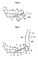
- a lower side impact load in the direction F1 of the arrow is applied to the side sill assembly 5 adjacent to the bottom end of the center pillar 20 in the event of a side collision.
- the lower impact load F1 acts on the cross member 9 and the reinforcement element 19 in their longitudinal direction.
- the illustration of the center pillar 20 and the sill outer 5b is hereby omitted.
- the cross member 9 is reinforced by the reinforcement element 19 to maintain the required setting level of strength.
- the cross member 9 and the reinforcement element 19 are spaced from each other to form the gap 21 on that portion which is disposed on the side of the side sill assembly 5.
- the strength of that cross member portion 34 of the cross member 9 which is spaced from the reinforcement element 19 does not rise too much so that the cross member portion 34 is compressed and broken in the longitudinal direction efficiently to absorb the impact energy.
- cross member 9 is stable enough, but has the cross member portion 34 which is compressed and broken in a longitudinal direction when the cross member 9 is stressed in the longitudinal direction by the lower side impact load F1 to absorb the impact energy in the event of a side collision.
- an upper side impact load in the direction F2 of the arrow is applied to the center pillar 20 at a portion above the side sill assembly 5 in the event of a side collision.
- the cross member 9 and the reinforcement element 19 are deformed and bent on that zone 25 where the cross member 9 and the reinforcement element 19 are fixedly connected to each other so that the portions of the cross member 9 and the reinforcement element 19 on the side of the side sill assembly 5 move upwardly, thereby to absorb the impact energy.
- the cross member 9 and the reinforcement element 19 are bent and deformed on that portion where the reinforcement element 19 is fixedly connected to the cross member 9 in such a direction to allow an upward movement of the side sill assembly 5 until the inner end 19b of the reinforcement element 19 contacts with the top wall 7a of the longitudinal member 7 when the cross member 9 is stressed in a rotational direction by the upper impact load F2 applied to the center pillar 20 above the side sill assembly 5 in the event of a side collision. Because further deformation and bending of the cross member 9 and the reinforcement element 19 end after the inner end 19b of the reinforcement element 19 contacts with the top wall 7a of the longitudinal member 7, a shape-locking connection is created to secure a space within the passenger compartment 2 in the event of a side collision.
- the cross member 9 is located under the passenger compartment 2 as high as the longitudinal member 7, which is a rear extension of a front side member, and the cross member 9 and the center pillar 20 lie in the common transverse plane with respect the vehicle longitudinal center axis L-L.
- the cross member 9 and the center pillar 20 lie in the common transverse plane with respect the vehicle longitudinal center axis L-L.
- the reinforcement element 19 is stiff enough to bear the load to restrain the deformation of the cross member 9. This suppresses the movement of the seat 17 along the vehicle longitudinal axis L-L (see Fig. 3 ) in the event of a front end collision.
Landscapes
- Engineering & Computer Science (AREA)
- Transportation (AREA)
- Mechanical Engineering (AREA)
- Chemical & Material Sciences (AREA)
- Combustion & Propulsion (AREA)
- Aviation & Aerospace Engineering (AREA)
- Body Structure For Vehicles (AREA)
Applications Claiming Priority (1)
| Application Number | Priority Date | Filing Date | Title |
|---|---|---|---|
| JP2007178399A JP4900095B2 (ja) | 2007-07-06 | 2007-07-06 | 自動車の車体フロア構造 |
Publications (3)
| Publication Number | Publication Date |
|---|---|
| EP2011719A2 true EP2011719A2 (de) | 2009-01-07 |
| EP2011719A3 EP2011719A3 (de) | 2009-06-24 |
| EP2011719B1 EP2011719B1 (de) | 2010-06-23 |
Family
ID=39683917
Family Applications (1)
| Application Number | Title | Priority Date | Filing Date |
|---|---|---|---|
| EP08011591A Active EP2011719B1 (de) | 2007-07-06 | 2008-06-26 | Bodenstruktur eines Kraftfahrzeugs |
Country Status (5)
| Country | Link |
|---|---|
| US (1) | US7644978B2 (de) |
| EP (1) | EP2011719B1 (de) |
| JP (1) | JP4900095B2 (de) |
| CN (1) | CN101337561B (de) |
| DE (1) | DE602008001580D1 (de) |
Cited By (5)
| Publication number | Priority date | Publication date | Assignee | Title |
|---|---|---|---|---|
| EP2487090A3 (de) * | 2011-02-11 | 2013-08-28 | Audi AG | Querträger eines Kraftfahrzeugs und Kraftfahrzeug mit einem solchen Querträger |
| EP2823928A4 (de) * | 2012-03-06 | 2015-07-08 | Jfe Steel Corp | Kopplungsstruktur |
| WO2016188802A1 (de) * | 2015-05-22 | 2016-12-01 | Bayerische Motoren Werke Aktiengesellschaft | Querträger für ein kraftfahrzeug |
| EP3578444A4 (de) * | 2017-03-10 | 2020-03-04 | Mazda Motor Corporation | Untere fahrzeugkarosseriestruktur für ein fahrzeug |
| FR3132072A1 (fr) * | 2022-01-26 | 2023-07-28 | Psa Automobiles Sa | Pièce structurelle déformable en cas de choc latéral, pour un véhicule |
Families Citing this family (42)
| Publication number | Priority date | Publication date | Assignee | Title |
|---|---|---|---|---|
| JP4407713B2 (ja) * | 2007-03-30 | 2010-02-03 | 日産自動車株式会社 | 車体構造 |
| US7854472B2 (en) * | 2007-10-22 | 2010-12-21 | Honda Motor Co., Ltd. | Vehicle body structure |
| US7828370B2 (en) * | 2007-10-25 | 2010-11-09 | Honda Motor Co., Ltd. | Vehicle body structure |
| DE102008009804A1 (de) * | 2008-02-19 | 2009-08-20 | Dr. Ing. H.C. F. Porsche Aktiengesellschaft | Bodenmittelteil einer Fahrzeugkarosserie |
| JP4690450B2 (ja) * | 2008-12-19 | 2011-06-01 | 本田技研工業株式会社 | 車体フロア構造 |
| DE102009042187A1 (de) * | 2009-09-18 | 2011-03-24 | Audi Ag | Fahrzeugkarosserieaufbau im Bodenbereich der Insassenkabine und zugeordnetes Fertigungsverfahren |
| US20130126254A1 (en) * | 2009-11-03 | 2013-05-23 | V-Ens Co., Ltd. | Motor vehicle |
| US8235459B2 (en) | 2010-04-07 | 2012-08-07 | Honda Motor Co., Ltd.. | Seat support assembly |
| CN101837754A (zh) * | 2010-05-25 | 2010-09-22 | 三一重机有限公司 | 一种矿用自卸车车厢底板加强筋结构 |
| FR2962967B1 (fr) * | 2010-07-23 | 2013-02-22 | Renault Sa | Chassis automobile avec renfort lateral de soutien d'assise |
| JP5585530B2 (ja) * | 2010-08-25 | 2014-09-10 | マツダ株式会社 | 車両の車体下部構造 |
| WO2012086297A1 (ja) * | 2010-12-24 | 2012-06-28 | 本田技研工業株式会社 | 自動車の車体構造 |
| JP5288054B1 (ja) * | 2011-09-01 | 2013-09-11 | トヨタ自動車株式会社 | 車体構造 |
| US9290208B2 (en) * | 2011-12-07 | 2016-03-22 | Toyota Jidosha Kabushiki Kaisha | Vehicle body lower portion structure |
| JP5776528B2 (ja) * | 2011-12-07 | 2015-09-09 | トヨタ自動車株式会社 | 車体のフロア構造 |
| US9290209B2 (en) * | 2012-03-29 | 2016-03-22 | Toyota Jidosha Kabushiki Kaisha | Vehicle body lower structure |
| JP6007643B2 (ja) * | 2012-07-30 | 2016-10-12 | マツダ株式会社 | 車両の上部車体構造 |
| JP5728523B2 (ja) * | 2013-04-17 | 2015-06-03 | 本田技研工業株式会社 | 車体構造 |
| KR101526397B1 (ko) * | 2013-12-18 | 2015-06-05 | 현대자동차 주식회사 | 차체 시트 장착부 보강구조 |
| US9114730B1 (en) * | 2014-02-19 | 2015-08-25 | International Truck Intellectual Property Company, Llc | Seat mounting structure in vehicle floor frame |
| FR3024421B1 (fr) * | 2014-08-04 | 2016-07-15 | Peugeot Citroen Automobiles Sa | Plancher avec traverse comprenant une portion rapportee deformable en compression |
| US9302715B2 (en) | 2014-09-10 | 2016-04-05 | Toyota Motor Engineering & Manufacturing North America, Inc. | Vehicles having side support reinforcement gussets |
| US9487243B2 (en) | 2014-12-09 | 2016-11-08 | Ford Global Technologies, Llc | Vehicle body structure |
| KR101714169B1 (ko) * | 2015-07-15 | 2017-03-08 | 현대자동차주식회사 | 차량의 플로어바디 |
| JP6319215B2 (ja) * | 2015-07-17 | 2018-05-09 | トヨタ自動車株式会社 | 車両骨格構造 |
| JP6398906B2 (ja) * | 2015-08-17 | 2018-10-03 | トヨタ自動車株式会社 | 車両側部構造 |
| JP6236428B2 (ja) * | 2015-10-22 | 2017-11-22 | 本田技研工業株式会社 | 車体側部構造 |
| WO2017098302A1 (en) * | 2015-12-09 | 2017-06-15 | Arcelormittal | Vehicle underbody structure comprising a reinforcement element between a longitudinal beam and a lowerside sill part |
| CN109789898B (zh) * | 2016-09-21 | 2021-10-12 | 本田技研工业株式会社 | 座椅安装构造 |
| JP6631474B2 (ja) * | 2016-11-08 | 2020-01-15 | トヨタ自動車株式会社 | 車両後部構造 |
| JP6919187B2 (ja) * | 2016-12-15 | 2021-08-18 | 三菱自動車工業株式会社 | 車体フロア構造 |
| JP6650920B2 (ja) * | 2017-12-14 | 2020-02-19 | 本田技研工業株式会社 | 車体のフロア構造 |
| KR102440612B1 (ko) * | 2017-12-15 | 2022-09-05 | 현대자동차 주식회사 | 측방 차체 보강구조 |
| JP6915592B2 (ja) * | 2018-06-15 | 2021-08-04 | マツダ株式会社 | 下部車体構造 |
| FR3082496B1 (fr) * | 2018-06-19 | 2020-08-21 | Psa Automobiles Sa | Chassis de vehicule automobile, pourvu d'une piece prenant des appuis antagonistes contre une traverse et un longeron en cas de choc lateral. |
| EP3828027A1 (de) * | 2019-11-27 | 2021-06-02 | MAGNA STEYR Fahrzeugtechnik AG & Co KG | Sitzmodul für ein kraftfahrzeug |
| JP2021094941A (ja) * | 2019-12-13 | 2021-06-24 | 本田技研工業株式会社 | フロア構造 |
| CN117042994B (zh) * | 2021-04-05 | 2024-06-18 | 日产自动车株式会社 | 高电压电子单元车载构造 |
| KR20230042805A (ko) * | 2021-09-23 | 2023-03-30 | 현대자동차주식회사 | 자동차용 멤버 조인트 장치 |
| KR20230097848A (ko) * | 2021-12-24 | 2023-07-03 | 현대자동차주식회사 | 차체의 어퍼 바디 구조 |
| JP2023152016A (ja) * | 2022-04-01 | 2023-10-16 | トヨタ自動車株式会社 | 車両底部構造 |
| JP7757863B2 (ja) * | 2022-04-05 | 2025-10-22 | マツダ株式会社 | 車両の下部車体構造 |
Citations (2)
| Publication number | Priority date | Publication date | Assignee | Title |
|---|---|---|---|---|
| JPH0880874A (ja) | 1994-09-14 | 1996-03-26 | Nissan Motor Co Ltd | 自動車の車体フロア構造 |
| JP2007178399A (ja) | 2005-12-28 | 2007-07-12 | Citizen Miyota Co Ltd | 振り子型センサ |
Family Cites Families (18)
| Publication number | Priority date | Publication date | Assignee | Title |
|---|---|---|---|---|
| US4514008A (en) * | 1981-06-05 | 1985-04-30 | Toyota Jidosha Kogyo Kabushiki Kaisha | Vehicle body floor construction of motor vehicle |
| JPH0450582A (ja) * | 1990-06-15 | 1992-02-19 | Tokin Corp | 開閉弁 |
| JPH06171551A (ja) * | 1992-12-11 | 1994-06-21 | Mazda Motor Corp | 自動車の下部車体構造 |
| JP3435910B2 (ja) * | 1995-07-13 | 2003-08-11 | 日産自動車株式会社 | 自動車の車体構造 |
| US6227610B1 (en) | 1998-02-19 | 2001-05-08 | Honda Giken Kogyo Kabushiki Kaisha | Cross member of an automobile body |
| DE19954296C2 (de) * | 1999-11-11 | 2003-06-18 | Porsche Ag | Fahrzeug |
| JP2001233254A (ja) * | 2000-02-22 | 2001-08-28 | Mitsubishi Automob Eng Co Ltd | 車体構造 |
| EP1186453B1 (de) * | 2000-08-19 | 2003-01-08 | Benteler Ag | Seitenaufprallträger |
| KR100405892B1 (ko) * | 2001-04-19 | 2003-11-14 | 기아자동차주식회사 | 측면 충돌에 대한 강성이 향상된 자동차의 플로어 패널조립체 |
| US6666501B1 (en) * | 2002-07-17 | 2003-12-23 | Daimlerchrysler Corporation | Lightweight automobile body structure |
| DE10232840A1 (de) | 2002-07-19 | 2004-02-05 | Volkswagen Ag | Bodenstruktur an Kraftfahrzeugen |
| JP3962003B2 (ja) * | 2003-10-16 | 2007-08-22 | 本田技研工業株式会社 | 車体構造 |
| EP1762465B1 (de) * | 2005-09-08 | 2009-07-01 | Ford Global Technologies, LLC | Aufprallschutzstruktur |
| JP4400548B2 (ja) * | 2005-11-02 | 2010-01-20 | トヨタ自動車株式会社 | 車体下部構造 |
| JP4747812B2 (ja) * | 2005-12-01 | 2011-08-17 | マツダ株式会社 | 車両の下部車体構造 |
| EP2006191B1 (de) * | 2007-06-19 | 2010-04-21 | Honda Motor Co., Ltd. | Fahrzeugaufbaubodenkonstruktion |
| US7854472B2 (en) * | 2007-10-22 | 2010-12-21 | Honda Motor Co., Ltd. | Vehicle body structure |
| US20090174220A1 (en) * | 2008-01-07 | 2009-07-09 | Gm Global Technology Operations, Inc. | Vehicle Body Structure with Linking Bracket for a Vehicle Side Pillar |
-
2007
- 2007-07-06 JP JP2007178399A patent/JP4900095B2/ja active Active
-
2008
- 2008-06-25 US US12/145,955 patent/US7644978B2/en active Active
- 2008-06-26 EP EP08011591A patent/EP2011719B1/de active Active
- 2008-06-26 DE DE602008001580T patent/DE602008001580D1/de active Active
- 2008-07-03 CN CN2008101318764A patent/CN101337561B/zh active Active
Patent Citations (3)
| Publication number | Priority date | Publication date | Assignee | Title |
|---|---|---|---|---|
| JPH0880874A (ja) | 1994-09-14 | 1996-03-26 | Nissan Motor Co Ltd | 自動車の車体フロア構造 |
| JP3381404B2 (ja) | 1994-09-14 | 2003-02-24 | 日産自動車株式会社 | 自動車の車体フロア構造 |
| JP2007178399A (ja) | 2005-12-28 | 2007-07-12 | Citizen Miyota Co Ltd | 振り子型センサ |
Cited By (7)
| Publication number | Priority date | Publication date | Assignee | Title |
|---|---|---|---|---|
| EP2487090A3 (de) * | 2011-02-11 | 2013-08-28 | Audi AG | Querträger eines Kraftfahrzeugs und Kraftfahrzeug mit einem solchen Querträger |
| EP2823928A4 (de) * | 2012-03-06 | 2015-07-08 | Jfe Steel Corp | Kopplungsstruktur |
| WO2016188802A1 (de) * | 2015-05-22 | 2016-12-01 | Bayerische Motoren Werke Aktiengesellschaft | Querträger für ein kraftfahrzeug |
| EP3578444A4 (de) * | 2017-03-10 | 2020-03-04 | Mazda Motor Corporation | Untere fahrzeugkarosseriestruktur für ein fahrzeug |
| US11077881B2 (en) | 2017-03-10 | 2021-08-03 | Mazda Motor Corporation | Lower vehicle body structure for vehicle |
| FR3132072A1 (fr) * | 2022-01-26 | 2023-07-28 | Psa Automobiles Sa | Pièce structurelle déformable en cas de choc latéral, pour un véhicule |
| WO2023144466A1 (fr) * | 2022-01-26 | 2023-08-03 | Psa Automobiles Sa | Pièce structurelle déformable en cas de choc latéral, pour un véhicule |
Also Published As
| Publication number | Publication date |
|---|---|
| US20090066118A1 (en) | 2009-03-12 |
| EP2011719B1 (de) | 2010-06-23 |
| JP4900095B2 (ja) | 2012-03-21 |
| CN101337561A (zh) | 2009-01-07 |
| CN101337561B (zh) | 2010-09-08 |
| EP2011719A3 (de) | 2009-06-24 |
| JP2009012674A (ja) | 2009-01-22 |
| US7644978B2 (en) | 2010-01-12 |
| DE602008001580D1 (de) | 2010-08-05 |
Similar Documents
| Publication | Publication Date | Title |
|---|---|---|
| EP2011719B1 (de) | Bodenstruktur eines Kraftfahrzeugs | |
| CN101654119B (zh) | 汽车的车架结构 | |
| CN109204547B (zh) | 用于车辆的车身结构 | |
| EP1927533B1 (de) | Seitenteilstruktur für eine Fahrzeugkarosserie | |
| CN110228534B (zh) | 车辆中柱 | |
| EP2783951A1 (de) | Umgebende struktur für eine fahrzeugkarosserie | |
| CN100408409C (zh) | 汽车下部车身结构 | |
| EP1812277B1 (de) | Anordnung für fahrzeugkabinen | |
| CN107097857A (zh) | 车身结构 | |
| CN112109601B (zh) | 包括车辆座椅轨道和支撑件的系统 | |
| US20160236717A1 (en) | Vehicle body lower portion structure | |
| CN111152850A (zh) | 车辆的下部车身结构 | |
| JP4483843B2 (ja) | 車体骨格フレームの補強構造 | |
| CN104024090A (zh) | 支柱结构 | |
| US20190276089A1 (en) | Center pillar structure | |
| JP2009012703A (ja) | 自動車の車体構造 | |
| JP2005247002A (ja) | センタピラー構造 | |
| JP4997914B2 (ja) | ドア構造 | |
| JP2000177631A (ja) | 自動車の側部車体構造 | |
| JP5246543B2 (ja) | 車両用内装材の組み付け構造 | |
| JP3828324B2 (ja) | 自動車の車体構造 | |
| EP2428432A1 (de) | Vorderseitenchassis einer Fahrzeugkarosserie | |
| WO2026014085A1 (ja) | 車体構造部材 | |
| JP5815260B2 (ja) | 車体側部の衝撃緩衝構造 | |
| JP5724927B2 (ja) | 車体上部構造 |
Legal Events
| Date | Code | Title | Description |
|---|---|---|---|
| PUAI | Public reference made under article 153(3) epc to a published international application that has entered the european phase |
Free format text: ORIGINAL CODE: 0009012 |
|
| 17P | Request for examination filed |
Effective date: 20080626 |
|
| AK | Designated contracting states |
Kind code of ref document: A2 Designated state(s): AT BE BG CH CY CZ DE DK EE ES FI FR GB GR HR HU IE IS IT LI LT LU LV MC MT NL NO PL PT RO SE SI SK TR |
|
| AX | Request for extension of the european patent |
Extension state: AL BA MK RS |
|
| PUAL | Search report despatched |
Free format text: ORIGINAL CODE: 0009013 |
|
| AK | Designated contracting states |
Kind code of ref document: A3 Designated state(s): AT BE BG CH CY CZ DE DK EE ES FI FR GB GR HR HU IE IS IT LI LT LU LV MC MT NL NO PL PT RO SE SI SK TR |
|
| AX | Request for extension of the european patent |
Extension state: AL BA MK RS |
|
| GRAP | Despatch of communication of intention to grant a patent |
Free format text: ORIGINAL CODE: EPIDOSNIGR1 |
|
| AKX | Designation fees paid |
Designated state(s): DE FR GB |
|
| GRAS | Grant fee paid |
Free format text: ORIGINAL CODE: EPIDOSNIGR3 |
|
| GRAA | (expected) grant |
Free format text: ORIGINAL CODE: 0009210 |
|
| AK | Designated contracting states |
Kind code of ref document: B1 Designated state(s): DE FR GB |
|
| REF | Corresponds to: |
Ref document number: 602008001580 Country of ref document: DE Date of ref document: 20100805 Kind code of ref document: P |
|
| PLBE | No opposition filed within time limit |
Free format text: ORIGINAL CODE: 0009261 |
|
| STAA | Information on the status of an ep patent application or granted ep patent |
Free format text: STATUS: NO OPPOSITION FILED WITHIN TIME LIMIT |
|
| 26N | No opposition filed |
Effective date: 20110324 |
|
| REG | Reference to a national code |
Ref country code: DE Ref legal event code: R097 Ref document number: 602008001580 Country of ref document: DE Effective date: 20110323 |
|
| REG | Reference to a national code |
Ref country code: FR Ref legal event code: PLFP Year of fee payment: 9 |
|
| REG | Reference to a national code |
Ref country code: FR Ref legal event code: PLFP Year of fee payment: 10 |
|
| REG | Reference to a national code |
Ref country code: FR Ref legal event code: PLFP Year of fee payment: 11 |
|
| REG | Reference to a national code |
Ref country code: DE Ref legal event code: R084 Ref document number: 602008001580 Country of ref document: DE |
|
| REG | Reference to a national code |
Ref country code: GB Ref legal event code: 746 Effective date: 20230925 |
|
| PGFP | Annual fee paid to national office [announced via postgrant information from national office to epo] |
Ref country code: DE Payment date: 20250520 Year of fee payment: 18 |
|
| PGFP | Annual fee paid to national office [announced via postgrant information from national office to epo] |
Ref country code: GB Payment date: 20250520 Year of fee payment: 18 |
|
| PGFP | Annual fee paid to national office [announced via postgrant information from national office to epo] |
Ref country code: FR Payment date: 20250520 Year of fee payment: 18 |