EP2011736A2 - Werkstückträger, ausgebildet als Kunststoffbehälter - Google Patents
Werkstückträger, ausgebildet als Kunststoffbehälter Download PDFInfo
- Publication number
- EP2011736A2 EP2011736A2 EP08007806A EP08007806A EP2011736A2 EP 2011736 A2 EP2011736 A2 EP 2011736A2 EP 08007806 A EP08007806 A EP 08007806A EP 08007806 A EP08007806 A EP 08007806A EP 2011736 A2 EP2011736 A2 EP 2011736A2
- Authority
- EP
- European Patent Office
- Prior art keywords
- workpiece carrier
- container
- carrier according
- support rib
- webs
- Prior art date
- Legal status (The legal status is an assumption and is not a legal conclusion. Google has not performed a legal analysis and makes no representation as to the accuracy of the status listed.)
- Granted
Links
- 239000004033 plastic Substances 0.000 title claims description 5
- 238000001746 injection moulding Methods 0.000 claims abstract description 4
- 238000000465 moulding Methods 0.000 claims abstract 2
- 238000004519 manufacturing process Methods 0.000 description 3
- 239000000969 carrier Substances 0.000 description 2
- 238000005452 bending Methods 0.000 description 1
- 230000004907 flux Effects 0.000 description 1
- 230000003993 interaction Effects 0.000 description 1
- 239000002991 molded plastic Substances 0.000 description 1
- 239000002689 soil Substances 0.000 description 1
Images

Classifications
-
- B—PERFORMING OPERATIONS; TRANSPORTING
- B65—CONVEYING; PACKING; STORING; HANDLING THIN OR FILAMENTARY MATERIAL
- B65D—CONTAINERS FOR STORAGE OR TRANSPORT OF ARTICLES OR MATERIALS, e.g. BAGS, BARRELS, BOTTLES, BOXES, CANS, CARTONS, CRATES, DRUMS, JARS, TANKS, HOPPERS, FORWARDING CONTAINERS; ACCESSORIES, CLOSURES, OR FITTINGS THEREFOR; PACKAGING ELEMENTS; PACKAGES
- B65D1/00—Rigid or semi-rigid containers having bodies formed in one piece, e.g. by casting metallic material, by moulding plastics, by blowing vitreous material, by throwing ceramic material, by moulding pulped fibrous material or by deep-drawing operations performed on sheet material
- B65D1/22—Boxes or like containers with side walls of substantial depth for enclosing contents
- B65D1/24—Boxes or like containers with side walls of substantial depth for enclosing contents with moulded compartments or partitions
Definitions
- the invention relates to a workpiece carrier, designed as a plastic container, in particular made in one piece by injection molding, which has arranged for centering of the recorded workpieces bottom-side mold cavities.
- a workpiece carrier of this kind is through the DE 36 30 566 C2 known. It is used for the internal transport of workpieces or assembly parts as well as for the transport of these parts from the manufacturing plant to the assembly plant and the supply of workpieces for automatically loaded assembly machines.
- the stored workpieces are in this case by projections and / or depressions, ie centered by mold cavities, which allows both automated handling and safe transport, in which the individual workpieces should not touch.
- the known workpiece carrier is made of two plastic parts and consists of a frame and a plate provided with the mold cavities (openings and / or depressions and / or projections) plate.
- the deep-drawn or injection-molded plastic sheet is thereby slipped over the frame and thus simultaneously increases the stability of the workpiece carrier.
- the invention is therefore an object of the invention to provide a generic workpiece carrier without the disadvantages mentioned above, which in particular offers a much higher stability with simple production and prevents damage to the invited contents or the workpieces.
- At least one support rib is provided which bridges the distance between two opposite container walls and extending in height, starting from the container bottom almost flush with the upper edge of the container upwards. This can be achieved that during transport and storage when stacking filled workpiece carriers, the bottoms of each upper workpiece carrier does not come into contact with the workpieces, but rest on the support rib, so that no damage can occur to the sensitive contents.
- both the container bottom and the container walls molded, thin or flat plate-like support rib increases the stability of the workpiece carrier or container because the linear flux of force collected during stacking and further prevents bending of the soil or . is reduced.
- the stability of the workpiece carrier and the interception of the forces occurring can be further increased or improve. Both the support rib and the support webs continue to contribute to the sensitive contents is protected and the individual workpieces can not touch.
- Advantageous embodiments of the invention provide that the support rib and the support webs arranged at its two longitudinal sides stiffening struts, z. B. in the form of a web or closed profile or a hollow body profile are formed.
- stiffening struts are arranged offset from one another, and are preferably issued with a wedge-shaped course from top to bottom.
- the stability-increasing stiffening struts form with the compared to the wall-bridging support rib far less wide support webs literally Vase support segments.
- the resulting inner cohesion of all workpiece carrier elements contributes to the overall rigidity and stability.
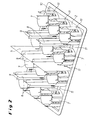
- FIG. 1 illustrated workpiece carrier 1 in rectangular container design is made in one piece by injection molding of plastic and has a closed bottom 2 and longitudinal walls 3 and end walls 4.
- a narrow, plate-like support rib 5 bridges the distance between the two longitudinal walls 3 and is molded onto this and the container bottom 2.
- the support rib 5 extends almost flush with the container or workpiece carrier upper edge finally upwards.
- On the container bottom 2 are formed for centering of recorded or invited, not shown workpieces in adjacent rows each form nests 7, which here have a circular or annular contour.
- Fig. 2 how closer the Fig. 2 can be seen, are interspersed between the mold cavities 7 and distributed arranged a plurality of the container bottom 2 upwardly projecting support webs 8, which are compared to the support rib 5 of only small width, based on the container transverse axis.
- Both the support rib 5 and the support webs 8 are provided with over the entire height extending, provided on both longitudinal sides, orthogonal thereto and thus extending in the container longitudinal direction, staggered stiffening struts 9 provided.
- staggered stiffening struts 9 provided. Especially in the interaction of the stiffening struts 9 with the support webs 8 results in local, Hererielige support segments.
- For internal rigidity and rigidity contributes that the mold cavities 7 are connected to each other and with the support rib 5 and the support webs 8 and a bottom inner edge 10 via bottom webs 11 and connected.
Landscapes
- Engineering & Computer Science (AREA)
- Ceramic Engineering (AREA)
- Mechanical Engineering (AREA)
- Moulds For Moulding Plastics Or The Like (AREA)
- Containers Having Bodies Formed In One Piece (AREA)
- Packaging Of Annular Or Rod-Shaped Articles, Wearing Apparel, Cassettes, Or The Like (AREA)
- Details Of Rigid Or Semi-Rigid Containers (AREA)
- Processing And Handling Of Plastics And Other Materials For Molding In General (AREA)
Abstract
Description
- Die Erfindung betrifft einen Werkstückträger, ausgebildet als Kunststoffbehälter, insbesondere einstückig hergestellt durch Spritzgießen, der zur Zentrierung der aufgenommenen Werkstücke bodenseitig angeordnete Formnester aufweist.
- Ein Werkstückträger dieser Art ist durch die
DE 36 30 566 C2 bekannt geworden. Er dient für den innerbetrieblichen Transport von Werkstücken bzw. Montageteilen sowie auch für den Transport dieser Teile vom Herstellungswerk zum Montagewerk und der Zuführung von Werkstücken zur automatisch beschickten Montagemaschinen. Die eingelagerten Werkstücke werden hierbei durch Vorsprünge und/oder Vertiefungen, d.h. von Formnestern zentriert, was sowohl ein automatisiertes Handling als auch einen sicheren Transport ermöglicht, bei dem sich die einzelnen Werkstücke nicht berühren sollen. - Der bekannte Werkstückträger ist aus zwei Kunststoffteilen gefertigt und besteht aus einem Rahmen und aus einer mit den Formnestern (Durchbrüche und/oder Vertiefungen und/oder Vorsprünge) versehenen Platte. Die aus Kunststofffolie tief gezogene oder im Spritzgussverfahren hergestellte Platte wird dabei über den Rahmen gestülpt und erhöht somit gleichzeitig die Stabilität des Werkstückträgers.
- Abgesehen davon, daß die Herstellung dieser Werkstückträger mit mehreren Arbeitsgängen verbunden und somit aufwendig ist, tritt trotz der Überstülpplatte ein Verzug auf, insbesondere beim automatisierten Be- und Entladen der Werkstückträger. Eine sichere Lagerung und ein sicherer Transport kann damit nicht mehr gewährleistet werden.
- Der Erfindung liegt daher die Aufgabe zugrunde, einen gattungsgemäßen Werkstückträger ohne die genannten Nachteile zu schaffen, der bei einfacher Herstellung insbesondere eine deutlich höhere Stabilität bietet und Beschädigungen an dem eingeladenen Füllgut bzw. den Werkstücken verhindert.
- Diese Aufgabe wird erfindungsgemäß dadurch gelöst, daß mindestens eine Stützrippe vorgesehen ist, die den Abstand zwischen zwei einander gegenüberliegenden Behälterwänden überbrückt und sich in der Höhe ausgehend vom Behälterboden bis nahezu bündig mit dem Behälteroberrand abschließend nach oben erstreckt. Damit lässt sich erreichen, daß während des Transportes und der Lagerung beim Aufeinanderstapeln von gefüllten Werkstückträgern die Böden der jeweils oberen Werkstückträger nicht mit den Werkstücken in Berührung kommen, sondern auf der Stützrippe aufliegen, so daß an dem sensiblen Füllgut keine Beschädigungen auftreten können. Gleichzeitig erhöht die nach einer vorteilhaften Ausführung der Erfindung sowohl am Behälterboden als auch an den Behälterwänden angespritzte, dünne bzw. flache plattenartige Stützrippe die Stabilität des Werkstückträgers bzw. -behälters, weil der lineare Kraftfluss beim Aufeinanderstapeln aufgefangen und weiterhin auch eine Durchbiegung des Bodens verhindert bzw. verringert wird.
- Wenn vorzugsweise zwischen den Formnestern, die je nach Inhaltsgut unterschiedlich ausgebildet sind, verteilt angeordnete, vom Behälterboden, an den sie sich vorteilhaft sogleich anspritzen lassen, aus hochragende Stützstege vorgesehen sind, lässt sich die Stabilität des Werkstückträgers und das Auffangen der auftretenden Kräfte noch weiter erhöhen bzw. verbessern. Sowohl die Stützrippe als auch die Stützstege tragen weiterhin dazu bei, daß das sensible Inhaltsgut geschützt wird und sich die einzelnen Werkstücke nicht berühren können. Vorteilhafte Ausgestaltungen der Erfindung sehen vor, daß die Stützrippe und auch die Stützstege mit an ihren beiden Längsseiten angeordneten Versteifungsstreben, z. B. in Form eines Steges bzw. geschlossenen Profils oder eines Hohlkörperprofils, ausgebildet sind.
- Es wird vorgeschlagen, daß die Versteifungsstreben zueinander versetzt angeordnet sind, und vorzugsweise mit von oben nach unten keilförmigem Verlauf ausgestellt sind. Die stabilitätserhöhenden Versteifungsstreben bilden mit den im Vergleich zu der wandüberbrückenden Stützrippe weit weniger breiten Stützstegen regelrecht mehrflügelige Stützsegmente.
- Nach einem weiteren Vorschlag der Erfindung sind die Formnester einerseits untereinander und mit der Stützrippe sowie den Stützstegen und andererseits mit einem Bodeninnenrand über Bodenflachstege verbunden. Der damit erreichte innere Zusammenhalt aller Werkstückträgerelemente trägt zur Gesamtsteifigkeit und Stabilität bei.
- Weitere Merkmale und Einzelheiten der Erfindung ergeben sich aus den Ansprüchen und der nachfolgenden Beschreibung eines in den Zeichnungen dargestellten Ausführungsbeispiels der Erfindung. Es zeigen:
-
Fig. 1 einen Werkstückträger in einer perspektivischen Draufsicht in das Behälterinnere mit den dort ausgebildeten Formnestern und einer von Wand zu Wand reichenden Stützrippe sowie mehreren Stützstegen; und -
Fig. 2 in einer perspektivischen Gesamtansicht als Einzelheit den Behälterboden mit den darauf ausgebildeten Formnestern einschließlich Stützrippe und Stützstegen. - Ein im Ausführungsbeispiel nach
Fig. 1 dargestellter Werkstückträger 1 in rechteckiger Behälterbauweise ist einstückig durch Spitzgießen aus Kunststoff hergestellt und weist einen geschlossenen Boden 2 sowie Längswände 3 und Stirnwände 4 auf. Eine schmale, plattenartige Stützrippe 5 überbrückt den Abstand zwischen den beiden Längswänden 3 und ist an diesen sowie am Behälterboden 2 angespritzt. Die Stützrippe 5 erstreckt sich bis nahezu bündig mit dem Behälter- bzw. Werkstückträgeroberrand abschließend nach oben. Auf dem Behälterboden 2 sind zur Zentrierung von aufgenommenen bzw. eingeladenen, nicht dargestellten Werkstücken in nebeneinander liegenden Reihen jeweils Formnester 7 ausgebildet, die hier eine kreis- bzw. ringförmige Kontur besitzen. - Wie sich näher der
Fig. 2 entnehmen lässt, sind zwischen den Formnestern 7 eingestreut bzw. verteilt angeordnet mehrere vom Behälterboden 2 nach oben ragende Stützstege 8 vorgesehen, die im Vergleich zur Stützrippe 5 von nur geringer Breite, bezogen auf die Behälterquerachse, sind. Sowohl die Stützrippe 5 als auch die Stützstege 8 sind mit sich über deren gesamte Höhe erstreckenden, an beiden Längsseiten vorgesehenen, dazu orthogonal und somit in Behälterlängsrichtung verlaufenden, zueinander versetzten Versteifungsstreben 9 versehen. Vor allem im Zusammenspiel der Versteifungsstreben 9 mit den Stützstegen 8 ergeben sich lokale, mehrflügelige Stützsegmente. Zur inneren Steifigkeit und Starrheit trägt bei, daß die Formnester 7 untereinander und mit der Stützrippe 5 sowie den Stützstegen 8 und mit einem Bodeninnenrand 10 über Bodenflachstege 11 verbunden bzw. angebunden sind. -
- 1
- Werkstückträger
- 2
- Behälterboden
- 3
- Längswand
- 4
- Stirnwand
- 5
- Stützrippe
- 6
- Behälter-/Werkstückträgeroberrand
- 7
- Formnest
- 8
- Stützsteg
- 9
- Versteifungsstrebe
- 10
- Bodeninnenrand
- 11
- Bodenflachsteg
Claims (10)
- Werkstückträger (1), ausgebildet als Kunststoffbehälter, insbesondere einstückig hergestellt durch Spritzgießen, der zur Zentrierung der aufgenommenen Werkstücke bodenseitig angeordnete Formnester (7) aufweist,
dadurch gekennzeichnet,
daß mindestens eine Stützrippe (5) vorgesehen ist, die den Abstand zwischen zwei einander gegenüberliegenden Behälterwänden (3) überbrückt und sich in der Höhe ausgehend vom Behälterboden (2) bis nahezu bündig mit dem Behälteroberrand (6) abschließend nach oben erstreckt. - Werkstückträger nach Anspruch 1,
dadurch gekennzeichnet,
daß die Stützrippe (5) mit an ihren beiden Längsseiten verteilt angeordneten Versteifungsstreben (9) ausgebildet ist. - Werkstückträger nach Anspruch 2,
dadurch gekennzeichnet,
daß die Versteifungsstreben (9) zueinander versetzt angeordnet sind. - Werkstückträger nach einem der Ansprüche 1 bis 3,
dadurch gekennzeichnet,
daß die Stützrippe (5) sowohl am Behälterboden (2) als auch an den Behälterwänden (3) angespritzt ist. - Werkstückträger nach einem der Ansprüche 1 bis 4,
dadurch gekennzeichnet,
daß die Versteifungsstreben (9) mit von der Stützrippenoberkante zum Behälterboden (2) keilförmigem Verlauf ausgestellt sind. - Werkstückträger nach einem der Ansprüche 1 bis 5,
gekennzeichnet durch
zwischen den Formnestern (7) verteilt angeordnete, vom Behälterboden (2) aus hochragende Stützstege (8). - Werkstückträger nach Anspruch 6,
dadurch gekennzeichnet,
daß die Stützstege (8) an ihren beiden Längsseiten zumindest jeweils eine Versteifungsstrebe (9) aufweisen. - Werkstückträger nach Anspruch 7,
dadurch gekennzeichnet,
daß die Versteifungsstreben (9) zueinander versetzt angeordnet sind. - Werkstückträger nach einem der Ansprüche 6 bis 8,
dadurch gekennzeichnet,
daß die Stützstege (8) am Behälterboden (2) angespritzt sind. - Werkstückträger nach einem der Ansprüche 1 bis 9,
dadurch gekennzeichnet,
daß die Formnester (7) einerseits untereinander und mit der Stützrippe (5) sowie den Stützstegen (8) und andererseits mit einem Bodeninnenrand (10) über Bodenflachstege (11) verbunden sind.
Applications Claiming Priority (1)
| Application Number | Priority Date | Filing Date | Title |
|---|---|---|---|
| DE202007009469U DE202007009469U1 (de) | 2007-07-05 | 2007-07-05 | Werkstückträger, ausgebildet als Kunststoffbehälter |
Publications (3)
| Publication Number | Publication Date |
|---|---|
| EP2011736A2 true EP2011736A2 (de) | 2009-01-07 |
| EP2011736A3 EP2011736A3 (de) | 2009-08-12 |
| EP2011736B1 EP2011736B1 (de) | 2010-11-17 |
Family
ID=39134846
Family Applications (1)
| Application Number | Title | Priority Date | Filing Date |
|---|---|---|---|
| EP08007806A Not-in-force EP2011736B1 (de) | 2007-07-05 | 2008-04-23 | Werkstückträger, ausgebildet als Kunststoffbehälter |
Country Status (3)
| Country | Link |
|---|---|
| EP (1) | EP2011736B1 (de) |
| AT (1) | ATE488436T1 (de) |
| DE (2) | DE202007009469U1 (de) |
Citations (1)
| Publication number | Priority date | Publication date | Assignee | Title |
|---|---|---|---|---|
| DE3630566C2 (de) | 1986-09-09 | 1995-11-09 | Stucki Kunststoffwerk | Werkstückträger |
Family Cites Families (3)
| Publication number | Priority date | Publication date | Assignee | Title |
|---|---|---|---|---|
| US6186345B1 (en) * | 1998-10-21 | 2001-02-13 | Display Industires, Llc. | Stackable shipping case having gravity feed tracks |
| EP1060996A3 (de) * | 1999-06-04 | 2007-02-28 | Oberland Engineering GmbH, Entwicklung und Patente | Kasten |
| DE202004010991U1 (de) * | 2004-07-14 | 2004-10-07 | SCHäFER WERKE GMBH | Transportkasten |
-
2007
- 2007-07-05 DE DE202007009469U patent/DE202007009469U1/de not_active Expired - Lifetime
-
2008
- 2008-04-23 DE DE502008001801T patent/DE502008001801D1/de active Active
- 2008-04-23 AT AT08007806T patent/ATE488436T1/de active
- 2008-04-23 EP EP08007806A patent/EP2011736B1/de not_active Not-in-force
Patent Citations (1)
| Publication number | Priority date | Publication date | Assignee | Title |
|---|---|---|---|---|
| DE3630566C2 (de) | 1986-09-09 | 1995-11-09 | Stucki Kunststoffwerk | Werkstückträger |
Also Published As
| Publication number | Publication date |
|---|---|
| DE502008001801D1 (de) | 2010-12-30 |
| EP2011736A3 (de) | 2009-08-12 |
| ATE488436T1 (de) | 2010-12-15 |
| DE202007009469U1 (de) | 2008-02-28 |
| EP2011736B1 (de) | 2010-11-17 |
Similar Documents
| Publication | Publication Date | Title |
|---|---|---|
| EP3354589B1 (de) | Haltestruktur zum gleichzeitigen halten einer mehrzahl von behältern für substanzen für pharmazeutische, medizinische oder kosmetische anwendungen, transportgebilde und transport- oder verpackungsbehälter mit selbiger | |
| EP2686035B1 (de) | Trägerplatte und transport- und/oder lagereinrichtung für pharmazeutische behältnisse | |
| EP0411391B1 (de) | Transportpalette | |
| DE102009027454A1 (de) | Aufnahmebehälter für pharmazeutische Behältnisse | |
| EP2251184A1 (de) | Verfahren zur Herstellung eines Transport- und Lagermittels sowie ein zur Durchführung des Verfahrens ausgebildetes Transport- und Lagermittel | |
| EP3650366A1 (de) | Einsatz für einen behälter und behältersystem mit derartigem einsatz | |
| EP2070842B1 (de) | Werkstückträger, ausgebildet als Kunststoffbehälter | |
| DE2549400C3 (de) | Kunststoffbehälter | |
| EP0601494B1 (de) | Stirnwand aus Spritzgussmaterial für eine Wickelfolie | |
| EP3656693B1 (de) | Vorrichtung zum transport von stückgütern | |
| EP3377416B1 (de) | Behälter aus kunststoff | |
| EP2011736B1 (de) | Werkstückträger, ausgebildet als Kunststoffbehälter | |
| EP0259672A1 (de) | Werkstückträger | |
| EP0512289A1 (de) | Flaschenkasten aus Kunststoff mit Flaschenklemmung | |
| AT393442B (de) | Karussellboden fuer eckschraenke | |
| EP4532380A1 (de) | Transportsystem und verwendung eines kunststofftablars für ein transportsystem | |
| EP0208062B1 (de) | Behälter für eine Mehrzahl scheibenförmiger Gegenstände und Behälterteil davon | |
| DE3827207A1 (de) | Behaelter aus tiefziehmaterial | |
| EP0277307B1 (de) | Transport-, Lager- und Stapelvorrichtung | |
| DE9111352U1 (de) | Anzucht-, Transport- und Verkaufssteige | |
| DE102016006620A1 (de) | Vorrichtung zur Aufnahme von kleinen Bauteilen für die Prozessschritte Transport, Reinigung und Automatisierung | |
| EP0585535B1 (de) | Stapelkasten aus Kunststoff | |
| DE2602489C3 (de) | Flaschenkasten aus Kunststoff | |
| DE202008012489U1 (de) | Behälter zur Aufnahme von gleichartigen Gegenständen | |
| DE202004014340U1 (de) | Drehstapelbehälter |
Legal Events
| Date | Code | Title | Description |
|---|---|---|---|
| PUAI | Public reference made under article 153(3) epc to a published international application that has entered the european phase |
Free format text: ORIGINAL CODE: 0009012 |
|
| AK | Designated contracting states |
Kind code of ref document: A2 Designated state(s): AT BE BG CH CY CZ DE DK EE ES FI FR GB GR HR HU IE IS IT LI LT LU LV MC MT NL NO PL PT RO SE SI SK TR |
|
| AX | Request for extension of the european patent |
Extension state: AL BA MK RS |
|
| PUAL | Search report despatched |
Free format text: ORIGINAL CODE: 0009013 |
|
| AK | Designated contracting states |
Kind code of ref document: A3 Designated state(s): AT BE BG CH CY CZ DE DK EE ES FI FR GB GR HR HU IE IS IT LI LT LU LV MC MT NL NO PL PT RO SE SI SK TR |
|
| AX | Request for extension of the european patent |
Extension state: AL BA MK RS |
|
| 17P | Request for examination filed |
Effective date: 20100112 |
|
| AKX | Designation fees paid |
Designated state(s): AT BE BG CH CY CZ DE DK EE ES FI FR GB GR HR HU IE IS IT LI LT LU LV MC MT NL NO PL PT RO SE SI SK TR |
|
| RIC1 | Information provided on ipc code assigned before grant |
Ipc: B65D 1/24 20060101AFI20100316BHEP |
|
| GRAP | Despatch of communication of intention to grant a patent |
Free format text: ORIGINAL CODE: EPIDOSNIGR1 |
|
| GRAS | Grant fee paid |
Free format text: ORIGINAL CODE: EPIDOSNIGR3 |
|
| GRAA | (expected) grant |
Free format text: ORIGINAL CODE: 0009210 |
|
| AK | Designated contracting states |
Kind code of ref document: B1 Designated state(s): AT BE BG CH CY CZ DE DK EE ES FI FR GB GR HR HU IE IS IT LI LT LU LV MC MT NL NO PL PT RO SE SI SK TR |
|
| REG | Reference to a national code |
Ref country code: GB Ref legal event code: FG4D Free format text: NOT ENGLISH |
|
| REG | Reference to a national code |
Ref country code: CH Ref legal event code: EP |
|
| REG | Reference to a national code |
Ref country code: IE Ref legal event code: FG4D |
|
| REF | Corresponds to: |
Ref document number: 502008001801 Country of ref document: DE Date of ref document: 20101230 Kind code of ref document: P |
|
| REG | Reference to a national code |
Ref country code: NL Ref legal event code: VDEP Effective date: 20101117 |
|
| LTIE | Lt: invalidation of european patent or patent extension |
Effective date: 20101117 |
|
| PG25 | Lapsed in a contracting state [announced via postgrant information from national office to epo] |
Ref country code: LT Free format text: LAPSE BECAUSE OF FAILURE TO SUBMIT A TRANSLATION OF THE DESCRIPTION OR TO PAY THE FEE WITHIN THE PRESCRIBED TIME-LIMIT Effective date: 20101117 Ref country code: NO Free format text: LAPSE BECAUSE OF FAILURE TO SUBMIT A TRANSLATION OF THE DESCRIPTION OR TO PAY THE FEE WITHIN THE PRESCRIBED TIME-LIMIT Effective date: 20110217 |
|
| PG25 | Lapsed in a contracting state [announced via postgrant information from national office to epo] |
Ref country code: BG Free format text: LAPSE BECAUSE OF FAILURE TO SUBMIT A TRANSLATION OF THE DESCRIPTION OR TO PAY THE FEE WITHIN THE PRESCRIBED TIME-LIMIT Effective date: 20110217 Ref country code: NL Free format text: LAPSE BECAUSE OF FAILURE TO SUBMIT A TRANSLATION OF THE DESCRIPTION OR TO PAY THE FEE WITHIN THE PRESCRIBED TIME-LIMIT Effective date: 20101117 Ref country code: FI Free format text: LAPSE BECAUSE OF FAILURE TO SUBMIT A TRANSLATION OF THE DESCRIPTION OR TO PAY THE FEE WITHIN THE PRESCRIBED TIME-LIMIT Effective date: 20101117 Ref country code: SE Free format text: LAPSE BECAUSE OF FAILURE TO SUBMIT A TRANSLATION OF THE DESCRIPTION OR TO PAY THE FEE WITHIN THE PRESCRIBED TIME-LIMIT Effective date: 20101117 Ref country code: IS Free format text: LAPSE BECAUSE OF FAILURE TO SUBMIT A TRANSLATION OF THE DESCRIPTION OR TO PAY THE FEE WITHIN THE PRESCRIBED TIME-LIMIT Effective date: 20110317 Ref country code: SI Free format text: LAPSE BECAUSE OF FAILURE TO SUBMIT A TRANSLATION OF THE DESCRIPTION OR TO PAY THE FEE WITHIN THE PRESCRIBED TIME-LIMIT Effective date: 20101117 Ref country code: LV Free format text: LAPSE BECAUSE OF FAILURE TO SUBMIT A TRANSLATION OF THE DESCRIPTION OR TO PAY THE FEE WITHIN THE PRESCRIBED TIME-LIMIT Effective date: 20101117 Ref country code: CY Free format text: LAPSE BECAUSE OF FAILURE TO SUBMIT A TRANSLATION OF THE DESCRIPTION OR TO PAY THE FEE WITHIN THE PRESCRIBED TIME-LIMIT Effective date: 20101117 Ref country code: PT Free format text: LAPSE BECAUSE OF FAILURE TO SUBMIT A TRANSLATION OF THE DESCRIPTION OR TO PAY THE FEE WITHIN THE PRESCRIBED TIME-LIMIT Effective date: 20110317 Ref country code: HR Free format text: LAPSE BECAUSE OF FAILURE TO SUBMIT A TRANSLATION OF THE DESCRIPTION OR TO PAY THE FEE WITHIN THE PRESCRIBED TIME-LIMIT Effective date: 20101117 |
|
| REG | Reference to a national code |
Ref country code: IE Ref legal event code: FD4D |
|
| REG | Reference to a national code |
Ref country code: HU Ref legal event code: AG4A Ref document number: E010348 Country of ref document: HU |
|
| PG25 | Lapsed in a contracting state [announced via postgrant information from national office to epo] |
Ref country code: GR Free format text: LAPSE BECAUSE OF FAILURE TO SUBMIT A TRANSLATION OF THE DESCRIPTION OR TO PAY THE FEE WITHIN THE PRESCRIBED TIME-LIMIT Effective date: 20110218 |
|
| PG25 | Lapsed in a contracting state [announced via postgrant information from national office to epo] |
Ref country code: ES Free format text: LAPSE BECAUSE OF FAILURE TO SUBMIT A TRANSLATION OF THE DESCRIPTION OR TO PAY THE FEE WITHIN THE PRESCRIBED TIME-LIMIT Effective date: 20110228 Ref country code: CZ Free format text: LAPSE BECAUSE OF FAILURE TO SUBMIT A TRANSLATION OF THE DESCRIPTION OR TO PAY THE FEE WITHIN THE PRESCRIBED TIME-LIMIT Effective date: 20101117 Ref country code: IE Free format text: LAPSE BECAUSE OF FAILURE TO SUBMIT A TRANSLATION OF THE DESCRIPTION OR TO PAY THE FEE WITHIN THE PRESCRIBED TIME-LIMIT Effective date: 20101117 Ref country code: EE Free format text: LAPSE BECAUSE OF FAILURE TO SUBMIT A TRANSLATION OF THE DESCRIPTION OR TO PAY THE FEE WITHIN THE PRESCRIBED TIME-LIMIT Effective date: 20101117 |
|
| PG25 | Lapsed in a contracting state [announced via postgrant information from national office to epo] |
Ref country code: DK Free format text: LAPSE BECAUSE OF FAILURE TO SUBMIT A TRANSLATION OF THE DESCRIPTION OR TO PAY THE FEE WITHIN THE PRESCRIBED TIME-LIMIT Effective date: 20101117 Ref country code: PL Free format text: LAPSE BECAUSE OF FAILURE TO SUBMIT A TRANSLATION OF THE DESCRIPTION OR TO PAY THE FEE WITHIN THE PRESCRIBED TIME-LIMIT Effective date: 20101117 Ref country code: RO Free format text: LAPSE BECAUSE OF FAILURE TO SUBMIT A TRANSLATION OF THE DESCRIPTION OR TO PAY THE FEE WITHIN THE PRESCRIBED TIME-LIMIT Effective date: 20101117 Ref country code: SK Free format text: LAPSE BECAUSE OF FAILURE TO SUBMIT A TRANSLATION OF THE DESCRIPTION OR TO PAY THE FEE WITHIN THE PRESCRIBED TIME-LIMIT Effective date: 20101117 |
|
| PLBE | No opposition filed within time limit |
Free format text: ORIGINAL CODE: 0009261 |
|
| STAA | Information on the status of an ep patent application or granted ep patent |
Free format text: STATUS: NO OPPOSITION FILED WITHIN TIME LIMIT |
|
| 26N | No opposition filed |
Effective date: 20110818 |
|
| BERE | Be: lapsed |
Owner name: FRITZ SCHAFER G.M.B.H. Effective date: 20110430 |
|
| PG25 | Lapsed in a contracting state [announced via postgrant information from national office to epo] |
Ref country code: MC Free format text: LAPSE BECAUSE OF NON-PAYMENT OF DUE FEES Effective date: 20110430 |
|
| REG | Reference to a national code |
Ref country code: DE Ref legal event code: R097 Ref document number: 502008001801 Country of ref document: DE Effective date: 20110818 |
|
| PG25 | Lapsed in a contracting state [announced via postgrant information from national office to epo] |
Ref country code: IT Free format text: LAPSE BECAUSE OF FAILURE TO SUBMIT A TRANSLATION OF THE DESCRIPTION OR TO PAY THE FEE WITHIN THE PRESCRIBED TIME-LIMIT Effective date: 20101117 Ref country code: MT Free format text: LAPSE BECAUSE OF FAILURE TO SUBMIT A TRANSLATION OF THE DESCRIPTION OR TO PAY THE FEE WITHIN THE PRESCRIBED TIME-LIMIT Effective date: 20101117 |
|
| PG25 | Lapsed in a contracting state [announced via postgrant information from national office to epo] |
Ref country code: BE Free format text: LAPSE BECAUSE OF NON-PAYMENT OF DUE FEES Effective date: 20110430 |
|
| REG | Reference to a national code |
Ref country code: CH Ref legal event code: PL |
|
| GBPC | Gb: european patent ceased through non-payment of renewal fee |
Effective date: 20120423 |
|
| PG25 | Lapsed in a contracting state [announced via postgrant information from national office to epo] |
Ref country code: LI Free format text: LAPSE BECAUSE OF NON-PAYMENT OF DUE FEES Effective date: 20120430 Ref country code: GB Free format text: LAPSE BECAUSE OF NON-PAYMENT OF DUE FEES Effective date: 20120423 Ref country code: CH Free format text: LAPSE BECAUSE OF NON-PAYMENT OF DUE FEES Effective date: 20120430 |
|
| PG25 | Lapsed in a contracting state [announced via postgrant information from national office to epo] |
Ref country code: LU Free format text: LAPSE BECAUSE OF NON-PAYMENT OF DUE FEES Effective date: 20110423 |
|
| PG25 | Lapsed in a contracting state [announced via postgrant information from national office to epo] |
Ref country code: TR Free format text: LAPSE BECAUSE OF FAILURE TO SUBMIT A TRANSLATION OF THE DESCRIPTION OR TO PAY THE FEE WITHIN THE PRESCRIBED TIME-LIMIT Effective date: 20101117 |
|
| REG | Reference to a national code |
Ref country code: AT Ref legal event code: MM01 Ref document number: 488436 Country of ref document: AT Kind code of ref document: T Effective date: 20130423 |
|
| PG25 | Lapsed in a contracting state [announced via postgrant information from national office to epo] |
Ref country code: AT Free format text: LAPSE BECAUSE OF NON-PAYMENT OF DUE FEES Effective date: 20130423 |
|
| REG | Reference to a national code |
Ref country code: FR Ref legal event code: PLFP Year of fee payment: 9 |
|
| REG | Reference to a national code |
Ref country code: FR Ref legal event code: PLFP Year of fee payment: 10 |
|
| REG | Reference to a national code |
Ref country code: FR Ref legal event code: PLFP Year of fee payment: 11 |
|
| PGFP | Annual fee paid to national office [announced via postgrant information from national office to epo] |
Ref country code: HU Payment date: 20190415 Year of fee payment: 12 Ref country code: FR Payment date: 20190424 Year of fee payment: 12 |
|
| PGFP | Annual fee paid to national office [announced via postgrant information from national office to epo] |
Ref country code: DE Payment date: 20200420 Year of fee payment: 13 |
|
| PG25 | Lapsed in a contracting state [announced via postgrant information from national office to epo] |
Ref country code: HU Free format text: LAPSE BECAUSE OF NON-PAYMENT OF DUE FEES Effective date: 20200424 Ref country code: FR Free format text: LAPSE BECAUSE OF NON-PAYMENT OF DUE FEES Effective date: 20200430 |
|
| REG | Reference to a national code |
Ref country code: DE Ref legal event code: R119 Ref document number: 502008001801 Country of ref document: DE |
|
| PG25 | Lapsed in a contracting state [announced via postgrant information from national office to epo] |
Ref country code: DE Free format text: LAPSE BECAUSE OF NON-PAYMENT OF DUE FEES Effective date: 20211103 |