EP2011938A1 - Dispositif de connexion avec boulon pour connecter sélectivement deux composants - Google Patents
Dispositif de connexion avec boulon pour connecter sélectivement deux composants Download PDFInfo
- Publication number
- EP2011938A1 EP2011938A1 EP08159586A EP08159586A EP2011938A1 EP 2011938 A1 EP2011938 A1 EP 2011938A1 EP 08159586 A EP08159586 A EP 08159586A EP 08159586 A EP08159586 A EP 08159586A EP 2011938 A1 EP2011938 A1 EP 2011938A1
- Authority
- EP
- European Patent Office
- Prior art keywords
- reloading
- bolt
- ferromagnetic
- components
- stable
- Prior art date
- Legal status (The legal status is an assumption and is not a legal conclusion. Google has not performed a legal analysis and makes no representation as to the accuracy of the status listed.)
- Withdrawn
Links
- 230000002452 interceptive effect Effects 0.000 claims abstract 2
- 230000005294 ferromagnetic effect Effects 0.000 claims description 31
- 230000000694 effects Effects 0.000 claims description 13
- 230000005291 magnetic effect Effects 0.000 claims description 9
- 239000003302 ferromagnetic material Substances 0.000 description 3
- 238000000926 separation method Methods 0.000 description 2
- 238000007792 addition Methods 0.000 description 1
- 230000008878 coupling Effects 0.000 description 1
- 238000010168 coupling process Methods 0.000 description 1
- 238000005859 coupling reaction Methods 0.000 description 1
- 230000001419 dependent effect Effects 0.000 description 1
- 230000004048 modification Effects 0.000 description 1
- 238000012986 modification Methods 0.000 description 1
- 239000002023 wood Substances 0.000 description 1
Images

Classifications
-
- E—FIXED CONSTRUCTIONS
- E05—LOCKS; KEYS; WINDOW OR DOOR FITTINGS; SAFES
- E05B—LOCKS; ACCESSORIES THEREFOR; HANDCUFFS
- E05B47/00—Operating or controlling locks or other fastening devices by electric or magnetic means
- E05B47/0038—Operating or controlling locks or other fastening devices by electric or magnetic means using permanent magnets
-
- E—FIXED CONSTRUCTIONS
- E05—LOCKS; KEYS; WINDOW OR DOOR FITTINGS; SAFES
- E05B—LOCKS; ACCESSORIES THEREFOR; HANDCUFFS
- E05B17/00—Accessories in connection with locks
- E05B17/20—Means independent of the locking mechanism for preventing unauthorised opening, e.g. for securing the bolt in the fastening position
- E05B17/2007—Securing, deadlocking or "dogging" the bolt in the fastening position
-
- E—FIXED CONSTRUCTIONS
- E05—LOCKS; KEYS; WINDOW OR DOOR FITTINGS; SAFES
- E05B—LOCKS; ACCESSORIES THEREFOR; HANDCUFFS
- E05B15/00—Other details of locks; Parts for engagement by bolts of fastening devices
- E05B15/0053—Other details of locks; Parts for engagement by bolts of fastening devices means providing a stable, i.e. indexed, position of lock parts
-
- E—FIXED CONSTRUCTIONS
- E05—LOCKS; KEYS; WINDOW OR DOOR FITTINGS; SAFES
- E05B—LOCKS; ACCESSORIES THEREFOR; HANDCUFFS
- E05B15/00—Other details of locks; Parts for engagement by bolts of fastening devices
- E05B15/10—Bolts of locks or night latches
- E05B15/101—Spring-retracted bolts
-
- E—FIXED CONSTRUCTIONS
- E05—LOCKS; KEYS; WINDOW OR DOOR FITTINGS; SAFES
- E05B—LOCKS; ACCESSORIES THEREFOR; HANDCUFFS
- E05B15/00—Other details of locks; Parts for engagement by bolts of fastening devices
- E05B15/04—Spring arrangements in locks
- E05B2015/0448—Units of springs; Two or more springs working together
-
- E—FIXED CONSTRUCTIONS
- E05—LOCKS; KEYS; WINDOW OR DOOR FITTINGS; SAFES
- E05C—BOLTS OR FASTENING DEVICES FOR WINGS, SPECIALLY FOR DOORS OR WINDOWS
- E05C1/00—Fastening devices with bolts moving rectilinearly
- E05C1/08—Fastening devices with bolts moving rectilinearly with latching action
Definitions
- the present invention concerns a connection device with a bolt to selectively connect two components, preferably but not only used in the furnishing field, in order to make up and/or take apart furniture components, such as for example wood paneling, covers, shelves, backs, doors or other components.
- connection device with bolt is known, with a magnetic command, like the one described in GB-A-2,145,461 .
- Another purpose is to prevent the use of costly components, such as permanent magnets inside the device.
- the Applicant has devised, tested and embodied the present invention to overcome the shortcomings of the state of the art and to obtain these and other purposes and advantages.
- a connection device is used to connect two components, and comprises a containing element, able to be coupled with a first of the two components to be connected, and a bolt element able to cooperate with the second of the two components.
- the bolt element is axially slidable inside the containing element and is normally positioned in a first position, active and stable, which prepares the connection device for the connection of the two components. In fact, in the first position the bolt element at least partly protrudes from the containing element and can be inserted into the second of the two components to be connected, or into an element connected therewith.
- the bolt element is axially mobile, inside the reloading element, due to the effect of a second elastic element interposed between them, so that, in its active position, it can be temporarily and elastically inserted in the containing element, applying an axial thrust thereon.
- connection device also comprises a ferromagnetic element, that is, at least partly made of ferromagnetic material, which is able to clamp the reloading element.
- the ferromagnetic element is constantly thrust by a third elastic element against the reloading element and kept in a clamping position, corresponding to the reloading position.
- the ferromagnetic element is also mobile inside the containing element and movable to a release position, corresponding to the reloading position due to the effect of an external magnetic field.
- a stop element is associated with the reloading element, able to cooperate with the ferromagnetic element.
- the bolt element When it is switched to the active position, the bolt element is kept stably in said position.
- the stop element is inserted into a corresponding cavity or recess of the ferromagnetic element and clamps the stop element stably, together with the reloading element.
- the bolt element when a magnetic element is brought near to the connection device, the bolt element is automatically switched from its active position to its inactive position. This switching occurs because the ferromagnetic element, subjected to an action of magnetic attraction greater than the elastic thrust exerted by the third elastic element acting thereon, is moved from its initial position. In this way the stop element associated with the reloading element exits from the cavity of the ferromagnetic element and the reloading element, thrust by the first elastic element, is moved with respect to the containing element.
- the reloading element draws the bolt element with it, which is thus retracted inside the containing element, and remains in this position even after the magnet has been distanced, due to the effect of the force exerted on the reloading element by said first elastic element.
- the bolt element is able to be moved manually to the active position, by thrusting the reloading element axially toward the inside of the containing element.
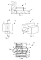
- connection device 10 is used to selectively connect two components 11a and 11b such as for example furnishing elements.
- connection device 10 comprises a containing element 12 having a lower surface 17 ( fig. 4 ) able to rest on and be attached to the component 11a.
- a bolt element 13 Inside the containing element 12, a bolt element 13, a reloading element 14 and a ferromagnetic element 15 are disposed.
- the reloading element 14 slides axially inside the containing element 12 and the bolt element 13 slides axially with respect to the reloading element 14.
- the bolt element 13 comprises a wedge end 13a and is selectively positionable between a first position, active and stable, in which the wedge end 13a protrudes from the containing element 12 and can be inserted into the component 1 b, and a second position, inactive and stable, in which the wedge end 13a is retracted inside the containing element 12.
- the axial sliding of the reloading element 14 ( fig. 4 ), between a loading position corresponding to the first position of the bolt element 13, and a reloading position, corresponding to the second position, is elastically contrasted by the action of a first helical spring 20 acting between an internal wall of the containing element 12 and the reloading element 14 itself.
- the reloading element 14 comprises a stop tooth 16 able to cooperate with the ferromagnetic element 15.
- the axial sliding of the bolt element 13 inside the reloading element 14 occurs due to the effect of the action of a second helical spring 21. Therefore, by applying an axial thrust on the wedge end 13a of the bolt element 13 it is possible to determine the elastic movement of the latter from its first position to its second position.
- the switching of the bolt element 13 from the first to the second position occurs by bringing an actuation magnet near to the connection device 10 in proximity with the ferromagnetic element 15. Following this movement, an action of magnetic attraction is produced on the ferromagnetic element 15 which overcomes the elastic thrust normally exerted by the third helical spring 25. In this way, the ferromagnetic element 15 is attracted toward the lower wall of the containing element 12 and moved to a release position, causing the relative emergence of the stop tooth 16 of the reloading element 14 from the cavity 18 of the ferromagnetic element 15.
- the switching of the bolt element 13 from the second position to the first position occurs by axially thrusting the rod 14a of the reloading element 14 from outside the containing element 12 until the elastic action exerted by the first helical spring 20 is overcome.
- the reloading element 14 is moved until it reaches a position in which the stop tooth 16 is positioned in correspondence with the cavity 18 of the ferromagnetic element 15.
- the ferromagnetic element 15 is thrust toward the reloading element 14.
- the stop tooth 16 of the reloading element 14 is inserted into the cavity 18 of the ferromagnetic element 15 and stably clamped in this position due to the effect of the third helical spring 25. Consequently, the bolt element 13 is also thrust by the reloading element 14 until it is switched to the first position.
- connection device 10 With reference to fig. 7 , where the parts not described are identical to those reported in the previous drawings, a variant of the connection device 10 according to the present invention is shown.
- the stop tooth 16 is associated with the ferromagnetic element 15 and cooperates with the cavity 18 made in the reloading element 14.
- the ferromagnetic element 15 is cylindrical in shape and is able to slide in a direction substantially orthogonal to the direction of sliding of the bolt element 13, inside a cylindrical guide 32 of the containing element 12.
- connection device 10 as described heretofore, without departing from the field and scope of the present invention.
Landscapes
- Flanged Joints, Insulating Joints, And Other Joints (AREA)
- Seal Device For Vehicle (AREA)
- Handcart (AREA)
- Details Of Connecting Devices For Male And Female Coupling (AREA)
Applications Claiming Priority (1)
| Application Number | Priority Date | Filing Date | Title |
|---|---|---|---|
| IT000123A ITUD20070123A1 (it) | 2007-07-05 | 2007-07-05 | Dispositivo di collegamento a chiavistello per collegare selettivamente due componenti |
Publications (1)
| Publication Number | Publication Date |
|---|---|
| EP2011938A1 true EP2011938A1 (fr) | 2009-01-07 |
Family
ID=39787873
Family Applications (1)
| Application Number | Title | Priority Date | Filing Date |
|---|---|---|---|
| EP08159586A Withdrawn EP2011938A1 (fr) | 2007-07-05 | 2008-07-03 | Dispositif de connexion avec boulon pour connecter sélectivement deux composants |
Country Status (2)
| Country | Link |
|---|---|
| EP (1) | EP2011938A1 (fr) |
| IT (1) | ITUD20070123A1 (fr) |
Cited By (4)
| Publication number | Priority date | Publication date | Assignee | Title |
|---|---|---|---|---|
| US20160145906A1 (en) * | 2014-11-24 | 2016-05-26 | Taiwan Fu Hsing Industrial Co., Ltd. | Latch assembly |
| US20220178392A1 (en) * | 2019-03-29 | 2022-06-09 | L-Acoustics | Enclosure fastening module |
| FR3156115A1 (fr) * | 2023-12-01 | 2025-06-06 | Airbus Operations (S.A.S.) | Dispositif d’accrochage amovible d’un panneau sur une structure porteuse |
| EP4733522A1 (fr) * | 2024-10-24 | 2026-04-29 | Tecniplast S.p.A. | Verrou et cage comportant ce verrou |
Citations (5)
| Publication number | Priority date | Publication date | Assignee | Title |
|---|---|---|---|---|
| FR981307A (fr) * | 1948-12-28 | 1951-05-24 | Système de verrouillage, en particulier pour portes, couvercles et similaires | |
| US4293154A (en) * | 1979-09-28 | 1981-10-06 | Cassells Melvin K | Safety lock for window sashes and the like |
| GB2145461A (en) | 1983-08-22 | 1985-03-27 | Roger Conington Richards | Magnetically operated latch |
| US5386713A (en) * | 1991-03-07 | 1995-02-07 | Wilson; Bert | Remote control car deadbolt lock |
| WO2006064260A1 (fr) * | 2004-12-18 | 2006-06-22 | Giovanni Maria Laporta | Systeme de serrure de chassis |
-
2007
- 2007-07-05 IT IT000123A patent/ITUD20070123A1/it unknown
-
2008
- 2008-07-03 EP EP08159586A patent/EP2011938A1/fr not_active Withdrawn
Patent Citations (5)
| Publication number | Priority date | Publication date | Assignee | Title |
|---|---|---|---|---|
| FR981307A (fr) * | 1948-12-28 | 1951-05-24 | Système de verrouillage, en particulier pour portes, couvercles et similaires | |
| US4293154A (en) * | 1979-09-28 | 1981-10-06 | Cassells Melvin K | Safety lock for window sashes and the like |
| GB2145461A (en) | 1983-08-22 | 1985-03-27 | Roger Conington Richards | Magnetically operated latch |
| US5386713A (en) * | 1991-03-07 | 1995-02-07 | Wilson; Bert | Remote control car deadbolt lock |
| WO2006064260A1 (fr) * | 2004-12-18 | 2006-06-22 | Giovanni Maria Laporta | Systeme de serrure de chassis |
Cited By (5)
| Publication number | Priority date | Publication date | Assignee | Title |
|---|---|---|---|---|
| US20160145906A1 (en) * | 2014-11-24 | 2016-05-26 | Taiwan Fu Hsing Industrial Co., Ltd. | Latch assembly |
| US10060160B2 (en) * | 2014-11-24 | 2018-08-28 | Taiwan Fu Hsing Industrial Co., Ltd. | Latch assembly |
| US20220178392A1 (en) * | 2019-03-29 | 2022-06-09 | L-Acoustics | Enclosure fastening module |
| FR3156115A1 (fr) * | 2023-12-01 | 2025-06-06 | Airbus Operations (S.A.S.) | Dispositif d’accrochage amovible d’un panneau sur une structure porteuse |
| EP4733522A1 (fr) * | 2024-10-24 | 2026-04-29 | Tecniplast S.p.A. | Verrou et cage comportant ce verrou |
Also Published As
| Publication number | Publication date |
|---|---|
| ITUD20070123A1 (it) | 2009-01-06 |
Similar Documents
| Publication | Publication Date | Title |
|---|---|---|
| US9416805B2 (en) | Solenoid coupling with electrical pulse release | |
| EP2011938A1 (fr) | Dispositif de connexion avec boulon pour connecter sélectivement deux composants | |
| EP3148304A2 (fr) | Ensemble rail coulissant et son dispositif de support | |
| EP4512445A3 (fr) | Tige de piston et système d'ensemble seringue | |
| EP3398481A1 (fr) | Ensemble de rails de glissement | |
| JP2017035517A5 (fr) | ||
| EP4616890A3 (fr) | Ensemble d'administration pour un dispositif d'administration de médicament et dispositif d'administration de médicament le comprenant | |
| EP4365470A3 (fr) | Ensemble de suspension | |
| MX2024001292A (es) | Acoplador rapido. | |
| EP2428473B1 (fr) | Séparateur doté d'un engrenage à coulisses | |
| US20190383068A1 (en) | Locking device and sliding door with locking device | |
| US6041992A (en) | Portable device for inserting into predetermined seats in a body, such as an item of furniture, fixing and/or support elements for load-bearing members associated with said body, such as support feet for the item of furniture | |
| CN105986722A (zh) | 低噪音移动的加速和减速装置 | |
| US8640783B2 (en) | Solenoid interlock for booster actuator | |
| US20120073119A1 (en) | Method for Applying Magnets | |
| US20180031015A1 (en) | Clip holding and release device | |
| JP2017538877A (ja) | スライディングドアの戸のための減衰または戻り装置 | |
| DE102014112337A1 (de) | Greifvorrichtung | |
| EP2428472B1 (fr) | Séparateur doté d'un actionneur électrodynamique | |
| CN107046251A (zh) | 引线夹持装置 | |
| CN106996762B (zh) | 具有捕获装置的改换机构 | |
| EP4595821A3 (fr) | Dispositif pour fixer de manière amovible une arme | |
| US9455076B2 (en) | Coupling with solenoid release locking mechanism | |
| US20180014643A1 (en) | Slide rail assembly | |
| CN109160239B (zh) | 定位结构及具有其的输送设备 |
Legal Events
| Date | Code | Title | Description |
|---|---|---|---|
| PUAI | Public reference made under article 153(3) epc to a published international application that has entered the european phase |
Free format text: ORIGINAL CODE: 0009012 |
|
| AK | Designated contracting states |
Kind code of ref document: A1 Designated state(s): AT BE BG CH CY CZ DE DK EE ES FI FR GB GR HR HU IE IS IT LI LT LU LV MC MT NL NO PL PT RO SE SI SK TR |
|
| AX | Request for extension of the european patent |
Extension state: AL BA MK RS |
|
| AKX | Designation fees paid | ||
| REG | Reference to a national code |
Ref country code: DE Ref legal event code: 8566 |
|
| STAA | Information on the status of an ep patent application or granted ep patent |
Free format text: STATUS: THE APPLICATION IS DEEMED TO BE WITHDRAWN |
|
| 18D | Application deemed to be withdrawn |
Effective date: 20090708 |