EP2011948A2 - Eckverbinder für Tür- und Fensterrahmen - Google Patents
Eckverbinder für Tür- und Fensterrahmen Download PDFInfo
- Publication number
- EP2011948A2 EP2011948A2 EP08011189A EP08011189A EP2011948A2 EP 2011948 A2 EP2011948 A2 EP 2011948A2 EP 08011189 A EP08011189 A EP 08011189A EP 08011189 A EP08011189 A EP 08011189A EP 2011948 A2 EP2011948 A2 EP 2011948A2
- Authority
- EP
- European Patent Office
- Prior art keywords
- spreading
- corner connector
- spreading device
- hollow profile
- inclined surface
- Prior art date
- Legal status (The legal status is an assumption and is not a legal conclusion. Google has not performed a legal analysis and makes no representation as to the accuracy of the status listed.)
- Withdrawn
Links
- 230000037431 insertion Effects 0.000 claims abstract description 3
- 238000003780 insertion Methods 0.000 claims abstract description 3
- 239000000243 solution Substances 0.000 description 4
- 230000003014 reinforcing effect Effects 0.000 description 2
- 238000003466 welding Methods 0.000 description 2
- 229910000831 Steel Inorganic materials 0.000 description 1
- 230000007423 decrease Effects 0.000 description 1
- 238000006073 displacement reaction Methods 0.000 description 1
- 230000000694 effects Effects 0.000 description 1
- 230000002996 emotional effect Effects 0.000 description 1
- 238000001746 injection moulding Methods 0.000 description 1
- 230000001788 irregular Effects 0.000 description 1
- 238000004519 manufacturing process Methods 0.000 description 1
- 239000002184 metal Substances 0.000 description 1
- 239000010959 steel Substances 0.000 description 1
- 239000003351 stiffener Substances 0.000 description 1
Images

Classifications
-
- E—FIXED CONSTRUCTIONS
- E06—DOORS, WINDOWS, SHUTTERS, OR ROLLER BLINDS IN GENERAL; LADDERS
- E06B—FIXED OR MOVABLE CLOSURES FOR OPENINGS IN BUILDINGS, VEHICLES, FENCES OR LIKE ENCLOSURES IN GENERAL, e.g. DOORS, WINDOWS, BLINDS, GATES
- E06B3/00—Window sashes, door leaves, or like elements for closing wall or like openings; Layout of fixed or moving closures, e.g. windows in wall or like openings; Features of rigidly-mounted outer frames relating to the mounting of wing frames
- E06B3/96—Corner joints or edge joints for windows, doors, or the like frames or wings
- E06B3/964—Corner joints or edge joints for windows, doors, or the like frames or wings using separate connection pieces, e.g. T-connection pieces
- E06B3/968—Corner joints or edge joints for windows, doors, or the like frames or wings using separate connection pieces, e.g. T-connection pieces characterised by the way the connecting pieces are fixed in or on the frame members
- E06B3/972—Corner joints or edge joints for windows, doors, or the like frames or wings using separate connection pieces, e.g. T-connection pieces characterised by the way the connecting pieces are fixed in or on the frame members by increasing the cross-section of the connecting pieces, e.g. by expanding the connecting pieces with wedges
- E06B3/9725—Mitre joints
-
- E—FIXED CONSTRUCTIONS
- E06—DOORS, WINDOWS, SHUTTERS, OR ROLLER BLINDS IN GENERAL; LADDERS
- E06B—FIXED OR MOVABLE CLOSURES FOR OPENINGS IN BUILDINGS, VEHICLES, FENCES OR LIKE ENCLOSURES IN GENERAL, e.g. DOORS, WINDOWS, BLINDS, GATES
- E06B3/00—Window sashes, door leaves, or like elements for closing wall or like openings; Layout of fixed or moving closures, e.g. windows in wall or like openings; Features of rigidly-mounted outer frames relating to the mounting of wing frames
- E06B3/96—Corner joints or edge joints for windows, doors, or the like frames or wings
- E06B3/9604—Welded or soldered joints
- E06B3/9608—Mitre joints
Definitions
- the invention relates to a corner connector for door and window frames, with a rectangular cross-section shank for insertion into a mitered frame hollow section and the shaft final, weldable or glued, according to the miter of the hollow profile extending inclined surface and a spreading of a The spreading of the rectangular surfaces of the shaft spreading device for clamping the shaft in the hollow profile.
- Such corner connectors are known in numerous embodiments.
- An expanding wedge is used by the applicant by means of a screw screwed in from the inclined surface over an inclined surface of the shank.
- the expanding wedge increases, so that it braces in the interior of the hollow profile.
- the wedge forms a spreading part, which increases the cross-section of the corner connector and thereby reaches the tension.
- the DE 91 13 235 U1 shows a corner connector, which also has a wedge as a spreading, but this is not pushed by means of a screw, but one of the wedge directly molded tongue in the corner connector or pulled out of this.
- the Applicant described a solution in which between the wedge-shaped expansion part and the inner surface of the hollow profile is a pressure plate which is pressed by the expansion part to the outside and ensures that the wedge is displaced in its longitudinal displacement on the always same inner surface of the printing plate, so that the tensile or compressive force with which the wedge has been moved is always a measure of the tension achieved.
- a disadvantage of this known solution is that the injection molding tool to be used is relatively expensive and the corner connector is accordingly expensive.
- the invention is therefore an object of the invention to provide a corner connector of the type mentioned, which can be produced with relatively simple tools, so that the production costs are relatively low.
- the spreading device is designed as a studded band and that the expansion part on the side facing the spreading device has dome-shaped recesses which engage over the knobs.
- the knobs migrate to the edges of the respective associated dome-shaped cavities, the expansion part is pressed from the shaft, so that the shaft is clamped in the hollow profile.
- the expansion part can be pressed both directly against the inner surface of the hollow profile, as well as a pressure plate, as shown in the aforementioned European font.
- the nubs are preferably formed substantially hemispherical.
- the rounding to the tension side prevents the knobs get caught in the dome-shaped recesses of the expansion.
- the rounding on both sides allow a lateral tilting of the expansion part, so that this can adapt to the inner profile of the hollow sections, which differ in their dimensions relative to the standard.
- a plurality of knobs are arranged in a row on the drawstring, so that distribute the forces that must be applied for lifting the expansion, over the entire length of the drawstring.
- the drawstring at its front ie the end directed to the inclined surface have an eyelet, which is located in a recessed recess of the inclined surface and can be detected here with a tool.
- This tool can be designed so that it is supported on the miter surface of the hollow profile when exercising the tensile force and thus ensures that the corner connector, if it is set in motion of the tensile force in the direction out of the hollow profile in motion, by the tool is held in a flush position with respect to the hollow profile.
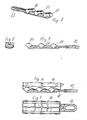
- Fig. 1 shows a corner connector according to the invention.
- the corner connector has a rectangular cross-section shaft 10, which is closed by an inclined surface 12.
- the inclined surface 12 serves as a welding surface which is welded to a corresponding offset by 90 ° arranged welding surface of another corner connector.
- the shaft 10 is inserted into a hollow profile of a window or door frame.
- the hollow profile is stiffened by a square tube 14 made of metal, which is inserted into the window hollow profile.
- This stiffening profile 14 is not cut mitred, but just cut off.
- the corner connector is located directly in this stiffening profile 14th
- the corner connector according to the invention has on the upper side of the shaft, a spreader 16 which upwards in Fig. 1 can be raised and clamped in this way the shaft 10 in the hollow profile, more precisely in the stiffening profile 14.
- a spreading device 18 is provided, which has the shape of a tension band with a series of knobs 20,22,24.
- the knobs 20,22,24 form substantially hemispherical elevations of the inherently flat band. It may also be semi-cylindrical ribs, as shown in the drawing.
- the spreading device or the band 18 can be pulled out of the corner connector to the right. This will be explained later in detail.
- the knobs When moving to the right in Fig. 1 the knobs move 20,22,24 along the bottom of dome-shaped recesses 26,28,30. Since the inner height of the dome-shaped recesses decreases towards the edges, the spreading member 16, while the tension band, which forms the spreading device 18 is pulled to the right, gradually raised. As a result, the corner connector is clamped in the hollow profile.
- the knobs 20,22,24 not return within the dome-shaped recesses 26,28,30, the surfaces of the knobs and the recesses are formed in a suitable manner self-locking, as indicated in the drawing by the illustrated zig-zag profile.
- the drawstring which forms the spreading device 18, is provided at its right end with an eyelet 32.
- the eyelet 32 can be detected from the outside of the inclined surface 12 forth with a suitable tool that the eyelet and thus the entire tension band to the right in Fig. 1 emotional.
- the eyelet 32 is located in a recess 34 in the inclined surface 12 of the corner connector, which is only indicated by dashed lines in the drawing.
- Fig. 3 to 5 show the spreading device 18, which is formed by the tension band, in different views.
- Fig. 3 is a perspective view and Fig. 4 a side view while Fig. 5 a cross section to Fig. 4 represents.
- the shape of the dimples 20, 22, 24 can in practice be quite different from what is shown in the drawing. It is particularly advantageous to form the nubs substantially as hemispherical, ie not only to round off in one dimension, such as for example Fig. 3 shows, but in two mutually perpendicular dimensions. In this way it is achieved that the expansion part 16 can tilt laterally and can adapt to irregular shapes of the hollow profile or the stiffening profile 14.
- Fig. 6 shows the spreading device 18th
- Fig. 7 indicates that the expansion part 16 is box-shaped with inner stiffeners.
- the spreading device serving drawstring 18 by means of the eyelet 32 to the right in Fig. 1 can be pulled out in the direction of the corner connector.
- a pulling device not shown, which can dive with a hook in the recess 34 in the inclined surface 12 and moves the eyelet in the direction of the inclined surface 12 out.
- the pulling tool can be supported at the same time on the inclined surface 12 and on the front edges of the hollow profile, as is the case for example in the aforementioned European patent.
- the solution according to the invention has the advantage that the expansion part is uniformly lifted over the entire length during clamping of the corner connector.
- the bracing is therefore not only in the rear end, for example, as is the case in many systems.
- the nubs can have a different shape. For example, they may be formed as a hemisphere.
- the nubs may also take the form of shafts extending across the corner connector. The most convenient, however, is likely to be a shape that is substantially hemispherical and also allows tilting to the side, as explained above.
- Fig. 5 is not quite true in this respect, since here the shoulders of the nubs are shown in the drawing angular. Similar to embodiments Fig. 5 However, also come into consideration.
Landscapes
- Engineering & Computer Science (AREA)
- Civil Engineering (AREA)
- Structural Engineering (AREA)
- Connection Of Plates (AREA)
- Joining Of Corner Units Of Frames Or Wings (AREA)
Abstract
Description
- Die Erfindung betrifft einen Eckverbinder für Tür- und Fensterrahmen, mit einem im Querschnitt rechteckigen Schaft zum Einschieben in ein auf Gehrung geschnittenes Rahmen-Hohlprofil und einer den Schaft abschließenden, verschweißbaren oder verklebbaren, entsprechend der Gehrung des Hohlprofils verlaufenden Schrägfläche sowie einer ein Spreizteil von einer der Rechteckflächen des Schafts abspreizenden Spreizvorrichtung zum Verspannen des Schafts in dem Hohlprofil.
- Derartige Eckverbinder sind in zahlreichen Ausführungsformen bekannt. Nach der
DE 89 10 401 U1 des Anmelders wird ein Spreizkeil mithilfe einer von der Schrägfläche her eingeschraubten Schraube über eine Schrägfläche des Schafts herangezogen. Durch die Bewegung über die Keilfläche steigt der Spreizkeil an, so dass er sich im Inneren des Hohlprofils verspannt. Dabei bildet der Keil ein Spreizteil, das den Querschnitt des Eckverbinders vergrössert und dadurch die Verspannung erreicht. DieDE 91 13 235 U1 zeigt einen Eckverbinder, der ebenfalls einen Keil als Spreizteil aufweist, jedoch wird dieser nicht mithilfe einer Schraube, sondern einer an den Keil direkt angeformten Zunge in den Eckverbinder hineingeschoben oder aus diesem herausgezogen. - In beiden Fällen reibt das Spreizteil unmittelbar an der Innenfläche des Hohlprofils. Besteht dieses aus Kunststoff, so ist in der Regel ein metallisches Verstärkungsprofil eingeschoben. Diese Verstärkungsprofile, zumeist aus Stahl, haben nicht immer eine glatte Innenfläche, so dass unter Umständen sehr unterschiedliche Reibungskoeffizienten eine Rolle spielen und zumindest anhand der ausgeübten Zug- oder Druckkraft, die zum Verschieben des Keils notwendig ist, nicht festgestellt werden kann, ob die Verspannung vollständig erfolgt ist.
- Daher wird in der
EP 1 054 130 B1 des Anmelders eine Lösung beschrieben, bei der zwischen dem als Keil ausgebildeten Spreizteil und der Innenfläche des Hohlprofils eine Druckplatte liegt, die durch das Spreizteil nach außen gedrückt wird und gewährleistet, dass der Keil bei seiner Längsverschiebung auf der stets gleichen Innenfläche der Druckplatte verschoben wird, so dass die Zug- oder Druckkraft, mit der der Keil verschoben worden ist, stets ein Maß für die erreichte Verspannung ist. - Ein Nachteil dieser bekannten Lösung liegt darin, dass das zu verwendende Spritzwerkzeug relativ aufwendig ist und der Eckverbinder dementsprechend teuer wird.
- Der Erfindung liegt daher die Aufgabe zugrunde, einen Eckverbinder der eingangs genannten Art zu schaffen, der mit relativ einfachen Werkzeugen herstellbar ist, so dass die Fertigungskosten verhältnismäßig gering sind.
- Die gestellte Aufgabe wird erfindungsgemäß dadurch gelöst, dass die Spreizvorrichtung als ein mit Noppen besetztes Band ausgebildet ist und dass das Spreizteil auf der der Spreizvorrichtung zugewandten Seite kuppelförmige Ausnehmungen aufweist, die die Noppen übergreifen.
- Dadurch, dass beim Herausziehen des als Spreizvorrichtung dienenden Spannbandes aus dem Eckverbinder die Noppen zu den Rändern der jeweils zugeordneten kuppelförmigen Hohlräume wandern, wird das Spreizteil von dem Schaft abgedrückt, so dass der Schaft im Hohlprofil verspannt wird. Das Spreizteil kann sowohl unmittelbar gegen die Innenfläche des Hohlprofils gedrückt werden, als auch über eine Druckplatte, wie sie in der zuvor genannten europäischen Schrift dargestellt wird.
- Die Noppen sind vorzugsweise im wesentlichen halbkugelförmig ausgebildet. Die Ausrundung zur Zugseite hin verhindert, dass sich die Noppen in den kuppelförmigen Ausnehmungen des Spreizteils verhaken. Die Ausrundung zu beiden Seiten ermöglichen ein seitliches Kippen des Spreizteils, so dass sich dieses dem Innenprofil der Hohlprofile anpassen kann, die gegenüber der Norm in ihren Dimensionen abweichen.
- Vorzugsweise sind mehrere Noppen in einer Reihe auf dem Zugband angeordnet, so dass sich die Kräfte, die zum Anheben des Spreizteils aufgebracht werden müssen, über die gesamte Länge des Zugbandes verteilen.
- Im übrigen kann vorzugsweise das Zugband an seinem vorderen, also dem zur Schrägfläche gerichteten Ende eine Öse aufweisen, die sich in einer vertieften Ausnehmung der Schrägfläche befindet und hier mit einem Werkzeug erfaßt werden kann.
- Dieses Werkzeug kann so ausgebildet sein, dass es sich bei Ausübung der Zugkraft auf der Gehrungsfläche des Hohlprofils abstützt und auf diese Weise gewährleistet, dass der Eckverbinder, sofern er bei Ausübung der Zugkraft in Richtung aus dem Hohlprofil heraus in Bewegung gesetzt wird, durch das Werkzeug in einer bündigen Position in bezug auf das Hohlprofil festgehalten wird.
- Diese und zahlreiche weitere Einzelheiten können so ausgebildet sein, wie es in der zuvor erwähnten europäischen Patentschrift des Anmelders beschrieben ist.
- Im folgenden werden bevorzugte Ausführungsbeispiele der Erfindung anhand der beigefügten Zeichnung näher erläutert.
- Fig. 1
- zeigt einen Längsschnitt durch einen erfindungsgemäßen Eckverbinder;
- Fig. 2
- ist eine zugehörige Draufsicht;
- Fig. 3
- ist ein erfindungsgemäßes Spreizteil in perspektivischer Darstellung;
- Fig. 4
- ist eine entsprechende Seitenansicht zu
Fig. 3 ; - Fig. 5
- zeigt einen Querschnitt zu
Fig. 4 ; - Fig. 6
- zeigt in einem schematischen Längsschnitt das erfindungsgemäße Spreizteil mit dem als Spreizvorrichtung dienenden Zugband; und
- Fig. 7
- ist eine Draufsicht zu
Fig. 6 . -
Fig. 1 zeigt einen erfindungsgemäßen Eckverbinder. Der Eckverbinder weist einen im Querschnitt rechteckigen Schaft 10 auf, der durch eine Schrägfläche 12 abgeschlossen wird. Die Schrägfläche 12 dient als Schweißfläche, die mit einer entsprechend um 90° versetzt angeordneten Schweißfläche eines weiteren Eckverbinders verschweißt wird. - Der Schaft 10 wird in ein Hohlprofil eines Fenster- oder Türrahmens eingeschoben. Bei der dargestellten Ausführungsform wird davon ausgegangen, dass das Hohlprofil durch ein Vierkantrohr 14 aus Metall versteift wird, der in das Fenster-Hohlprofil eingeschoben wird. Dieses Versteifungsprofil 14 ist nicht auf Gehrung geschnitten, sondern gerade abgeschnitten. Bei der dargestellten Ausführungsform befindet sich der Eckverbinder unmittelbar in diesem Versteifungsprofil 14.
- Der erfindungsgemäße Eckverbinder weist auf der oberen Seite des Schaftes ein Spreizteil 16 auf, das nach oben in
Fig. 1 angehoben werden kann und auf diese Weise den Schaft 10 in dem Hohlprofil, genauer gesagt in dem Versteifungsprofil 14 verspannt. Zum Abspreizen des Spreizteils 16 ist eine Spreizvorrichtung 18 vorgesehen, die die Form eines Zugbandes mit einer Reihe von Noppen 20,22,24 aufweist. - Die Noppen 20,22,24 bilden im wesentlichen halbkugelförmige Erhöhungen des an sich flachen Bandes. Es kann sich auch um halbzylindrische Rippen handeln, wie es in der Zeichnung gezeigt ist.
- Die Spreizvorrichtung bzw. das Band 18 kann nach rechts aus dem Eckverbinder herausgezogen werden. Dies soll später im einzelnen erläutert werden.
- Bei der Verschiebung nach rechts in
Fig. 1 bewegen sich die Noppen 20,22,24 entlang der Unterseite von kuppelförmigen Ausnehmungen 26,28,30. Da die Innenhöhe der kuppelförmigen Ausnehmungen zu den Rändern hin abnimmt, wird das Spreizteil 16, während das Zugband, das die Spreizvorrichtung 18 bildet, nach rechts gezogen wird, nach und nach angehoben. Dadurch wird der Eckverbinder in dem Hohlprofil verspannt. Damit die Noppen 20,22,24 nicht innerhalb der kuppelförmigen Ausnehmungen 26,28,30 zurückleiten, sind die Oberflächen der Noppen und der Ausnehmungen in geeigneter Weise selbsthemmend ausgebildet, wie in der Zeichnung durch das dargestellte Zick-Zack-Profil angedeutet ist. - Das Zugband, das die Spreizvorrichtung 18 bildet, ist an seinem rechten Ende mit einer Öse 32 versehen. Die Öse 32 kann von der Außenseite der Schrägfläche 12 her mit einem geeigneten Werkzeug erfaßt werden, das die Öse und damit das gesamte Zugband nach rechts in
Fig. 1 bewegt. - In der Ausgangsstellung liegt die Öse 32 in einer Ausnehmung 34 in der Schrägfläche 12 des Eckverbinders, die in der Zeichnung nur gestrichelt angedeutet ist.
- Während die bevorzugte Betätigung der Spreizvorrichtung 18 das Herausziehen nach rechts darstellt, könnte der gleiche Effekt auch erreicht werden durch Hereindrücken nach links in
Fig. 1 . - Die
Fig. 3 bis 5 zeigen die Spreizvorrichtung 18, die durch das Zugband gebildet wird, in verschiedenen Ansichten.Fig. 3 ist eine perspektivische Darstellung undFig. 4 eine Seitenansicht, währendFig. 5 ein Querschnitt zuFig. 4 darstellt. - Die Form der Noppen 20,22,24 kann in der Praxis durchaus anders sein, als es in der Zeichnung gezeigt ist. Besonders vorteilhaft ist es, die Noppen im wesentlichen als halbkugelförmig auszubilden, also nicht nur in einer Dimension abzurunden, wie beispielsweise
Fig. 3 zeigt, sondern in zwei zueinander senkrechten Dimensionen. Auf diese Weise wird erreicht, dass das Spreizteil 16 seitlich kippen kann und sich so unregelmäßigen Formen des Hohlprofils bzw. des Versteifungsprofils 14 anpassen kann. - Eine andere Lösung für dieses Problem könnte es darstellen, wenn das Zugband 18, das die Spreizvorrichtung bildet, auf der Unterseite linsenförmig ausgebildet wäre.
-
Fig. 6 zeigt die Spreizvorrichtung 18. -
Fig. 7 läßt erkennen, dass das Spreizteil 16 kastenförmig mit inneren Versteifungen ausgebildet ist. - Es wurde bereits darauf hingewiesen, dass das Spreizvorrichtung dienende Zugband 18 mithilfe der Öse 32 nach rechts in
Fig. 1 in Richtung aus dem Eckverbinder herausgezogen werden kann. Zu diesem Zweck ist eine nicht dargestellte Zugvorrichtung vorgesehen, die mit einem Haken in die Ausnehmung 34 in der Schrägfläche 12 eintauchen kann und die Öse in Richtung aus der Schrägfläche 12 heraus bewegt. Dabei kann sich das Zugwerkzeug zugleich auf der Schrägfläche 12 und auf den vorderen Kanten des Hohlprofils abstützen, wie es beispielsweise bei der zuvor genannten europäischen Patentschrift der Fall ist. - Die erfindungsgemäß Lösung hat den Vorteil, dass das Spreizteil beim Spannen des Eckverbinders über die gesamte Länge gleichmäßig hochgehoben wird. Die Verspannung erfolgt daher beispielsweise nicht nur im hinteren Endbereich, wie es bei zahlreichen Systemen der Fall ist.
- Die Noppen können eine unterschiedliche Form haben. Beispielsweise können sie als Halbkugel ausgebildet sein. Die Noppen können auch die Form von quer über den Eckverbinder verlaufenden Wellen aufweisen. Am zweckmäßigsten dürfte allerdings eine Form sein, die im wesentlichen halbkugelig ist und auch ein Kippen zur Seite ermöglicht, wie es oben erläutert wurde.
Fig. 5 ist insoweit nicht ganz zutreffend, da hier die Schultern der Noppen in der Zeichnung eckig dargestellt sind. Ausführungsformen ähnlichFig. 5 kommen jedoch ebenfalls in Betracht.
Claims (4)
- Eckverbinder für Tür- und Fensterrahmen mit einem im Querschnitt rechteckigen Schaft (10) zum Einschieben in ein auf Gehrung geschnittenes Rahmen-Hohlprofil und einer den Schaft (10) abschließenden, verschweißbaren oder verklebbaren, entsprechend der Gehrung des Hohlprofils verlaufenden Schrägfläche (12) sowie einer ein Spreizteil (16) von einer der Rechteckflächen des Schafts (10) abspreizenden Spreizvorrichtung (16) zum Verspannen des Schafts im Hohlprofil, dadurch gekennzeichnet, dass die Spreizvorrichtung (18) als ein mit Noppen (20,22,24) besetztes Band ausgebildet ist und dass das Spreizteil (16) auf der der Spreizvorrichtung (16) zugewandten Seite kuppelförmige Ausnehmungen (26,28,30) aufweist, die die Noppen (20,22,24) übergreifen.
- Eckverbinder nach Anspruch 1, dadurch gekennzeichnet, dass die Noppen (20,22,24) halbkugelförmig ausgebildet sind.
- Eckverbinder nach Anspruch 1 oder 2, dadurch gekennzeichnet, dass die Noppen (20,22,24) in einer Reihe auf dem Zugband liegen.
- Eckverbinder nach Anspruch 3, dadurch gekennzeichnet, dass das Zugband an seinem vorderen Ende eine Öse (32) aufweist, die durch eine Ausnehmung (34) in der Schrägfläche (12) mit einem Werkzeug erfaßt werden kann.
Applications Claiming Priority (1)
| Application Number | Priority Date | Filing Date | Title |
|---|---|---|---|
| DE200710030616 DE102007030616B4 (de) | 2007-07-02 | 2007-07-02 | Eckverbinder für Tür- und Fensterrahmen |
Publications (2)
| Publication Number | Publication Date |
|---|---|
| EP2011948A2 true EP2011948A2 (de) | 2009-01-07 |
| EP2011948A3 EP2011948A3 (de) | 2011-05-25 |
Family
ID=39790315
Family Applications (1)
| Application Number | Title | Priority Date | Filing Date |
|---|---|---|---|
| EP08011189A Withdrawn EP2011948A3 (de) | 2007-07-02 | 2008-06-19 | Eckverbinder für Tür- und Fensterrahmen |
Country Status (2)
| Country | Link |
|---|---|
| EP (1) | EP2011948A3 (de) |
| DE (1) | DE102007030616B4 (de) |
Citations (3)
| Publication number | Priority date | Publication date | Assignee | Title |
|---|---|---|---|---|
| DE8910401U1 (de) | 1989-08-31 | 1989-10-26 | Grotefeld, Hans Dieter, 4970 Bad Oeynhausen | Eckverbinder für Tür- oder Fensterrahmen |
| DE9113235U1 (de) | 1990-11-26 | 1991-12-05 | PHI Reichel GmbH, 8534 Wilhermsdorf | Eckverbinder |
| EP1054130B1 (de) | 1999-05-18 | 2004-05-19 | Hans Dieter Grotefeld | Eckverbinder für Tür- oder Fenster-Hohlprofile |
Family Cites Families (2)
| Publication number | Priority date | Publication date | Assignee | Title |
|---|---|---|---|---|
| DE1930039C3 (de) * | 1969-06-13 | 1975-01-30 | Heinz Schuermann & Co, 4800 Bielefeld | Mehrteiliger Eckverbinder für Profile, Rohre oder dergleichen |
| DE202004015951U1 (de) * | 2004-10-15 | 2005-11-24 | Grundmeier Kg | Eckverbinder |
-
2007
- 2007-07-02 DE DE200710030616 patent/DE102007030616B4/de not_active Expired - Fee Related
-
2008
- 2008-06-19 EP EP08011189A patent/EP2011948A3/de not_active Withdrawn
Patent Citations (3)
| Publication number | Priority date | Publication date | Assignee | Title |
|---|---|---|---|---|
| DE8910401U1 (de) | 1989-08-31 | 1989-10-26 | Grotefeld, Hans Dieter, 4970 Bad Oeynhausen | Eckverbinder für Tür- oder Fensterrahmen |
| DE9113235U1 (de) | 1990-11-26 | 1991-12-05 | PHI Reichel GmbH, 8534 Wilhermsdorf | Eckverbinder |
| EP1054130B1 (de) | 1999-05-18 | 2004-05-19 | Hans Dieter Grotefeld | Eckverbinder für Tür- oder Fenster-Hohlprofile |
Also Published As
| Publication number | Publication date |
|---|---|
| EP2011948A3 (de) | 2011-05-25 |
| DE102007030616B4 (de) | 2009-06-10 |
| DE102007030616A1 (de) | 2009-01-08 |
Similar Documents
| Publication | Publication Date | Title |
|---|---|---|
| EP2011949B1 (de) | Eckverbinder für Tür- und Fensterrahmen | |
| DE2941008B1 (de) | Gestell | |
| EP2474698B1 (de) | Dichtungsvorrichtung mit einem Dichtungsprofil und einem Mechanismus zum Verschieben des Dichtungsprofils bei Betätigung des Mechanismus | |
| EP3124734B1 (de) | Verbindungsanordnung zum verbinden eines pfostens an einem rahmenprofil eines fensters oder einer türe aus kunststoff | |
| AT392327B (de) | Strangfoermige fluegelfalzdichtung fuer fenster, tueren oder dgl. raumabschlussorgane | |
| EP2751361B1 (de) | Tür- und / oder fensterstopper | |
| EP1054130B1 (de) | Eckverbinder für Tür- oder Fenster-Hohlprofile | |
| EP3112577B1 (de) | Absenkdichtung | |
| DE102017002243A1 (de) | Fahrzeugtür | |
| EP0339319B1 (de) | Geradverbinder für hohle Abstandsprofile eines Mehrscheibenisolierglases | |
| DE102019204525A1 (de) | Befestigungsklemme | |
| DE202008008250U1 (de) | Eckverbinder | |
| EP1179652B1 (de) | Eckverbinder | |
| DE19607820A1 (de) | Vorrichtung zum Verbinden von zwei Profilen | |
| DE102007030619B4 (de) | Eckverbinder für Tür- und Fensterrahmen | |
| DE102016111542A1 (de) | Schubkette mit standardisiertem Endstück | |
| DE102007030616B4 (de) | Eckverbinder für Tür- und Fensterrahmen | |
| DE202014104110U1 (de) | Türdichtungsvorrichtung, Türdichtungssystem und Türflügel für ein Schienenfahrzeug | |
| DE102010045809B4 (de) | Vorrichtung zum Einsetzen eines Kämpfers in einen Tür- oder Fensterrahmen | |
| DE102007030617B4 (de) | Eckverbinder für Tür- und Fensterrahmen | |
| CH687716A5 (de) | Beschlag. | |
| EP3933133A1 (de) | Ankerschiene | |
| EP3179026B1 (de) | Eckverbinder für tür- oder fenster-hohlprofile | |
| CH652188A5 (en) | Composite profile | |
| CH630135A5 (en) | Edge fastening of a flexible plate |
Legal Events
| Date | Code | Title | Description |
|---|---|---|---|
| PUAI | Public reference made under article 153(3) epc to a published international application that has entered the european phase |
Free format text: ORIGINAL CODE: 0009012 |
|
| AK | Designated contracting states |
Kind code of ref document: A2 Designated state(s): AT BE BG CH CY CZ DE DK EE ES FI FR GB GR HR HU IE IS IT LI LT LU LV MC MT NL NO PL PT RO SE SI SK TR |
|
| AX | Request for extension of the european patent |
Extension state: AL BA MK RS |
|
| PUAL | Search report despatched |
Free format text: ORIGINAL CODE: 0009013 |
|
| AK | Designated contracting states |
Kind code of ref document: A3 Designated state(s): AT BE BG CH CY CZ DE DK EE ES FI FR GB GR HR HU IE IS IT LI LT LU LV MC MT NL NO PL PT RO SE SI SK TR |
|
| AX | Request for extension of the european patent |
Extension state: AL BA MK RS |
|
| AKY | No designation fees paid | ||
| REG | Reference to a national code |
Ref country code: DE Ref legal event code: R108 |
|
| REG | Reference to a national code |
Ref country code: DE Ref legal event code: R108 Effective date: 20120201 |
|
| STAA | Information on the status of an ep patent application or granted ep patent |
Free format text: STATUS: THE APPLICATION IS DEEMED TO BE WITHDRAWN |
|
| 18D | Application deemed to be withdrawn |
Effective date: 20111126 |