EP2011951A2 - Support pour un dispositif de couverture - Google Patents
Support pour un dispositif de couverture Download PDFInfo
- Publication number
- EP2011951A2 EP2011951A2 EP08252095A EP08252095A EP2011951A2 EP 2011951 A2 EP2011951 A2 EP 2011951A2 EP 08252095 A EP08252095 A EP 08252095A EP 08252095 A EP08252095 A EP 08252095A EP 2011951 A2 EP2011951 A2 EP 2011951A2
- Authority
- EP
- European Patent Office
- Prior art keywords
- bracket
- base
- tab
- blind
- vertical
- Prior art date
- Legal status (The legal status is an assumption and is not a legal conclusion. Google has not performed a legal analysis and makes no representation as to the accuracy of the status listed.)
- Granted
Links
Images



Classifications
-
- E—FIXED CONSTRUCTIONS
- E06—DOORS, WINDOWS, SHUTTERS, OR ROLLER BLINDS IN GENERAL; LADDERS
- E06B—FIXED OR MOVABLE CLOSURES FOR OPENINGS IN BUILDINGS, VEHICLES, FENCES OR LIKE ENCLOSURES IN GENERAL, e.g. DOORS, WINDOWS, BLINDS, GATES
- E06B9/00—Screening or protective devices for wall or similar openings, with or without operating or securing mechanisms; Closures of similar construction
- E06B9/24—Screens or other constructions affording protection against light, especially against sunshine; Similar screens for privacy or appearance; Slat blinds
- E06B9/26—Lamellar or like blinds, e.g. venetian blinds
- E06B9/28—Lamellar or like blinds, e.g. venetian blinds with horizontal lamellae, e.g. non-liftable
- E06B9/30—Lamellar or like blinds, e.g. venetian blinds with horizontal lamellae, e.g. non-liftable liftable
- E06B9/32—Operating, guiding, or securing devices therefor
- E06B9/323—Structure or support of upper box
-
- E—FIXED CONSTRUCTIONS
- E06—DOORS, WINDOWS, SHUTTERS, OR ROLLER BLINDS IN GENERAL; LADDERS
- E06B—FIXED OR MOVABLE CLOSURES FOR OPENINGS IN BUILDINGS, VEHICLES, FENCES OR LIKE ENCLOSURES IN GENERAL, e.g. DOORS, WINDOWS, BLINDS, GATES
- E06B9/00—Screening or protective devices for wall or similar openings, with or without operating or securing mechanisms; Closures of similar construction
- E06B9/24—Screens or other constructions affording protection against light, especially against sunshine; Similar screens for privacy or appearance; Slat blinds
- E06B9/40—Roller blinds
- E06B9/42—Parts or details of roller blinds, e.g. suspension devices, blind boxes
- E06B9/50—Bearings specially adapted therefor
Definitions
- This invention relates to a bracket for mounting a window covering assembly in an architectural opening such as a window.
- An architectural opening is generally a rectangular opening in a fixed building surface defined by the lateral surfaces of a pair of left and right vertical opposite fixed surfaces and a pair of top and bottom horizontal opposite fixed surfaces.
- the opening has a circumferential size and a lateral depth.
- the vertical fixed surfaces and the horizontal fixed surfaces are generally substantially perpendicular to each other.
- a frame may be provided within the opening, the frame including a pair of left and right vertical opposite frame members and a pair of top and bottom horizontal opposite frame members, the frame members generally coinciding with the lateral surfaces of the architectural opening.
- framed window covering assemblies can be provided that are integrally mounted to an architectural opening or to a framed architectural opening.
- Brackets for mounting window blind assemblies to the fixed surfaces or frame members surrounding an architectural opening are well known in the art.
- Mounting "in-recess” means or refers to mounting surfaces of fixed surfaces or frame members lateral to the plane of the architectural opening, while mounting “on-face” means or refers to mounting on surfaces of fixed surfaces or frame members in the same plane as the opening.
- brackets In order to easily mount a window covering in an "in-recess" position, brackets are known, which when mounted on opposite lateral surfaces adjacent the architectural opening, allow the head rail of the blind assembly to be slid into engagement with these brackets and subsequently held in place between them.
- brackets can each include a flange such that between a pair of such flanges opposite end portions of a blind head rail can be slidingly engaged.
- the bracket can include a body and the blind head rail has the parallel flanges.
- the blind assembly can be slid into engagement with the brackets moving in a vertical plane parallel to the opposite left and right fixed surfaces or frame members or in a lateral plane and towards the architectural opening.
- DE 3048333 discloses a pair of brackets provided with a pair of surfaces being engaged by a pair of parallel flanges at the end of the blind head rail.
- the blind head rail with the end portions having the parallel flanges is slid over a pair of opposite bracket members in vertical direction, i.e. from beneath brackets upwards.
- a pair of side guiding profiles are subsequently mounted against the lower side of the brackets.
- DE 3330472 is for mounting a roller blind assembly to a pair of brackets in a roof window.
- a pair of brackets is mounted to opposite lateral surfaces of opposite left and right frame members.
- the ends of the roller blind assembly are fitted with end members, one of the end members having a pair parallel flanges that can slidably engage the bracket and snap fit around a portion thereof.
- the other of the end members includes a protruding shaft end for insertion into the other one of the brackets.
- the brackets are slightly wedge-shaped in order to provide a blind carrying surface perpendicular to the window plane.
- EP 1,003,953 and EP 1,151, 176 which both describe generally brick-like brackets about which generally laterally recessed end portions of a blind assembly are slidingly held. The end portions of the blind assembly are slid over the brick-like brackets in lateral direction.
- a head rail is slid in vertical direction between a pair of side guide profiles with integrally formed blind carrying means on their lateral surfaces.
- the blind head rail is moved between a pair of side guide profiles vertically upwards, the outer ends of the head rail at some point hit a pair of opposite protrusions which are pushed inward to the lateral surface under the movement of the blind head rail and once the head rail has passed the protrusions, resiliently flex back outward from the lateral surfaces such that the blind head rail is held by its lowermost surface unto a lateral surface of the protrusions.
- This side guide mounting profile has as drawback that it is dedicated for one specific size of architectural opening.
- the profile has to be made to measure.
- the protrusions are at the wrong place relative to the height of the blind, its head rail or the window, the blind cannot be properly positioned.
- Objects of the invention include at least assisting in providing a bracket which
- a bracket for supporting a window covering assembly for an architectural opening such as a window comprising
- a bracket for supporting a window covering assembly for an architectural opening such as a window comprising
- a stopper flange can be provided on said base removed from said tab and capable of abuttingly engaging a second vertical surface at said first end of the assembly when mounted to said bracket and preventing rotational movement of the assembly relative to the first horizontal surface.
- said base has a through opening defined by a circumferential edge and positionable about a post projecting from the fixed surface such that at least a portion of the circumferential edge engages the post.
- a positioning flange can be provided on said base removed from said tab and capable of abuttingly engaging a second fixed surface perpendicular to said first fixed surface and thus positioning the bracket relative to the architectural opening.
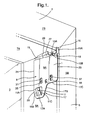
- bracket 1 in relation to a partial shown perspective view of a window 3 lined with a right vertical frame member 5 and a horizontal top frame member 7. As shown in Figure 1 the bracket 1 is mounted in a typical "in-recess" - position onto the lateral vertical surface 5A of the right vertical window frame member 5. The lateral vertical surface 5A is perpendicular to the vertical plane of the window 3.
- the bracket is relatively flat and it features a base 9, a tab 11 projecting from said base, a stopper 13 and a positioning flange 15 both formed on the base 9 and diagonally removed from the tab 11.
- the bracket base 9 has a base lateral front 9A for engagement to an end portion of a head rail of a blind and a base lateral back 9B for contacting the vertical lateral surface 5A.
- the base 9 further has a base lower side 17, a base top side 19 and base inner and base outer sides 21, 23,the inner side being adjacent the window 3 and the outer side is further removed from the window 3.
- the base lower side 17 is generally S-shaped and includes a horizontal lower base leg 17A generally parallel to the base top side 19, a generally vertical intermediate leg 17B generally parallel to the inner and outer base sides 21, 23 and an upper horizontal leg 17C also parallel to the base top side 19.
- the tab 11 projects at an acute angle from a tab-area 25 defined in the base lateral front 9A of base 9 by the lower leg 17A and base inner side 21 and intermediate leg 17B of base lower side 17.
- the tab 11 is generally rectangular and projects at an acute angle laterally out from lateral front 9A of the base.
- the tab 11 includes a top edge 11A which is in a plane generally parallel to the base top side 19 but laterally removed therefrom.
- the tab 11 further has a pair of inner and outer sides 11 B, 11 C, perpendicular to the top edge 11 A.
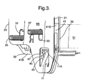
- the tab 11 is resilient and thus can be laterally pushed back towards the lateral front 9A of the bracket base and thus towards surface 5A of the vertical frame member 5. Tab 11 can also resiliently flex back out again to its acute angle. This feature is necessary for mounting a blind assembly to the bracket 1 and is explained in relation to Figures 2 and 3 .
- the bracket 1 further has, at its top side 19, a horizontal top flange 27 which projects perpendicular and laterally away from the base 9, in a plane parallel to the lateral horizontal surface 7A of the horizontal top frame member 7 of the window 3.
- the stopper 13 is formed on the horizontal bracket top flange 27 and adjacent the outer bracket side 23.
- the stopper 13 includes a stopper base 13A projecting from the horizontal top flange 27 and in the same the lateral horizontal plane as flange 27, and a stopper body 13B which is vertically depending from the stopper base and is perpendicular to base 9 and thus when the bracket is mounted to the frame in the same plane as the window 3 and the vertical outer surface 5B of the right vertical frame member 5.
- the stopper body 13B is preferably a rectangular body.
- the stopper body 13B will co-operate with a portion of the blind assembly, once it is attached to the bracket 1 and prevents rotation thereof relative to the tab 11. This feature is explained in relation to Figures 2 and 4 .
- the positioning flange 15 of the bracket projects vertically up from the bracket top flange 27.
- the positioning flange 15 is, just as the stopper flange 13, perpendicular to base 9 and thus when the bracket is mounted to the frame in the same plane as the window 3 and the vertical outer surface 5B of the right vertical frame member 5 and adjacent the brackets outer side 23.
- the stopper flange 13 and the positioning flange 15 are in parallel spaced apart planes.
- the positioning flange 15 is generally rectangular and it has an outer surface 15A and an inner surface 15B.
- the inner surface 15B of the positioning flange 15 is for contacting the outer surface 7B of the horizontal frame member 7, in order to position the bracket on the lateral vertical surface 5A relative to the window 3 and the front plane of the window frame.
- auxiliary positioning flange 29 for use in roof windows.
- the auxiliary positioning flange 29 comprises a top section 29A at a first oblique angle and section 29B at a second oblique angle.
- the auxiliary positioning flange 29 abuts against the inner surface 7B of the horizontal frame member 7 with one of the two top sections 29A, 29B depending on the actual angle of the inner surface 7B.
- the bracket can thus be perfectly aligned in the corner of the joining frames, and be at the correct orientation relative thereto with respect to the oblique angle relative to the plane of the window 3 without difficulty.
- the auxiliary positioning flange 29 projects vertically up from the bracket top flange 27 in a plane parallel to the bracket base 9 and once installed also parallel to the lateral vertical surface 5A of the frame member.
- a pair of parallel oblong through holes 31, 33 are shown with suitable fasteners 35,37 for attachment of the bracket to the lateral vertical surface 5A of the window frame. Between the two holes 31, 33 is a mark, here the letter R, indicating at what vertical frame member the bracket is to be attached. R stands for 'right vertical frame member'.
- Figure 2 shows the bracket 1 with attached thereto an end cap 39 of a blind housing 51 for a roller blind, in a position as if looking through the right vertical frame member 5 from the lateral vertical surface 5A to the base rear 9B.
- the blind housing 51 includes an elongated rounded profile with an elongated horizontally extending top portion 51A, which once the blind is installed in the window abuts the vertical outer surface 7B of the horizontal frame member 7.
- the end cap 39 includes an end cap base 41 having a front surface 41A facing into the blind housing and a rear surface 41 B facing the front bracket base 9A when mounted thereto.
- the end cap further has a top side 41C, a bottom side 41 D, an inner 41 E and outer side 41 F.
- the inner side 41 E of the end cap 39 is co-planar with the inner side of the bracket.
- a recessed area 43 in its base rear 41 B is in a plane coinciding with and facing the tab area 25 of bracket 1.
- the recessed area 43 as best seen in Figure 3 , includes a recess 45 in which tab 11 can be accommodated and a lateral horizontal top surface 47 which can rest on the tab top rim 11A of the bracket.
- the end cap further includes a vertical cover flange 49 perpendicular to its base and at the outer side 41 F.
- the vertical cover flange 49 is destined to abut the outer vertical surface 5B of the right vertical frame member 5 and the outer horizontal surface 7B of the horizontal frame member 7 once the blind is installed to the window frame.
- the portion abutting the right vertical frame member 5 closes any gap between blind, bracket and right vertical frame member, and the portion abutting the horizontal frame member 7B also covers the positioning flange 15.
- Figure 2 also shows the stopper base 13A and the positioning flange 15 in relation to the end cap 39.
- the inner surface 15B of positioning flange 15 is seen clearly, while the outer face 15A is covered by a vertical cover flange 49 of the end cap 39.
- the vertical cover flange 49 of the end cap 39 also partially covers an end portion of the top edge 51A of the blind housing 51.
- the weight of the blind rests on the tab top edge 11A by means of the lateral horizontal top rim 47 in recess 45 in the end cap. Since the tab 11 and recess 45 are not in line with a vertical centre line of the blind, there is a risk of the blind rotating relative to the tab.
- the stopper body 13B acts on the blind end cap 39 diagonally removed from the tab 11 and as such prevents rotation of the blind relative to the tab 11, this is best seen in Figure 4 .
- Figure 4 provides a view from the blind towards the base front 9A.
- the end cap 39 is carried by the bracket 1 at the front side 9A, and is thus perfectly aligned thereto.
- Stopper body 13B falls into a gap 53 on the end cap, adjacent the inner surface of the vertical cover flange 49 of thereof.
- the stopper gap 53 is formed between a pair of opposite outer and inner gap members 55, 57 parallel to the vertical cover flange 49.
- the gap members 55,57 thus define a pair of opposite inner and outer vertical surfaces on the end cap 39, accommodating the stopper body 13B of the bracket between them.
- the vertical outer gap member 55 is on the inner surface of the vertical cover flange 49 and the vertical inner gap member 57 is spaced apart and on a top portion of the end cap 39.
- the stopper gap 53 is in the same plane as the stopper body 13B. Stopper body 13B by its inner surface 13B' acting on the outer vertical surface 59 of the inner gap member 57.
- Figure 5 shows a second embodiment of the bracket 101 of the invention, this embodiment is similar to that of figures 1-4 and for the description of which corresponding reference numerals (greater by 100) are used below for describing the same parts or corresponding parts.
- Bracket 101 is shown mounted to a post 161 which projects from the vertical lateral surface 105A of the right vertical frame member 105.
- a post 161 can be already present on the window frame because of previous use for mounting different window blinds, i.e. such as a curtain or the like. Or for mounting blinds of a different brand.
- the bracket 101 is provided with a through opening 163 to accommodate the post 161 and use it as a means for attaching the bracket to the frame member 105. Thus other fasteners and the screw holes 31, 31 of the first embodiment are no longer necessary.
- the through opening 163 can be provided with one or more lateral extending centering flanges 165.
- Such resilient centering tabs 165 can be easily formed on the circumferential surface of the through opening 163.
- the advantage of this solution is that any posts already present on the window frame do not have to be removed. Instead, they can be used as means for attaching the bracket to the window frame.
- bracket of Figure 5 could be provided in a bracket in conjunction with different means for carrying a blind than the tab and/or with different means for preventing rotation than the stopper flange.
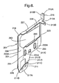
- Figure 6 shows a third embodiment of the bracket 201 of the invention, this embodiment is similar to that of figures 5 and for the description of which corresponding reference numerals (greater by 100) are used below for describing the same parts or corresponding parts.
- bracket 201 is shown in a shown perspective view, the bracket is relatively flat and it features a base 209, a tab 211 projecting from said base, a stopper 213 and a positioning flange 215 both formed on the base 209 and diagonally removed from the tab 211.
- the base 209 is of the same shape as the bracket of Figure 1 , thus has a base top side 219 and base inner and base outer sides 221, 223, a base lower side 217 which is generally S-shaped and includes a horizontal lower base leg 217A generally parallel to the base top side 219, a generally vertical intermediate leg 217B generally parallel to the inner and outer base sides 221, 223 and an upper horizontal leg 217C also parallel to the base top side 219.
- the tab 211 projects at an acute angle from the tab-area 225 and includes a top edge 211A which is in a plane generally parallel to the base top side 219 but laterally removed therefrom.
- the tab 211 further has a pair of inner and outer sides 211 B, 211C, perpendicular to the top edge 211A.
- the horizontal top flange 227 projects perpendicular and laterally away from the base 209, and stopper 213 is formed it and adjacent the outer bracket side 223
- the stopper 213 includes a stopper base 213A projecting from the horizontal top flange 227 and in the same the lateral horizontal plane as flange 227, and a stopper body 213B which is vertically depending from the stopper base.
- the positioning flange 215 of the bracket projects vertically up from the bracket top flange 227, is generally rectangular and it has an outer surface 215A and an inner surface 215B.
- the auxiliary positioning flange 229 projects vertically up from the bracket top flange 227 in a plane perpendicular to the positioning flange 215, and generally parallel to the tab 211.
- a pair of parallel oblong through holes 231, 233 are shown with a marking R between them, indicating the bracket is to be attached to the right vertical frame member of a window frame.
- Bracket 201 is shown having both a through opening 263 to accommodate a post 261 and use it as a means for attaching the bracket to the frame member 105 as well as the screw holes 231, 233 which can be used to fix the bracket to a window frame member.
- the screw holes 231, 233 only are necessary when no post is present in the window frame and thus are closed by break-out tabs 231 A, 233B.
- the break-out tabs 231A, 233A can be removed when the blind installer sees that no post is present in the window frame.
- the bracket of the invention is preferably a sheet metal bracket.
- bracket is described in relation to frame members 5 and 7 surrounding window 3, it can also be used when no frame members are present and only horizontal and vertical lateral fixed surfaces 7A, 5A and horizontal and vertical front surfaces 7B and 5B are present.
- the bracket is shown to have an S-shaped lower side 17; instead, the bracket can be generally rectangular and the lower side 17 be straight.
- the positioning flange 15 is shown projecting from top flange 27; instead, it can also project from outer side 23, and be parallel to outer vertical surface 5B of vertical member 5.
- the bracket of the invention is shown to carry an end cap 39 for a roller blind housing 41, but it can also be used to carry a Venetian blind or any other blind as long as the end cap of such blinds is provided with recessed area having the lateral horizontal rim to rest atop the tab top edge.
Landscapes
- Engineering & Computer Science (AREA)
- Structural Engineering (AREA)
- Architecture (AREA)
- Civil Engineering (AREA)
- Blinds (AREA)
- Roof Covering Using Slabs Or Stiff Sheets (AREA)
Priority Applications (1)
| Application Number | Priority Date | Filing Date | Title |
|---|---|---|---|
| EP08252095.8A EP2011951B1 (fr) | 2007-07-03 | 2008-06-18 | Support avec un dispositif de couverture |
Applications Claiming Priority (2)
| Application Number | Priority Date | Filing Date | Title |
|---|---|---|---|
| EP07012963 | 2007-07-03 | ||
| EP08252095.8A EP2011951B1 (fr) | 2007-07-03 | 2008-06-18 | Support avec un dispositif de couverture |
Publications (3)
| Publication Number | Publication Date |
|---|---|
| EP2011951A2 true EP2011951A2 (fr) | 2009-01-07 |
| EP2011951A3 EP2011951A3 (fr) | 2011-06-15 |
| EP2011951B1 EP2011951B1 (fr) | 2019-09-25 |
Family
ID=39765325
Family Applications (1)
| Application Number | Title | Priority Date | Filing Date |
|---|---|---|---|
| EP08252095.8A Active EP2011951B1 (fr) | 2007-07-03 | 2008-06-18 | Support avec un dispositif de couverture |
Country Status (2)
| Country | Link |
|---|---|
| EP (1) | EP2011951B1 (fr) |
| DK (1) | DK2011951T3 (fr) |
Cited By (1)
| Publication number | Priority date | Publication date | Assignee | Title |
|---|---|---|---|---|
| DE102016122915A1 (de) * | 2016-11-28 | 2018-05-30 | Hunter Douglas Industries Switzerland Gmbh | Haltevorrichtung zum Halten einer Sonnenschutzvorrichtung und Haltesystem |
Citations (6)
| Publication number | Priority date | Publication date | Assignee | Title |
|---|---|---|---|---|
| US1992148A (en) | 1934-05-18 | 1935-02-19 | United Metal Box Co Inc | Venetian blind bracket |
| US2027280A (en) | 1934-10-12 | 1936-01-07 | Carl Lindemann Company Inc | Venetian blind bracket |
| DE3048333A1 (de) | 1980-12-20 | 1982-07-01 | Velora Wohn-Dekor GmbH, 2000 Hamburg | "kombinierte rollostangen- und jalousiestangen-halterung" |
| DE3330472A1 (de) | 1983-08-24 | 1985-03-07 | Hüppe GmbH, 2900 Oldenburg | Halterungsvorrichtung fuer ein insbesondere fuer dachflaechenfenster bestimmtes springrollo |
| EP1003953A1 (fr) | 1997-08-12 | 2000-05-31 | VELUX Industri A/S | Organes de support pour dispositif ecran |
| EP1151176A1 (fr) | 1999-02-12 | 2001-11-07 | VKR Holding A/S | Moyen de support pour dispositif de fermeture |
Family Cites Families (3)
| Publication number | Priority date | Publication date | Assignee | Title |
|---|---|---|---|---|
| US1744682A (en) * | 1928-03-22 | 1930-01-21 | Springless Shade Company | Shade bracket |
| US2552180A (en) * | 1948-01-26 | 1951-05-08 | Kenney Mfg Co | Curtain rod bracket |
| DE4107086A1 (de) * | 1991-02-12 | 1992-08-13 | Helmut Schlotterbeck | Lager fuer eine drehende und wickelnde welle von rolladen, jalousien, markisen u. dgl. |
-
2008
- 2008-06-18 DK DK08252095T patent/DK2011951T3/da active
- 2008-06-18 EP EP08252095.8A patent/EP2011951B1/fr active Active
Patent Citations (6)
| Publication number | Priority date | Publication date | Assignee | Title |
|---|---|---|---|---|
| US1992148A (en) | 1934-05-18 | 1935-02-19 | United Metal Box Co Inc | Venetian blind bracket |
| US2027280A (en) | 1934-10-12 | 1936-01-07 | Carl Lindemann Company Inc | Venetian blind bracket |
| DE3048333A1 (de) | 1980-12-20 | 1982-07-01 | Velora Wohn-Dekor GmbH, 2000 Hamburg | "kombinierte rollostangen- und jalousiestangen-halterung" |
| DE3330472A1 (de) | 1983-08-24 | 1985-03-07 | Hüppe GmbH, 2900 Oldenburg | Halterungsvorrichtung fuer ein insbesondere fuer dachflaechenfenster bestimmtes springrollo |
| EP1003953A1 (fr) | 1997-08-12 | 2000-05-31 | VELUX Industri A/S | Organes de support pour dispositif ecran |
| EP1151176A1 (fr) | 1999-02-12 | 2001-11-07 | VKR Holding A/S | Moyen de support pour dispositif de fermeture |
Cited By (1)
| Publication number | Priority date | Publication date | Assignee | Title |
|---|---|---|---|---|
| DE102016122915A1 (de) * | 2016-11-28 | 2018-05-30 | Hunter Douglas Industries Switzerland Gmbh | Haltevorrichtung zum Halten einer Sonnenschutzvorrichtung und Haltesystem |
Also Published As
| Publication number | Publication date |
|---|---|
| EP2011951A3 (fr) | 2011-06-15 |
| EP2011951B1 (fr) | 2019-09-25 |
| DK2011951T3 (da) | 2019-12-09 |
Similar Documents
| Publication | Publication Date | Title |
|---|---|---|
| UA67808C2 (uk) | Опорний засіб для екрануючого пристрою | |
| US5667178A (en) | Bracket assembly for mounting a shade | |
| EP3995664B1 (fr) | Assemblage d'un dispositif d'écran et d'un profil de fixation pour fixer un caisson d'écran de ce dispositif d'écran | |
| EP2238309A1 (fr) | Système d'écran avec un support pour le montage d'un rail de guidage | |
| US10526842B2 (en) | Mounting arrangement | |
| JP5638478B2 (ja) | 下枠および建具 | |
| KR102666482B1 (ko) | 유리난간 조립체 | |
| EP2011951A2 (fr) | Support pour un dispositif de couverture | |
| US20040221970A1 (en) | Window covering headrail having ornamental panel | |
| JP6937565B2 (ja) | 改装サッシ及び改装サッシの施工方法 | |
| EP1377713B1 (fr) | Cadre de parement de facade | |
| BE1029888B1 (nl) | Schermprofielsamenstel | |
| EP1069272A1 (fr) | Profilé divisible en aluminium pour la fabrication de vantaux de portes ou de fenêtres | |
| CN218581432U (zh) | 一种幕墙开启窗的窗框安装结构 | |
| JP2012026100A (ja) | シャッターケース連結カバーの取付構造 | |
| JP6127110B2 (ja) | レール部材の改修方法 | |
| KR102934476B1 (ko) | 유리난간 조립체 | |
| JPH0616035Y2 (ja) | スチール窓枠における額縁の取付構造 | |
| JP7815016B2 (ja) | シャッター装置及びシャッター装置の施工方法 | |
| JP7710959B2 (ja) | シャッターにおける引っ掛け金具の固定構造 | |
| JP6816966B2 (ja) | 庇を備えたシャッターケース及び当該シャッターケースを備えたシャッター装置 | |
| EP1988251A2 (fr) | Pattes de fixation de store et outils, composants et procédé correspondants | |
| KR100683903B1 (ko) | 빌딩용 차광 장치 | |
| EP4119762A1 (fr) | Assemblage d'un dispositif d'écran et moyens de fixation destinés à la fixation d'un boîtier d'écran dudit dispositif d'écran | |
| CA2759977A1 (fr) | Alarme de fenetre a guillotine |
Legal Events
| Date | Code | Title | Description |
|---|---|---|---|
| PUAI | Public reference made under article 153(3) epc to a published international application that has entered the european phase |
Free format text: ORIGINAL CODE: 0009012 |
|
| AK | Designated contracting states |
Kind code of ref document: A2 Designated state(s): AT BE BG CH CY CZ DE DK EE ES FI FR GB GR HR HU IE IS IT LI LT LU LV MC MT NL NO PL PT RO SE SI SK TR |
|
| AX | Request for extension of the european patent |
Extension state: AL BA MK RS |
|
| PUAL | Search report despatched |
Free format text: ORIGINAL CODE: 0009013 |
|
| AK | Designated contracting states |
Kind code of ref document: A3 Designated state(s): AT BE BG CH CY CZ DE DK EE ES FI FR GB GR HR HU IE IS IT LI LT LU LV MC MT NL NO PL PT RO SE SI SK TR |
|
| AX | Request for extension of the european patent |
Extension state: AL BA MK RS |
|
| 17P | Request for examination filed |
Effective date: 20111215 |
|
| AKX | Designation fees paid |
Designated state(s): AT BE BG CH CY LI |
|
| REG | Reference to a national code |
Ref country code: DE Ref legal event code: R108 Effective date: 20120222 |
|
| RBV | Designated contracting states (corrected) |
Designated state(s): AT BE BG CH CY CZ DE DK EE ES FI FR GB GR HR HU IE IS IT LI LT LU LV MC MT NL NO PL PT RO SE SI SK TR |
|
| 17Q | First examination report despatched |
Effective date: 20131121 |
|
| STAA | Information on the status of an ep patent application or granted ep patent |
Free format text: STATUS: EXAMINATION IS IN PROGRESS |
|
| GRAP | Despatch of communication of intention to grant a patent |
Free format text: ORIGINAL CODE: EPIDOSNIGR1 |
|
| STAA | Information on the status of an ep patent application or granted ep patent |
Free format text: STATUS: GRANT OF PATENT IS INTENDED |
|
| INTG | Intention to grant announced |
Effective date: 20170601 |
|
| GRAJ | Information related to disapproval of communication of intention to grant by the applicant or resumption of examination proceedings by the epo deleted |
Free format text: ORIGINAL CODE: EPIDOSDIGR1 |
|
| STAA | Information on the status of an ep patent application or granted ep patent |
Free format text: STATUS: EXAMINATION IS IN PROGRESS |
|
| INTC | Intention to grant announced (deleted) | ||
| GRAP | Despatch of communication of intention to grant a patent |
Free format text: ORIGINAL CODE: EPIDOSNIGR1 |
|
| STAA | Information on the status of an ep patent application or granted ep patent |
Free format text: STATUS: GRANT OF PATENT IS INTENDED |
|
| INTG | Intention to grant announced |
Effective date: 20190405 |
|
| GRAS | Grant fee paid |
Free format text: ORIGINAL CODE: EPIDOSNIGR3 |
|
| GRAA | (expected) grant |
Free format text: ORIGINAL CODE: 0009210 |
|
| STAA | Information on the status of an ep patent application or granted ep patent |
Free format text: STATUS: THE PATENT HAS BEEN GRANTED |
|
| AK | Designated contracting states |
Kind code of ref document: B1 Designated state(s): AT BE BG CH CY CZ DE DK EE ES FI FR GB GR HR HU IE IS IT LI LT LU LV MC MT NL NO PL PT RO SE SI SK TR |
|
| REG | Reference to a national code |
Ref country code: GB Ref legal event code: FG4D |
|
| REG | Reference to a national code |
Ref country code: CH Ref legal event code: EP |
|
| REG | Reference to a national code |
Ref country code: AT Ref legal event code: REF Ref document number: 1183988 Country of ref document: AT Kind code of ref document: T Effective date: 20191015 |
|
| REG | Reference to a national code |
Ref country code: IE Ref legal event code: FG4D |
|
| REG | Reference to a national code |
Ref country code: DE Ref legal event code: R096 Ref document number: 602008061270 Country of ref document: DE |
|
| REG | Reference to a national code |
Ref country code: SE Ref legal event code: TRGR |
|
| REG | Reference to a national code |
Ref country code: NL Ref legal event code: FP |
|
| REG | Reference to a national code |
Ref country code: DK Ref legal event code: T3 Effective date: 20191203 |
|
| PG25 | Lapsed in a contracting state [announced via postgrant information from national office to epo] |
Ref country code: LT Free format text: LAPSE BECAUSE OF FAILURE TO SUBMIT A TRANSLATION OF THE DESCRIPTION OR TO PAY THE FEE WITHIN THE PRESCRIBED TIME-LIMIT Effective date: 20190925 Ref country code: HR Free format text: LAPSE BECAUSE OF FAILURE TO SUBMIT A TRANSLATION OF THE DESCRIPTION OR TO PAY THE FEE WITHIN THE PRESCRIBED TIME-LIMIT Effective date: 20190925 Ref country code: BG Free format text: LAPSE BECAUSE OF FAILURE TO SUBMIT A TRANSLATION OF THE DESCRIPTION OR TO PAY THE FEE WITHIN THE PRESCRIBED TIME-LIMIT Effective date: 20191225 Ref country code: FI Free format text: LAPSE BECAUSE OF FAILURE TO SUBMIT A TRANSLATION OF THE DESCRIPTION OR TO PAY THE FEE WITHIN THE PRESCRIBED TIME-LIMIT Effective date: 20190925 |
|
| REG | Reference to a national code |
Ref country code: NO Ref legal event code: T2 Effective date: 20190925 |
|
| REG | Reference to a national code |
Ref country code: LT Ref legal event code: MG4D |
|
| PG25 | Lapsed in a contracting state [announced via postgrant information from national office to epo] |
Ref country code: GR Free format text: LAPSE BECAUSE OF FAILURE TO SUBMIT A TRANSLATION OF THE DESCRIPTION OR TO PAY THE FEE WITHIN THE PRESCRIBED TIME-LIMIT Effective date: 20191226 Ref country code: LV Free format text: LAPSE BECAUSE OF FAILURE TO SUBMIT A TRANSLATION OF THE DESCRIPTION OR TO PAY THE FEE WITHIN THE PRESCRIBED TIME-LIMIT Effective date: 20190925 |
|
| REG | Reference to a national code |
Ref country code: AT Ref legal event code: MK05 Ref document number: 1183988 Country of ref document: AT Kind code of ref document: T Effective date: 20190925 |
|
| PG25 | Lapsed in a contracting state [announced via postgrant information from national office to epo] |
Ref country code: RO Free format text: LAPSE BECAUSE OF FAILURE TO SUBMIT A TRANSLATION OF THE DESCRIPTION OR TO PAY THE FEE WITHIN THE PRESCRIBED TIME-LIMIT Effective date: 20190925 Ref country code: EE Free format text: LAPSE BECAUSE OF FAILURE TO SUBMIT A TRANSLATION OF THE DESCRIPTION OR TO PAY THE FEE WITHIN THE PRESCRIBED TIME-LIMIT Effective date: 20190925 Ref country code: IT Free format text: LAPSE BECAUSE OF FAILURE TO SUBMIT A TRANSLATION OF THE DESCRIPTION OR TO PAY THE FEE WITHIN THE PRESCRIBED TIME-LIMIT Effective date: 20190925 Ref country code: AT Free format text: LAPSE BECAUSE OF FAILURE TO SUBMIT A TRANSLATION OF THE DESCRIPTION OR TO PAY THE FEE WITHIN THE PRESCRIBED TIME-LIMIT Effective date: 20190925 Ref country code: ES Free format text: LAPSE BECAUSE OF FAILURE TO SUBMIT A TRANSLATION OF THE DESCRIPTION OR TO PAY THE FEE WITHIN THE PRESCRIBED TIME-LIMIT Effective date: 20190925 Ref country code: PL Free format text: LAPSE BECAUSE OF FAILURE TO SUBMIT A TRANSLATION OF THE DESCRIPTION OR TO PAY THE FEE WITHIN THE PRESCRIBED TIME-LIMIT Effective date: 20190925 Ref country code: PT Free format text: LAPSE BECAUSE OF FAILURE TO SUBMIT A TRANSLATION OF THE DESCRIPTION OR TO PAY THE FEE WITHIN THE PRESCRIBED TIME-LIMIT Effective date: 20200127 |
|
| PG25 | Lapsed in a contracting state [announced via postgrant information from national office to epo] |
Ref country code: CZ Free format text: LAPSE BECAUSE OF FAILURE TO SUBMIT A TRANSLATION OF THE DESCRIPTION OR TO PAY THE FEE WITHIN THE PRESCRIBED TIME-LIMIT Effective date: 20190925 Ref country code: IS Free format text: LAPSE BECAUSE OF FAILURE TO SUBMIT A TRANSLATION OF THE DESCRIPTION OR TO PAY THE FEE WITHIN THE PRESCRIBED TIME-LIMIT Effective date: 20200224 Ref country code: SK Free format text: LAPSE BECAUSE OF FAILURE TO SUBMIT A TRANSLATION OF THE DESCRIPTION OR TO PAY THE FEE WITHIN THE PRESCRIBED TIME-LIMIT Effective date: 20190925 |
|
| REG | Reference to a national code |
Ref country code: DE Ref legal event code: R097 Ref document number: 602008061270 Country of ref document: DE |
|
| PG2D | Information on lapse in contracting state deleted |
Ref country code: IS |
|
| PG25 | Lapsed in a contracting state [announced via postgrant information from national office to epo] |
Ref country code: IS Free format text: LAPSE BECAUSE OF FAILURE TO SUBMIT A TRANSLATION OF THE DESCRIPTION OR TO PAY THE FEE WITHIN THE PRESCRIBED TIME-LIMIT Effective date: 20200126 |
|
| PLBE | No opposition filed within time limit |
Free format text: ORIGINAL CODE: 0009261 |
|
| STAA | Information on the status of an ep patent application or granted ep patent |
Free format text: STATUS: NO OPPOSITION FILED WITHIN TIME LIMIT |
|
| 26N | No opposition filed |
Effective date: 20200626 |
|
| PG25 | Lapsed in a contracting state [announced via postgrant information from national office to epo] |
Ref country code: SI Free format text: LAPSE BECAUSE OF FAILURE TO SUBMIT A TRANSLATION OF THE DESCRIPTION OR TO PAY THE FEE WITHIN THE PRESCRIBED TIME-LIMIT Effective date: 20190925 |
|
| PG25 | Lapsed in a contracting state [announced via postgrant information from national office to epo] |
Ref country code: MC Free format text: LAPSE BECAUSE OF FAILURE TO SUBMIT A TRANSLATION OF THE DESCRIPTION OR TO PAY THE FEE WITHIN THE PRESCRIBED TIME-LIMIT Effective date: 20190925 |
|
| REG | Reference to a national code |
Ref country code: CH Ref legal event code: PL |
|
| PG25 | Lapsed in a contracting state [announced via postgrant information from national office to epo] |
Ref country code: LU Free format text: LAPSE BECAUSE OF NON-PAYMENT OF DUE FEES Effective date: 20200618 |
|
| PG25 | Lapsed in a contracting state [announced via postgrant information from national office to epo] |
Ref country code: CH Free format text: LAPSE BECAUSE OF NON-PAYMENT OF DUE FEES Effective date: 20200630 Ref country code: LI Free format text: LAPSE BECAUSE OF NON-PAYMENT OF DUE FEES Effective date: 20200630 Ref country code: IE Free format text: LAPSE BECAUSE OF NON-PAYMENT OF DUE FEES Effective date: 20200618 |
|
| PG25 | Lapsed in a contracting state [announced via postgrant information from national office to epo] |
Ref country code: TR Free format text: LAPSE BECAUSE OF FAILURE TO SUBMIT A TRANSLATION OF THE DESCRIPTION OR TO PAY THE FEE WITHIN THE PRESCRIBED TIME-LIMIT Effective date: 20190925 Ref country code: MT Free format text: LAPSE BECAUSE OF FAILURE TO SUBMIT A TRANSLATION OF THE DESCRIPTION OR TO PAY THE FEE WITHIN THE PRESCRIBED TIME-LIMIT Effective date: 20190925 Ref country code: CY Free format text: LAPSE BECAUSE OF FAILURE TO SUBMIT A TRANSLATION OF THE DESCRIPTION OR TO PAY THE FEE WITHIN THE PRESCRIBED TIME-LIMIT Effective date: 20190925 |
|
| P01 | Opt-out of the competence of the unified patent court (upc) registered |
Effective date: 20230331 |
|
| PGFP | Annual fee paid to national office [announced via postgrant information from national office to epo] |
Ref country code: NL Payment date: 20240426 Year of fee payment: 17 |
|
| PGFP | Annual fee paid to national office [announced via postgrant information from national office to epo] |
Ref country code: GB Payment date: 20240425 Year of fee payment: 17 |
|
| PGFP | Annual fee paid to national office [announced via postgrant information from national office to epo] |
Ref country code: DE Payment date: 20240423 Year of fee payment: 17 |
|
| PGFP | Annual fee paid to national office [announced via postgrant information from national office to epo] |
Ref country code: DK Payment date: 20240612 Year of fee payment: 17 |
|
| PGFP | Annual fee paid to national office [announced via postgrant information from national office to epo] |
Ref country code: NO Payment date: 20240611 Year of fee payment: 17 Ref country code: FR Payment date: 20240422 Year of fee payment: 17 |
|
| PGFP | Annual fee paid to national office [announced via postgrant information from national office to epo] |
Ref country code: SE Payment date: 20240429 Year of fee payment: 17 Ref country code: BE Payment date: 20240515 Year of fee payment: 17 |
|
| REG | Reference to a national code |
Ref country code: DE Ref legal event code: R119 Ref document number: 602008061270 Country of ref document: DE |
|
| REG | Reference to a national code |
Ref country code: DK Ref legal event code: EBP Effective date: 20250630 |
|
| REG | Reference to a national code |
Ref country code: SE Ref legal event code: EUG |
|
| REG | Reference to a national code |
Ref country code: NL Ref legal event code: MM Effective date: 20250701 |
|
| GBPC | Gb: european patent ceased through non-payment of renewal fee |
Effective date: 20250618 |
|
| REG | Reference to a national code |
Ref country code: BE Ref legal event code: MM Effective date: 20250630 |
|
| PG25 | Lapsed in a contracting state [announced via postgrant information from national office to epo] |
Ref country code: NL Free format text: LAPSE BECAUSE OF NON-PAYMENT OF DUE FEES Effective date: 20250701 |
|
| PG25 | Lapsed in a contracting state [announced via postgrant information from national office to epo] |
Ref country code: GB Free format text: LAPSE BECAUSE OF NON-PAYMENT OF DUE FEES Effective date: 20250618 |
|
| PG25 | Lapsed in a contracting state [announced via postgrant information from national office to epo] |
Ref country code: NO Free format text: LAPSE BECAUSE OF NON-PAYMENT OF DUE FEES Effective date: 20250630 Ref country code: DE Free format text: LAPSE BECAUSE OF NON-PAYMENT OF DUE FEES Effective date: 20260101 |
|
| PG25 | Lapsed in a contracting state [announced via postgrant information from national office to epo] |
Ref country code: BE Free format text: LAPSE BECAUSE OF NON-PAYMENT OF DUE FEES Effective date: 20250630 |
|
| PG25 | Lapsed in a contracting state [announced via postgrant information from national office to epo] |
Ref country code: FR Free format text: LAPSE BECAUSE OF NON-PAYMENT OF DUE FEES Effective date: 20250630 |