EP2011952A2 - Espaceur pour un chariot d'une installation d'obscurcissement et installation d'obscurcissement - Google Patents
Espaceur pour un chariot d'une installation d'obscurcissement et installation d'obscurcissement Download PDFInfo
- Publication number
- EP2011952A2 EP2011952A2 EP08104616A EP08104616A EP2011952A2 EP 2011952 A2 EP2011952 A2 EP 2011952A2 EP 08104616 A EP08104616 A EP 08104616A EP 08104616 A EP08104616 A EP 08104616A EP 2011952 A2 EP2011952 A2 EP 2011952A2
- Authority
- EP
- European Patent Office
- Prior art keywords
- carriage
- spacer
- coupling piece
- ramp
- hook
- Prior art date
- Legal status (The legal status is an assumption and is not a legal conclusion. Google has not performed a legal analysis and makes no representation as to the accuracy of the status listed.)
- Withdrawn
Links
- 125000006850 spacer group Chemical group 0.000 claims abstract description 63
- 230000008878 coupling Effects 0.000 claims abstract description 25
- 238000010168 coupling process Methods 0.000 claims abstract description 25
- 238000005859 coupling reaction Methods 0.000 claims abstract description 25
- 238000000034 method Methods 0.000 claims description 8
- 230000000630 rising effect Effects 0.000 claims description 4
- 238000009434 installation Methods 0.000 claims 6
- 210000002445 nipple Anatomy 0.000 description 5
- 230000004323 axial length Effects 0.000 description 2
- 238000005452 bending Methods 0.000 description 2
- 238000004140 cleaning Methods 0.000 description 2
- 230000008719 thickening Effects 0.000 description 2
- 230000005540 biological transmission Effects 0.000 description 1
- 230000000295 complement effect Effects 0.000 description 1
- 230000000994 depressogenic effect Effects 0.000 description 1
- 230000018109 developmental process Effects 0.000 description 1
- 238000006073 displacement reaction Methods 0.000 description 1
- 238000005553 drilling Methods 0.000 description 1
Images


Classifications
-
- E—FIXED CONSTRUCTIONS
- E06—DOORS, WINDOWS, SHUTTERS, OR ROLLER BLINDS IN GENERAL; LADDERS
- E06B—FIXED OR MOVABLE CLOSURES FOR OPENINGS IN BUILDINGS, VEHICLES, FENCES OR LIKE ENCLOSURES IN GENERAL, e.g. DOORS, WINDOWS, BLINDS, GATES
- E06B9/00—Screening or protective devices for wall or similar openings, with or without operating or securing mechanisms; Closures of similar construction
- E06B9/24—Screens or other constructions affording protection against light, especially against sunshine; Similar screens for privacy or appearance; Slat blinds
- E06B9/26—Lamellar or like blinds, e.g. venetian blinds
- E06B9/36—Lamellar or like blinds, e.g. venetian blinds with vertical lamellae ; Supporting rails therefor
- E06B9/362—Travellers; Lamellae suspension stems
- E06B9/365—Distance pieces therefor
Definitions
- the invention relates to a spacer for a carriage of a shading system, in particular vertical blind, with a coupling piece for detachable coupling with the carriage. Furthermore, the invention relates to a shading system, in particular vertical blinds, with carriages movably guided in a mounting rail, of which the carriage closest to one end of the mounting rail - end carriage - is held by means of a spacer to a predetermined position.
- Such a spacer or such shading system is from the EP 1 111 184 B1 known.
- the invention is primarily concerned with vertical blinds, but is analogous to other shading systems, such as horizontal blinds, in which the shading curtain is held on movably guided in a support rail carriage used.
- the mounting rail is mounted horizontally in the window reveal or on a building wall or ceiling.
- the actual curtain namely individual Vertical slats held on the support rail, wherein the curtain can be moved up and pulled in at transverse to the window plane oriented vertical slats by means of a at a foremost carriage, generally referred to as a train carriage attached cable.
- This train carriage successively draws on trailing carriages via spacers.
- a swivel gear is arranged in the carriage, which pivots about a pivot shaft, the vertical slats about its vertical longitudinal axis.
- vertical slats When tilted in a plane parallel to the window plane vertical slats should in particular arranged within a window reveal vertical blinds of the distance of one end of the support rail nearest carriage, generally referred to as Endwagen correspond to approximately half the slat width, so that the slat does not hit the inside against the window reveal.
- the invention is based on the problem of proposing a spacer and a shading system with such a spacer, which is as simple as possible in its structural design and yet a complete process of the disk set against the end of the support rail and a simple complete release of the end of the carriage allows.
- the spacer according to the invention is characterized in that the carriage is designed as a final carriage and cooperates with an actuating means which disengages the coupling piece in a process of the carriage in one direction and brings in process of the carriage in the opposite direction again ,
- the shading system is to solve this problem characterized in that the spacer has a cooperating with the end carriage actuator which brings the spacer in the process of the final carriage in a direction out of engagement and in the method of the end car in the opposite direction again engaged.
- the end car When the curtain is closed, the end car is held by the spacer at the predetermined position. Now, if the lamellae are moved together to form a package, the other carriage push the endcar towards the end of the mounting rail. In this case, the spacer is disengaged by the actuator and all carriages, including the end car, can be moved in the direction of the end of the support rail. In this case, the other carriages can be moved beyond the position defined by the spacer for the end car in itself position. Due to the actuator of the disengagement of the coupling piece and these are initially not held by the coupling piece in the process in the opposite direction. Only when the end car is held in its predetermined position when pulling the curtain, the coupling piece comes back into engagement with the end car and keeps it in the predetermined position.
- the coupling piece is designed as a hook.
- the hook itself prevents the carriage from being moved beyond the predetermined position in one direction and thus constitutes a stop for the carriage while the hook releases the carriage in the opposite direction.
- the spacer be formed so that this function can be disabled.
- a locking means on the spacer which completely locks the end carriage together with the hook.
- the hook thus forms a stop for the one direction of travel of the carriage (closing direction of the curtain), while the locking means is a stop in the opposite direction (opening direction of the curtain).
- the end car is firmly positioned between the hook and the locking means.
- this locking means is pivotally mounted on the spacer. By simply swiveling it can be put into or out of function.
- Fig. 1 shows a Laufzug, the sake of simplicity, here only four carriages 20, 21, 22 and 23 consists.
- This carriage 20..23 are movably guided in a support rail, not shown here in the longitudinal direction of the support rail.
- This support rail is closed by means of two end caps 24, 25 on the front side.
- left end cap 24 has only one deflection means for a circulating pull cord 26 and a pivot bearing for a turning shaft 27.
- the opposite end cap 25, which is also referred to in part as a functional cap, has deflection means for the pull cord 26, by means of which the pull cord 26 is guided out of the mounting rail down so that it can be detected by the operator.
- end cap 25 carries a circumferential chain 28, which cooperates with a pinion within the end cap 25 and by means of which the turning shaft 27 can be rotated about its longitudinal axis. This rotational movement is converted via known transmission within the carriage 20..23 in a pivoting movement of the hanging on the carriage 20..23 vertical slats.
- the in Fig. 1 the leftmost carriage 20 serves as a train carriage.
- a run 29 of the pull cord 26 is fixedly connected to the carriage 20, while the other strand 30 is slidably passed through the carriage 20.
- both strands 29, 30 slidably passed through all other carriages 21, 22, 23.
- By pulling the strand 29 of the carriage 20 is moved in the direction of the end cap 25 and thereby opened the curtain.
- the carriage 20 is moved in the direction of the other end cap 24, thereby closing the curtain.
- Distance strips 31 thereby pull the other carriages 21, 22, 23 in a conventional manner. In doing so, the in Fig.
- the spacer 32 is resiliently mounted on its associated end cap, here on the end cap 25.
- the spacer 32 is fixedly attached to the end cap 25, that by bending its end cap 25 facing the end 33, the resilient connection is made.
- the spacer 32 can thereby be pivoted in a plane parallel to the window plane or within the Behangbene.
- the end 33 opposite end of the spacer 32 has a coupling piece, namely a hook 34, on.
- the hook 34 the end car 23 can hook into the spacer 32, so that the end carriage 23 in the illustrations according to Fig. 11 to 13 not further to the right, so away from the associated end cap 25, can be moved.
- the end carriage 23 is held at a maximum distance to the end cap 25, which corresponds to half the slat width.
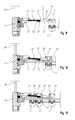
- the spacer 32 further comprises an upright web 35, which in the present case is arranged laterally on the spacer 32 (see, for example Fig. 2 and 5 ).
- This upright web 35 has, at its end facing the hook 34, a ramp 36 rising away from the hook 34.
- the length of this ramp 36 seen in the longitudinal direction of the spacer 32 and thus their slope is maximally as long as the width, also seen in the longitudinal direction of the spacer 32, the end car 23 and the other carriage 20, 21, 22. The reason for this from the following description even more apparent.
- the upright web 35 further has a second ramp 37 which drops evenly towards the end cap 25, said second ramp 37 engaging with the first, the hook 34 facing ramp 36 is flush, so that a common edge 38 is formed.
- a web 39 presses the hook 34 in the illustration according to FIG Fig. 11 to 13 down by sliding along the ramp 36.
- the hook 34 is disengaged from the end carriage 23 and also the following carriages 21, 22 can be pushed onto the spacer 32, without the hook 34 comes into engagement with these carriages 21, 22, so that all carriages 20..23 over the hook 34 can be pushed together to form a package.
- the webs 39 of all carriage 20..23 hold the spacer 32 namely by means of the gently sloping ramp 37 in the depressed down position, which actually corresponds to an upwardly pressed position.
- the axial length of the hook 34 facing the ramp 36 may not exceed the width of a carriage 20..23.
- the axial length of this ramp 36 may correspond to a maximum of the clearance between the two webs 39 one and the same carriage 20..23, as he otherwise when pulling the blind behind a freely movable carriage 20..22 and not only in the end car 23 would snap.
- the slope of this ramp 36 should be chosen so flat that as little force must be used to bring the hook 34 out of engagement. With these dimensions, so subsequent carriage 20..22 can postpone with the spacer 32.
- the following carriage 20..22 as in particular the example of the carriage 21 in Fig.
- the spacer 32 is associated with a locking means 40, which is designed so that it either the end car 23 completely blocked or in the sense of the basis of Fig. 11 to 13 function described.
- the latter position of the locking means 40 is in the Fig. 11 to 13 shown.
- the locking means 40 is pivotally supported on the spacer 32. It has for this purpose a nipple 41, which engages in a complementary bore 42 in the spacer 32 in the sense of a hinge connection.
- a nipple 41 which engages in a complementary bore 42 in the spacer 32 in the sense of a hinge connection.
- a kinematic reversal of the nipple 41 and the spacer 32 and the bore 42 are assigned to the locking means 40.
- the locking means 40 At its opposite end of the nipple 41, the locking means 40 an upright, directed away from the spacer 32 locking web 43, which at the in the Fig. 11 to 13 shown position, which is hereinafter referred to as rearwardly pivoted position, is arranged so that it does not hinder the displacement of the end car 23 within the predetermined range.
- This position of the locking means 40 is also in Fig. 10 shown.
- the locking means 40 to the nipple 41 by 180 ° in the in Fig. 8 swung position shown.
- Fig. 9 shows for clarity an intermediate position of the locking means 40.
- the end carriage 23 should be completely detachable from the spacer 32. This is done in a simple manner in that the spacer 32 by the operator, possibly with the aid of a suitable tool, is pivoted so that the hook 34 is disengaged from the web 39 of the endcar 23. Specifically, this is a thickening 45 provided laterally on the spacer 32. This thickening 45 is located in an area which is always freely accessible to the operator through the mounting rail. Aids are not required.
- the end car can now be moved away from the end cap 25 away.
- the disk pack can be moved freely on the mounting rail, so that the window can be cleaned in a comfortable way.
Landscapes
- Engineering & Computer Science (AREA)
- Structural Engineering (AREA)
- Architecture (AREA)
- Civil Engineering (AREA)
- Curtains And Furnishings For Windows Or Doors (AREA)
- Blinds (AREA)
Applications Claiming Priority (1)
| Application Number | Priority Date | Filing Date | Title |
|---|---|---|---|
| DE102007030906A DE102007030906A1 (de) | 2007-07-03 | 2007-07-03 | Abstandhalter für einen Laufwagen einer Verschattungsanlage sowie Verschattungsanlage |
Publications (2)
| Publication Number | Publication Date |
|---|---|
| EP2011952A2 true EP2011952A2 (fr) | 2009-01-07 |
| EP2011952A3 EP2011952A3 (fr) | 2012-08-29 |
Family
ID=39791118
Family Applications (1)
| Application Number | Title | Priority Date | Filing Date |
|---|---|---|---|
| EP08104616A Withdrawn EP2011952A3 (fr) | 2007-07-03 | 2008-07-02 | Espaceur pour un chariot d'une installation d'obscurcissement et installation d'obscurcissement |
Country Status (2)
| Country | Link |
|---|---|
| EP (1) | EP2011952A3 (fr) |
| DE (1) | DE102007030906A1 (fr) |
Cited By (1)
| Publication number | Priority date | Publication date | Assignee | Title |
|---|---|---|---|---|
| US11746590B2 (en) | 2017-01-25 | 2023-09-05 | Hunter Douglas Inc. | Vertical cellular drape for an architectural structure |
Citations (5)
| Publication number | Priority date | Publication date | Assignee | Title |
|---|---|---|---|---|
| CH608858A5 (fr) | 1976-08-04 | 1979-01-31 | Bratschi Silent Gliss | |
| DE3525590A1 (de) | 1985-07-18 | 1987-01-22 | Sunteca Sonnenschutz | Abstandshalter fuer laufwagen in vertikaljalousien |
| US4958672A (en) | 1988-01-08 | 1990-09-25 | Meyer Pieter N | Suspension system for vertical blinds |
| DE3620039C2 (de) | 1986-06-14 | 1997-12-18 | Benthin Sonnenschutz Gmbh | Endwagenstopper für Vertikaljalousien |
| EP1111184B1 (fr) | 1999-12-14 | 2004-02-25 | Hunter Douglas Industries B.V. | Fin de course amovible |
Family Cites Families (4)
| Publication number | Priority date | Publication date | Assignee | Title |
|---|---|---|---|---|
| US5351741A (en) * | 1993-06-25 | 1994-10-04 | Springs Window Fashions Division, Inc. | Vertical blind with releasable carriage latch |
| CA2224543C (fr) * | 1997-12-09 | 2003-02-11 | Stores All-Teck P.T.B. Inc./All-Teck Blinds P.T.B. Inc. | Baguette d'orientation de store vertical dissimulee |
| US6957682B2 (en) * | 2003-12-11 | 2005-10-25 | Tai-Long Huang | Carrier-positioning device for a vertical blind |
| GB0601546D0 (en) * | 2006-01-26 | 2006-03-08 | Harris Parts Ltd | Carrier for a vertical louver blind |
-
2007
- 2007-07-03 DE DE102007030906A patent/DE102007030906A1/de not_active Withdrawn
-
2008
- 2008-07-02 EP EP08104616A patent/EP2011952A3/fr not_active Withdrawn
Patent Citations (5)
| Publication number | Priority date | Publication date | Assignee | Title |
|---|---|---|---|---|
| CH608858A5 (fr) | 1976-08-04 | 1979-01-31 | Bratschi Silent Gliss | |
| DE3525590A1 (de) | 1985-07-18 | 1987-01-22 | Sunteca Sonnenschutz | Abstandshalter fuer laufwagen in vertikaljalousien |
| DE3620039C2 (de) | 1986-06-14 | 1997-12-18 | Benthin Sonnenschutz Gmbh | Endwagenstopper für Vertikaljalousien |
| US4958672A (en) | 1988-01-08 | 1990-09-25 | Meyer Pieter N | Suspension system for vertical blinds |
| EP1111184B1 (fr) | 1999-12-14 | 2004-02-25 | Hunter Douglas Industries B.V. | Fin de course amovible |
Cited By (1)
| Publication number | Priority date | Publication date | Assignee | Title |
|---|---|---|---|---|
| US11746590B2 (en) | 2017-01-25 | 2023-09-05 | Hunter Douglas Inc. | Vertical cellular drape for an architectural structure |
Also Published As
| Publication number | Publication date |
|---|---|
| DE102007030906A1 (de) | 2009-01-15 |
| EP2011952A3 (fr) | 2012-08-29 |
Similar Documents
| Publication | Publication Date | Title |
|---|---|---|
| EP1389544B1 (fr) | Store à enrouleur avec un méchanisme d' accouplement | |
| EP1886853B1 (fr) | Store de fenêtre doté d'un actionnement par le lève-glace | |
| EP0382172A2 (fr) | Volet à rouleau à persienne | |
| EP1886854A1 (fr) | Store de fenêtre manuel doté d'un retour automatique | |
| EP3231649B1 (fr) | Système d'ombrage pour un véhicule automobile | |
| EP1740426A1 (fr) | Systeme de store pour toit de vehicule | |
| DE102019213486A1 (de) | Gargerät mit spezifischer Türöffnungsvorrichtung zum automatischen Schwenken einer versenkbaren Tür des Gargeräts, sowie Verfahren | |
| EP0601454A1 (fr) | Store à enrouleur pour véhicule | |
| DE102021204275B4 (de) | Schutzvorrichtung für eine Fensteröffnung eines Kraftfahrzeugs | |
| DE2507893C3 (de) | Fensterheber für vertikal unterteilte Kraftfahrzeugschiebefenster | |
| EP3478521B1 (fr) | Dispositif d'ombrage pour une vitre de véhicule automobile | |
| DE10163122B4 (de) | Rollo für Kraftfahrzeugfenster im Dachbereich | |
| DE102009033885A1 (de) | Fahrzeugdach-Rolloanordnung | |
| DE102008008941B4 (de) | Sonnenschutzanlage mit einem wickelbaren Behang | |
| WO2005082656A1 (fr) | Porte d'automobile comprenant plusieurs composants reglables | |
| DE102009034205B4 (de) | Dachschiebefenster mit mehreren Fensterflügeln | |
| EP2011952A2 (fr) | Espaceur pour un chariot d'une installation d'obscurcissement et installation d'obscurcissement | |
| DE102012215433B4 (de) | Rollosystem für einen Fahrzeuginnenraum | |
| DE4323993C2 (de) | Falt- oder raffbarer Vorhang | |
| DE29914588U1 (de) | Vorrichtung zum Bewegen einer Gardine | |
| DE102022203507A1 (de) | Haushaltsgerät mit versenkbarer Tür und dazu spezifisch ausgebildeter Seilzugvorrichtung | |
| EP3511493B1 (fr) | Système de porte coulissante | |
| DE202014004170U1 (de) | Schutzrollo für eine Fenster- oder Türöffnung | |
| DE102006004139A1 (de) | Rollosystem mit gebremstem Gleiter | |
| DE202007008049U1 (de) | Führungsbaugruppe eines Kraftfahrzeugfensterhebers |
Legal Events
| Date | Code | Title | Description |
|---|---|---|---|
| PUAI | Public reference made under article 153(3) epc to a published international application that has entered the european phase |
Free format text: ORIGINAL CODE: 0009012 |
|
| AK | Designated contracting states |
Kind code of ref document: A2 Designated state(s): AT BE BG CH CY CZ DE DK EE ES FI FR GB GR HR HU IE IS IT LI LT LU LV MC MT NL NO PL PT RO SE SI SK TR |
|
| AX | Request for extension of the european patent |
Extension state: AL BA MK RS |
|
| RAP1 | Party data changed (applicant data changed or rights of an application transferred) |
Owner name: HUNTER DOUGLAS INDUSTRIES SWITZERLAND GMBH |
|
| PUAL | Search report despatched |
Free format text: ORIGINAL CODE: 0009013 |
|
| AK | Designated contracting states |
Kind code of ref document: A3 Designated state(s): AT BE BG CH CY CZ DE DK EE ES FI FR GB GR HR HU IE IS IT LI LT LU LV MC MT NL NO PL PT RO SE SI SK TR |
|
| AX | Request for extension of the european patent |
Extension state: AL BA MK RS |
|
| RIC1 | Information provided on ipc code assigned before grant |
Ipc: E06B 9/36 20060101AFI20120720BHEP |
|
| AKY | No designation fees paid | ||
| REG | Reference to a national code |
Ref country code: DE Ref legal event code: R108 |
|
| REG | Reference to a national code |
Ref country code: DE Ref legal event code: R108 Effective date: 20130508 |
|
| STAA | Information on the status of an ep patent application or granted ep patent |
Free format text: STATUS: THE APPLICATION IS DEEMED TO BE WITHDRAWN |
|
| 18D | Application deemed to be withdrawn |
Effective date: 20130301 |