EP2011971B1 - Suspension d'un segment de virole de boîtier - Google Patents
Suspension d'un segment de virole de boîtier Download PDFInfo
- Publication number
- EP2011971B1 EP2011971B1 EP08158100.1A EP08158100A EP2011971B1 EP 2011971 B1 EP2011971 B1 EP 2011971B1 EP 08158100 A EP08158100 A EP 08158100A EP 2011971 B1 EP2011971 B1 EP 2011971B1
- Authority
- EP
- European Patent Office
- Prior art keywords
- casing
- retaining ring
- shroud segments
- turbine
- suspension arrangement
- Prior art date
- Legal status (The legal status is an assumption and is not a legal conclusion. Google has not performed a legal analysis and makes no representation as to the accuracy of the status listed.)
- Ceased
Links
- 238000007789 sealing Methods 0.000 claims description 28
- 239000000725 suspension Substances 0.000 claims description 17
- 238000011144 upstream manufacturing Methods 0.000 claims description 9
- 230000014759 maintenance of location Effects 0.000 claims 1
- 238000006073 displacement reaction Methods 0.000 description 9
- 230000015572 biosynthetic process Effects 0.000 description 4
- 239000013585 weight reducing agent Substances 0.000 description 2
- 230000002411 adverse Effects 0.000 description 1
- 230000001419 dependent effect Effects 0.000 description 1
- 238000011161 development Methods 0.000 description 1
- 230000018109 developmental process Effects 0.000 description 1
- 210000002414 leg Anatomy 0.000 description 1
- 238000004904 shortening Methods 0.000 description 1
- 210000000689 upper leg Anatomy 0.000 description 1
Images

Classifications
-
- F—MECHANICAL ENGINEERING; LIGHTING; HEATING; WEAPONS; BLASTING
- F01—MACHINES OR ENGINES IN GENERAL; ENGINE PLANTS IN GENERAL; STEAM ENGINES
- F01D—NON-POSITIVE DISPLACEMENT MACHINES OR ENGINES, e.g. STEAM TURBINES
- F01D25/00—Component parts, details, or accessories, not provided for in, or of interest apart from, other groups
- F01D25/24—Casings; Casing parts, e.g. diaphragms, casing fastenings
- F01D25/246—Fastening of diaphragms or stator-rings
-
- F—MECHANICAL ENGINEERING; LIGHTING; HEATING; WEAPONS; BLASTING
- F01—MACHINES OR ENGINES IN GENERAL; ENGINE PLANTS IN GENERAL; STEAM ENGINES
- F01D—NON-POSITIVE DISPLACEMENT MACHINES OR ENGINES, e.g. STEAM TURBINES
- F01D11/00—Preventing or minimising internal leakage of working-fluid, e.g. between stages
- F01D11/08—Preventing or minimising internal leakage of working-fluid, e.g. between stages for sealing space between rotor blade tips and stator
-
- F—MECHANICAL ENGINEERING; LIGHTING; HEATING; WEAPONS; BLASTING
- F05—INDEXING SCHEMES RELATING TO ENGINES OR PUMPS IN VARIOUS SUBCLASSES OF CLASSES F01-F04
- F05D—INDEXING SCHEME FOR ASPECTS RELATING TO NON-POSITIVE-DISPLACEMENT MACHINES OR ENGINES, GAS-TURBINES OR JET-PROPULSION PLANTS
- F05D2230/00—Manufacture
- F05D2230/60—Assembly methods
-
- F—MECHANICAL ENGINEERING; LIGHTING; HEATING; WEAPONS; BLASTING
- F05—INDEXING SCHEMES RELATING TO ENGINES OR PUMPS IN VARIOUS SUBCLASSES OF CLASSES F01-F04
- F05D—INDEXING SCHEME FOR ASPECTS RELATING TO NON-POSITIVE-DISPLACEMENT MACHINES OR ENGINES, GAS-TURBINES OR JET-PROPULSION PLANTS
- F05D2240/00—Components
- F05D2240/10—Stators
- F05D2240/11—Shroud seal segments
-
- Y—GENERAL TAGGING OF NEW TECHNOLOGICAL DEVELOPMENTS; GENERAL TAGGING OF CROSS-SECTIONAL TECHNOLOGIES SPANNING OVER SEVERAL SECTIONS OF THE IPC; TECHNICAL SUBJECTS COVERED BY FORMER USPC CROSS-REFERENCE ART COLLECTIONS [XRACs] AND DIGESTS
- Y02—TECHNOLOGIES OR APPLICATIONS FOR MITIGATION OR ADAPTATION AGAINST CLIMATE CHANGE
- Y02T—CLIMATE CHANGE MITIGATION TECHNOLOGIES RELATED TO TRANSPORTATION
- Y02T50/00—Aeronautics or air transport
- Y02T50/60—Efficient propulsion technologies, e.g. for aircraft
Definitions
- the invention relates to a housing cover band segment suspension according to the preamble of claim 1.
- a housing cover band segment suspension according to the preamble of claim 1.
- Such a suspension is known from EP 0 770 761 A1 known.
- shroud segments are known to be mounted in the area of the high-pressure turbine on the turbine housing in relation to the rotor blade tips. They serve as a sealing element to keep the gap required above the rotor blade tips as small as possible and act as a heat shield.
- the GeHousedeckbandsegmente at the downstream end with upstream suspension hooks are formed, which are suspended in a circumferential axial Auf vonnut and secured by a arranged in a radial annular retaining ring.
- Gepatiusedeckbandsegmente can be relatively easily assembled and disassembled in coverless rotor blades with concentric with the axis of rotation designed blade tips due to the available large enough axial displacement, performed by the back of the engine assembly or disassembly of the GeHousedeckbandsegmente not concentric with the axis of rotation extending - obliquely salary or stepped - blade tips without bucket cover or with shovel cover tape and sealing tips in view of the small gap width or even the formation of an inlet profile in Gephaseusedeckbandsegment because of the necessary large axial and radial mounting path difficult.
- the invention has for its object to form a suspension for the Gesimousedeckbandsegmente in the turbine so that they are held directly on the turbine housing and with minimal gap width relative to the blade tips and yet the required space for mounting the Gescousedeckbandsegmente with built-in blades is available.
- the core of the invention is the formation of regularly spaced mounting pockets in a downstream formed directly on the turbine housing radial remindhalteringnut provided for axially fixing the GeHousedeckbandsegmente retaining ring, wherein the distance and the size of the pockets on the arrangement and dimensioning of the GeHousedeckbandsegment formed at a distance - Can be hooked into a molded directly on the turbine housing axial retaining - hooks.
- the obliquely employed or graduated Blade tips of the built-in rotors for mounting the housing cover band segments necessary axial displacement is reduced and there is more space for handling the Gescousedeckbandsegmente during assembly available.
- a reduction in the gap widths and thus an increase in the efficiency of the turbine is achieved.
- the mounting pockets provided downstream in the ring holding groove may extend to the inner surface of the turbine housing, so that a large mounting space is available and a corresponding weight reduction is achieved.
- the pocket exit edge of the mounting pockets terminates in the horizontal, central area of the retaining groove, thus forming a sealing edge with the retaining ring to maintain the pressure gradient P1> P2 in front of and behind the housing cover band segments.
- the mounting pockets can leak upstream on the front edge of the retaining groove. Since no circumferential sealing edge is produced with the retaining ring in this case, the arrangement of a circumferential sealing element is provided.
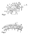
- Fig. 1 shows a housing cover strip segment 2 held directly on the turbine housing 1, which is arranged above the rotor blades 3 of the high-pressure turbine of a jet engine.
- the obliquely employed (stepped) blade tips 4 are formed as a bucket cover strip 5 with sealing tips 6, which form a narrow sealing gap 8 between them and the stepped sealing surface 7 of the housing cover strip segment 2.
- the housing cover band segment 2 is supported upstream of the turbine housing 1 and a stator blade segment 9, and assigned to a first retaining ring 10. Downstream of the housing cover band segment 2 spaced fastening hooks 11, 11 'are formed, whose counter to the flow direction angled leg 12 engages in a formed directly on the turbine housing 1 circumferential axial retaining groove 13.
- the housing cover strip segments 2 arranged next to one another on the inner circumference of the turbine housing 1 are secured downstream by a second retaining ring 14, which is arranged in a radial retaining groove 15 integrally formed on the turbine housing 1.
- a sealing plate 17 is provided, which is fixed by the second retaining ring 14 and a trained in the Gescousedeckbandsegmenten 2 groove 18.
- the rotor with the rotor blades 3 will be displaced by the distance s1 into a maximum possible rearward position.
- the housing cover strip segments 2 only have to be displaced axially at most by the displacement path s2.
- this relatively small displacement s2 of the GeHousedeckbandsegmente 2 is sufficient due to the formed at a distance fastening hooks 11, 11 'and according to the hook spacing and the hook width formed mounting pockets 19 to the fastening hooks 11, 11' from the axial retaining groove 13 to unlock.
- the mounting pockets 19 provide enough space to move the housing cover band segments 2 in relation to the sealing tips of the blades both radially and axially further stepwise and dismantle completely.
- the radial extent of the mounting pockets 19 depends on the oblique position or the radial gradation of the housing cover strip or the bucket cover strip 5 and the sealing tips 6 and can up to the inner contour of the turbine housing 1, so as to achieve a maximum weight saving in this area.
- the pressure P1 upstream of the sealing plate 17 is greater than the pressure P2 downstream thereof.
- the front pocket outlet edge 21 ends (FIG. Fig. 3 ) in the horizontal (middle) region of the retaining groove 15 and thus establishes a line contact between retaining ring 14 and turbine housing 1 for reliable sealing and maintaining the pressure gradient P1> P2. This is a slight reduction of the possible displacement path s2 connected by the amount s3.
- the required displacement s2 of the housing cover band segment 2 is not shortened by the amount s3, but in this case for sealing the leakage path and maintaining the pressure gradient P1> P2, the arrangement of an annular sealing element 23 in the retaining groove 15 required ( Fig. 4 ).
Landscapes
- Engineering & Computer Science (AREA)
- Mechanical Engineering (AREA)
- General Engineering & Computer Science (AREA)
- Turbine Rotor Nozzle Sealing (AREA)
Claims (8)
- Attache pour segments de virole de carter, qui relie les segments de virole de carter (2) d'une turbine haute pression d'un moteur à réaction avec un carter de turbine (1) d'une telle turbine haute pression, caractérisée en ce- que l'extrémité aval des segments de virole de carter (2) présente des crochets de fixation (11, 11') distants les uns des autres dans le sens circonférentiel, dont les branches (12) orientées vers l'amont s'engagent dans une gorge d'arrêt (13) axiale formée directement sur le carter de turbine (1),- que pour assurer la fixation axiale, sont associés aux crochets de fixation (11, 11') une plaque d'étanchéité (17) ainsi qu'un deuxième anneau de maintien (14) disposé dans une gorge (15) radiale de l'anneau de maintien du carter de turbine (1) s'étendant dans le sens circonférentiel, la plaque d'étanchéité (17) et le deuxième anneau de maintien (14) étant disposés en aval des crochets de fixation (11, 11'), et- que dans la gorge (15) de l'anneau de maintien sont prévus des ajours faisant office de poches de montage (19) en aval et radialement à l'extérieur des crochets de fixation (11, 11') et formés conformément à l'écartement et au dimensionnement des crochets de fixation (11, 11').
- Attache pour segments de virole de carter selon la revendication n° 1, caractérisée en ce que dans le sens radial, les poches de montage (19) sont façonnées jusqu'au contour intérieur du carter de turbine (1).
- Attache pour segments de virole de carter selon la revendication n° 1, caractérisée en ce que l'arête de sortie (21) des poches de montage (19) se termine en amont dans la zone radialement extérieure, horizontale de la gorge (15) de l'anneau de maintien et forme pour l'anneau de maintien (14) un bord d'étanchéité qui s'étend dans le sens circonférentiel et établit un contact linéaire entre l'anneau de maintien (14) et le carter de turbine (1).
- Attache pour segments de virole de carter selon la revendication n° 1, caractérisée en ce que les poches de montage (19) se terminent sur le bord avant (22) amont de la gorge (15) de l'anneau de maintien, sachant qu'un élément d'étanchéité (23) annulaire est disposé dans la gorge (15) de l'anneau de maintien.
- Attache pour segments de virole de carter selon la revendication n° 1, caractérisée en ce que le segment de virole de carter (2) s'appuie en amont sur un segment d'aube fixe (9) et sur le carter de turbine (1).
- Attache pour segments de virole de carter selon la revendication n° 1, caractérisée en ce que les poches de montage formées dans la gorge (15) de l'anneau de maintien s'étendent jusqu'à la face intérieure du carter de turbine (1) et présentent une largeur telle que leur largeur est supérieure à celle des crochets de fixation (11) et/ou à celle de crochets de fixation (11') adjacents les uns aux autres de segments de virole de carter (2) voisins.
- Attache pour segments de virole de carter selon la revendication n° 1, caractérisée en ce que les poches de montage (19) sont formées conformément à l'écartement et à la largeur des crochets de fixation (11, 11').
- Attache pour segments de virole de carter selon la revendication n° 1, caractérisée en ce que les poches de montage (19) quant à leur écartement et leur largeur sont dimensionnées de manière telle qu'elles permettent un déverrouillage des crochets de fixation (11, 11'), nécessaire pour le démontage des segments de virole de carter (2), par un déplacement axial et radial lorsque le rotor d'une turbine haute pression est monté.
Applications Claiming Priority (1)
| Application Number | Priority Date | Filing Date | Title |
|---|---|---|---|
| DE102007031711A DE102007031711A1 (de) | 2007-07-06 | 2007-07-06 | Gehäusedeckbandsegment-Aufhängung |
Publications (3)
| Publication Number | Publication Date |
|---|---|
| EP2011971A2 EP2011971A2 (fr) | 2009-01-07 |
| EP2011971A3 EP2011971A3 (fr) | 2011-08-31 |
| EP2011971B1 true EP2011971B1 (fr) | 2015-05-27 |
Family
ID=39791545
Family Applications (1)
| Application Number | Title | Priority Date | Filing Date |
|---|---|---|---|
| EP08158100.1A Ceased EP2011971B1 (fr) | 2007-07-06 | 2008-06-12 | Suspension d'un segment de virole de boîtier |
Country Status (3)
| Country | Link |
|---|---|
| US (1) | US8152455B2 (fr) |
| EP (1) | EP2011971B1 (fr) |
| DE (1) | DE102007031711A1 (fr) |
Families Citing this family (18)
| Publication number | Priority date | Publication date | Assignee | Title |
|---|---|---|---|---|
| US8740551B2 (en) * | 2009-08-18 | 2014-06-03 | Pratt & Whitney Canada Corp. | Blade outer air seal cooling |
| DE102010005153A1 (de) * | 2010-01-21 | 2011-07-28 | MTU Aero Engines GmbH, 80995 | Gehäusesystem für eine Axialströmungsmaschine |
| US9121301B2 (en) | 2012-03-20 | 2015-09-01 | General Electric Company | Thermal isolation apparatus |
| WO2013163581A1 (fr) * | 2012-04-27 | 2013-10-31 | General Electric Company | Système et procédé pour limiter le mouvement axial entre un étrier et un ensemble carénage dans un ensemble turbine |
| ES2579065T3 (es) * | 2012-12-21 | 2016-08-04 | Mtu Aero Engines Gmbh | Álabe de turbina con anillo de refuerzo y diente de corte |
| US9957830B2 (en) * | 2013-03-07 | 2018-05-01 | United Technologies Corporation | Hybrid passive and active tip clearance system |
| EP2826962B1 (fr) * | 2013-07-15 | 2016-06-22 | MTU Aero Engines GmbH | Turbomachine avec segments d'étanchéité et segments d'aube directrice |
| ES2636780T3 (es) * | 2013-08-22 | 2017-10-09 | Thyssenkrupp Steel Europe Ag | Procedimiento para la fabricación de un componente de acero |
| USD737868S1 (en) * | 2014-03-19 | 2015-09-01 | Tire Protection Solutions, Llc | Tire track shoe |
| USD737867S1 (en) * | 2014-03-19 | 2015-09-01 | Tire Protection Solutions, Llc | Tire track shoe |
| USD737337S1 (en) * | 2014-03-19 | 2015-08-25 | Tire Protection Solutions, Llc | Tire track shoe |
| USD737338S1 (en) * | 2014-03-19 | 2015-08-25 | Tire Protection Solutions, Llc | Tire track shoe |
| EP2949872A1 (fr) * | 2014-05-27 | 2015-12-02 | Siemens Aktiengesellschaft | Turbomachine avec un joint de séparation de fluide de travail, fluide de refroidissement de la turbomachine et utilisation de la turbomachine |
| US10215099B2 (en) * | 2015-02-06 | 2019-02-26 | United Technologies Corporation | System and method for limiting movement of a retainer ring of a gas turbine engine |
| JP6610876B2 (ja) * | 2015-11-11 | 2019-11-27 | 三菱自動車エンジニアリング株式会社 | 蒸散燃料処理装置を搭載した車両 |
| US10655491B2 (en) * | 2017-02-22 | 2020-05-19 | Rolls-Royce Corporation | Turbine shroud ring for a gas turbine engine with radial retention features |
| JP7061497B2 (ja) * | 2018-03-30 | 2022-04-28 | 三菱重工航空エンジン株式会社 | 航空機用ガスタービン |
| CN109611375B (zh) * | 2018-12-10 | 2020-09-25 | 中国航发四川燃气涡轮研究院 | 一种抑制小展弦比静子叶片振动的外环挂钩结构 |
Family Cites Families (13)
| Publication number | Priority date | Publication date | Assignee | Title |
|---|---|---|---|---|
| US3603599A (en) * | 1970-05-06 | 1971-09-07 | Gen Motors Corp | Cooled seal |
| GB2226365B (en) * | 1988-12-22 | 1993-03-10 | Rolls Royce Plc | Turbomachine clearance control |
| US5333995A (en) * | 1993-08-09 | 1994-08-02 | General Electric Company | Wear shim for a turbine engine |
| US5639210A (en) * | 1995-10-23 | 1997-06-17 | United Technologies Corporation | Rotor blade outer tip seal apparatus |
| EP0844369B1 (fr) * | 1996-11-23 | 2002-01-30 | ROLLS-ROYCE plc | Assemblage d'un rotor à aubes et de son carter |
| US5971703A (en) * | 1997-12-05 | 1999-10-26 | Pratt & Whitney Canada Inc. | Seal assembly for a gas turbine engine |
| DE50003360D1 (de) * | 1999-03-24 | 2003-09-25 | Siemens Ag | Abdeckelement und anordnung mit einem abdeckelement und mit einer tragstruktur |
| DE102004016222A1 (de) * | 2004-03-26 | 2005-10-06 | Rolls-Royce Deutschland Ltd & Co Kg | Anordnung zur selbsttätigen Laufspalteinstellung bei einer zwei- oder mehrstufigen Turbine |
| US7217089B2 (en) * | 2005-01-14 | 2007-05-15 | Pratt & Whitney Canada Corp. | Gas turbine engine shroud sealing arrangement |
| DE102005013798A1 (de) | 2005-03-24 | 2006-09-28 | Alstom Technology Ltd. | Wärmestausegment zum Abdichten eines Strömungskanals einer Strömungsrotationsmaschine |
| EP1707749B1 (fr) | 2005-03-28 | 2012-02-22 | United Technologies Corporation | Ensemble de joints externes d'aubes de turbine |
| US7721433B2 (en) * | 2005-03-28 | 2010-05-25 | United Technologies Corporation | Blade outer seal assembly |
| US7334980B2 (en) * | 2005-03-28 | 2008-02-26 | United Technologies Corporation | Split ring retainer for turbine outer air seal |
-
2007
- 2007-07-06 DE DE102007031711A patent/DE102007031711A1/de not_active Withdrawn
-
2008
- 2008-06-12 EP EP08158100.1A patent/EP2011971B1/fr not_active Ceased
- 2008-07-03 US US12/216,459 patent/US8152455B2/en not_active Expired - Fee Related
Also Published As
| Publication number | Publication date |
|---|---|
| US20090010758A1 (en) | 2009-01-08 |
| US8152455B2 (en) | 2012-04-10 |
| EP2011971A2 (fr) | 2009-01-07 |
| DE102007031711A1 (de) | 2009-01-08 |
| EP2011971A3 (fr) | 2011-08-31 |
Similar Documents
| Publication | Publication Date | Title |
|---|---|---|
| EP2011971B1 (fr) | Suspension d'un segment de virole de boîtier | |
| DE69926574T2 (de) | Turbinenleitgitter mit einem Kühlluftleitsystem | |
| DE602004002078T2 (de) | Innen gekühltes Leitschaufelpaar | |
| DE3537043C2 (de) | Kühlbare Dichtvorrichtung für eine Statorbaugruppe | |
| EP2179143B1 (fr) | Refroidissement de fente entre une paroi de chambre de combustion et une paroi de turbine d'une installation de turbine à gaz | |
| DE102007025006A1 (de) | Doppelwellen-Gasturbine | |
| EP1413831A1 (fr) | Chambre de combustion annulaire pour turbine à gaz et turbine à gaz | |
| DE3700668C2 (de) | Übergangskanaldichtvorrichtung | |
| DE3027712A1 (de) | Turbinenlaeufer fuer gasturbinen | |
| EP2918913B1 (fr) | Chambre de combustion d'une turbine à gaz | |
| DE102014117262A1 (de) | L-Bürstendichtung für Turbomaschinenanwendungen | |
| DE102009044102A1 (de) | Geteilte Verkleidung für eine Gasturbine | |
| EP3152407B1 (fr) | Couronne d'aubes fixes, bague intérieure et turbomachine | |
| EP1694943B1 (fr) | Turbomachine | |
| EP1736635B1 (fr) | Système de transfert d'air entre le compresseur et la turbine d'une turbine à gaz | |
| EP1389265A1 (fr) | Anneau d'enveloppe | |
| DE102012201050A1 (de) | Dichtungsanordnung, Verfahren sowie Strömungsmaschine | |
| DE102016100043A1 (de) | Turbinendeckbandbaugruppe | |
| DE102015120128A1 (de) | Turbinenradabdeckplattenmontierte Gasturbinen-Zwischenstufendichtung | |
| EP2526263B1 (fr) | Système de boîtier pour une turbomachine axiale | |
| DE3017035A1 (de) | Rotoranordnung mit mehrstufiger scheibe | |
| EP2650520B1 (fr) | Turbine à gaz d'aéronef avec canal de décharge dans un pied d'aube de guidage d'un canal de flux secondaire | |
| EP1917419B1 (fr) | Dispositif d'aube directrice d'une turbomachine | |
| CH698921B1 (de) | Strömungsmaschine. | |
| DE102013210171A1 (de) | Strukturbaugruppe für eine Strömungsmaschine |
Legal Events
| Date | Code | Title | Description |
|---|---|---|---|
| PUAI | Public reference made under article 153(3) epc to a published international application that has entered the european phase |
Free format text: ORIGINAL CODE: 0009012 |
|
| AK | Designated contracting states |
Kind code of ref document: A2 Designated state(s): AT BE BG CH CY CZ DE DK EE ES FI FR GB GR HR HU IE IS IT LI LT LU LV MC MT NL NO PL PT RO SE SI SK TR |
|
| AX | Request for extension of the european patent |
Extension state: AL BA MK RS |
|
| PUAL | Search report despatched |
Free format text: ORIGINAL CODE: 0009013 |
|
| AK | Designated contracting states |
Kind code of ref document: A3 Designated state(s): AT BE BG CH CY CZ DE DK EE ES FI FR GB GR HR HU IE IS IT LI LT LU LV MC MT NL NO PL PT RO SE SI SK TR |
|
| AX | Request for extension of the european patent |
Extension state: AL BA MK RS |
|
| RIC1 | Information provided on ipc code assigned before grant |
Ipc: F01D 11/08 20060101ALI20110726BHEP Ipc: F01D 25/24 20060101AFI20110726BHEP |
|
| 17P | Request for examination filed |
Effective date: 20120224 |
|
| AKX | Designation fees paid |
Designated state(s): DE FR GB |
|
| GRAP | Despatch of communication of intention to grant a patent |
Free format text: ORIGINAL CODE: EPIDOSNIGR1 |
|
| INTG | Intention to grant announced |
Effective date: 20150123 |
|
| GRAS | Grant fee paid |
Free format text: ORIGINAL CODE: EPIDOSNIGR3 |
|
| GRAA | (expected) grant |
Free format text: ORIGINAL CODE: 0009210 |
|
| AK | Designated contracting states |
Kind code of ref document: B1 Designated state(s): DE FR GB |
|
| REG | Reference to a national code |
Ref country code: GB Ref legal event code: FG4D Free format text: NOT ENGLISH |
|
| REG | Reference to a national code |
Ref country code: DE Ref legal event code: R096 Ref document number: 502008013014 Country of ref document: DE |
|
| REG | Reference to a national code |
Ref country code: DE Ref legal event code: R097 Ref document number: 502008013014 Country of ref document: DE |
|
| PLBE | No opposition filed within time limit |
Free format text: ORIGINAL CODE: 0009261 |
|
| STAA | Information on the status of an ep patent application or granted ep patent |
Free format text: STATUS: NO OPPOSITION FILED WITHIN TIME LIMIT |
|
| 26N | No opposition filed |
Effective date: 20160301 |
|
| REG | Reference to a national code |
Ref country code: FR Ref legal event code: PLFP Year of fee payment: 9 |
|
| REG | Reference to a national code |
Ref country code: FR Ref legal event code: PLFP Year of fee payment: 10 |
|
| REG | Reference to a national code |
Ref country code: FR Ref legal event code: PLFP Year of fee payment: 11 |
|
| PGFP | Annual fee paid to national office [announced via postgrant information from national office to epo] |
Ref country code: FR Payment date: 20190625 Year of fee payment: 12 |
|
| PGFP | Annual fee paid to national office [announced via postgrant information from national office to epo] |
Ref country code: DE Payment date: 20190627 Year of fee payment: 12 Ref country code: GB Payment date: 20190627 Year of fee payment: 12 |
|
| REG | Reference to a national code |
Ref country code: DE Ref legal event code: R082 Ref document number: 502008013014 Country of ref document: DE |
|
| REG | Reference to a national code |
Ref country code: DE Ref legal event code: R119 Ref document number: 502008013014 Country of ref document: DE |
|
| GBPC | Gb: european patent ceased through non-payment of renewal fee |
Effective date: 20200612 |
|
| PG25 | Lapsed in a contracting state [announced via postgrant information from national office to epo] |
Ref country code: FR Free format text: LAPSE BECAUSE OF NON-PAYMENT OF DUE FEES Effective date: 20200630 Ref country code: GB Free format text: LAPSE BECAUSE OF NON-PAYMENT OF DUE FEES Effective date: 20200612 |
|
| PG25 | Lapsed in a contracting state [announced via postgrant information from national office to epo] |
Ref country code: DE Free format text: LAPSE BECAUSE OF NON-PAYMENT OF DUE FEES Effective date: 20210101 |