EP2012005A2 - Wasserturbine - Google Patents
Wasserturbine Download PDFInfo
- Publication number
- EP2012005A2 EP2012005A2 EP08011785A EP08011785A EP2012005A2 EP 2012005 A2 EP2012005 A2 EP 2012005A2 EP 08011785 A EP08011785 A EP 08011785A EP 08011785 A EP08011785 A EP 08011785A EP 2012005 A2 EP2012005 A2 EP 2012005A2
- Authority
- EP
- European Patent Office
- Prior art keywords
- runner
- blades
- turbine according
- nozzles
- turbine
- Prior art date
- Legal status (The legal status is an assumption and is not a legal conclusion. Google has not performed a legal analysis and makes no representation as to the accuracy of the status listed.)
- Withdrawn
Links
- 239000012530 fluid Substances 0.000 claims abstract description 30
- XLYOFNOQVPJJNP-UHFFFAOYSA-N water Substances O XLYOFNOQVPJJNP-UHFFFAOYSA-N 0.000 claims description 5
- 230000007423 decrease Effects 0.000 claims description 3
- 238000003491 array Methods 0.000 claims 1
- 230000015572 biosynthetic process Effects 0.000 claims 1
- 230000008859 change Effects 0.000 description 7
- 230000008901 benefit Effects 0.000 description 4
- 238000012423 maintenance Methods 0.000 description 4
- 238000004519 manufacturing process Methods 0.000 description 3
- 230000004048 modification Effects 0.000 description 3
- 238000012986 modification Methods 0.000 description 3
- 238000006424 Flood reaction Methods 0.000 description 2
- 230000003247 decreasing effect Effects 0.000 description 2
- 230000009471 action Effects 0.000 description 1
- 238000006243 chemical reaction Methods 0.000 description 1
- 238000006757 chemical reactions by type Methods 0.000 description 1
- 238000009792 diffusion process Methods 0.000 description 1
- 238000007599 discharging Methods 0.000 description 1
- 230000003628 erosive effect Effects 0.000 description 1
- 238000005381 potential energy Methods 0.000 description 1
- 230000000750 progressive effect Effects 0.000 description 1
- 230000009467 reduction Effects 0.000 description 1
- 238000005096 rolling process Methods 0.000 description 1
- 238000011144 upstream manufacturing Methods 0.000 description 1
Images




Classifications
-
- F—MECHANICAL ENGINEERING; LIGHTING; HEATING; WEAPONS; BLASTING
- F03—MACHINES OR ENGINES FOR LIQUIDS; WIND, SPRING, OR WEIGHT MOTORS; PRODUCING MECHANICAL POWER OR A REACTIVE PROPULSIVE THRUST, NOT OTHERWISE PROVIDED FOR
- F03B—MACHINES OR ENGINES FOR LIQUIDS
- F03B1/00—Engines of impulse type, i.e. turbines with jets of high-velocity liquid impinging on blades or like rotors, e.g. Pelton wheels; Parts or details peculiar thereto
- F03B1/02—Buckets; Bucket-carrying rotors
-
- F—MECHANICAL ENGINEERING; LIGHTING; HEATING; WEAPONS; BLASTING
- F03—MACHINES OR ENGINES FOR LIQUIDS; WIND, SPRING, OR WEIGHT MOTORS; PRODUCING MECHANICAL POWER OR A REACTIVE PROPULSIVE THRUST, NOT OTHERWISE PROVIDED FOR
- F03B—MACHINES OR ENGINES FOR LIQUIDS
- F03B1/00—Engines of impulse type, i.e. turbines with jets of high-velocity liquid impinging on blades or like rotors, e.g. Pelton wheels; Parts or details peculiar thereto
- F03B1/04—Nozzles; Nozzle-carrying members
-
- F—MECHANICAL ENGINEERING; LIGHTING; HEATING; WEAPONS; BLASTING
- F05—INDEXING SCHEMES RELATING TO ENGINES OR PUMPS IN VARIOUS SUBCLASSES OF CLASSES F01-F04
- F05B—INDEXING SCHEME RELATING TO WIND, SPRING, WEIGHT, INERTIA OR LIKE MOTORS, TO MACHINES OR ENGINES FOR LIQUIDS COVERED BY SUBCLASSES F03B, F03D AND F03G
- F05B2240/00—Components
- F05B2240/20—Rotors
- F05B2240/24—Rotors for turbines
- F05B2240/241—Rotors for turbines of impulse type
-
- F—MECHANICAL ENGINEERING; LIGHTING; HEATING; WEAPONS; BLASTING
- F05—INDEXING SCHEMES RELATING TO ENGINES OR PUMPS IN VARIOUS SUBCLASSES OF CLASSES F01-F04
- F05B—INDEXING SCHEME RELATING TO WIND, SPRING, WEIGHT, INERTIA OR LIKE MOTORS, TO MACHINES OR ENGINES FOR LIQUIDS COVERED BY SUBCLASSES F03B, F03D AND F03G
- F05B2240/00—Components
- F05B2240/40—Use of a multiplicity of similar components
-
- F—MECHANICAL ENGINEERING; LIGHTING; HEATING; WEAPONS; BLASTING
- F05—INDEXING SCHEMES RELATING TO ENGINES OR PUMPS IN VARIOUS SUBCLASSES OF CLASSES F01-F04
- F05B—INDEXING SCHEME RELATING TO WIND, SPRING, WEIGHT, INERTIA OR LIKE MOTORS, TO MACHINES OR ENGINES FOR LIQUIDS COVERED BY SUBCLASSES F03B, F03D AND F03G
- F05B2250/00—Geometry
- F05B2250/10—Geometry two-dimensional
- F05B2250/14—Geometry two-dimensional elliptical
- F05B2250/141—Geometry two-dimensional elliptical circular
-
- Y—GENERAL TAGGING OF NEW TECHNOLOGICAL DEVELOPMENTS; GENERAL TAGGING OF CROSS-SECTIONAL TECHNOLOGIES SPANNING OVER SEVERAL SECTIONS OF THE IPC; TECHNICAL SUBJECTS COVERED BY FORMER USPC CROSS-REFERENCE ART COLLECTIONS [XRACs] AND DIGESTS
- Y02—TECHNOLOGIES OR APPLICATIONS FOR MITIGATION OR ADAPTATION AGAINST CLIMATE CHANGE
- Y02E—REDUCTION OF GREENHOUSE GAS [GHG] EMISSIONS, RELATED TO ENERGY GENERATION, TRANSMISSION OR DISTRIBUTION
- Y02E10/00—Energy generation through renewable energy sources
- Y02E10/20—Hydro energy
Definitions
- the present invention refers to hydraulic turbines, particularly of the impulse type, in which the available pressure potential energy is transformed integrally into kinetic energy in the distributor but not in the runner.
- the turbine according to the invention turns out to be particularly simple from a constructive point of view, to full advantage of the reduction of manufacturing and maintenance costs, and of the reliability thereof in operation. Since the turbine of the invention is a full action turbine, the blades of its runner or of its runners, never work in a suction conditions, as instead happens for reaction turbines, so that they do not run the risk to undergo cavitation with a resulting erosion of the blades.
- the turbine of the invention does not require movable deflector members associated with the distributor for correctly directing the flow of fluid to the blades of the runner, only the position of the nozzles associated with the distributor being able to determine the correct delivery direction of the fluid towards the blades of the runner, which contributes to simplify the turbine structure and to minimize losses of the machine which may derive from frictions in the distributor, with a resulting better efficiency which turns out to be therefore close to the theoretical maximum.
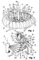
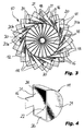
- a runner of the turbine is indicated 10 in its whole.
- the runner 10 is rotatably mounted on a shaft 12 having an axis A, preferably arranged vertically.
- the elements of the structure which are adapted to rotatably support the shaft 12 and the runner 10 are not shown in detail since they are within the reach of the skilled person.
- a plurality of diffuser nozzles 20 is associated to the runner 10.
- the number of nozzles 20 may be equal to the number of the blades 14, or lower than it.
- one nozzle 20 is provided at each two blades 14, in such a manner that the number of the nozzles 20 is half the number of the blades 14.
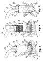
- the runner 10 is associated to a cylindrical distributor unit 34, coaxial with the shaft 12, which includes an adjusting device for adjusting the flow rate of the fluid delivered through the nozzles 20 towards the runner 10.
- the turbine unit including the runner 10, the nozzles 20 and the distributor 34, as well as the members associated thereto, is indicated 32 in its whole.
- the distributor 34 is sealingly closed at its opposite ends by a pair of plates, the upper of which is indicated 35 in the figures.
- a duct 36 for feeding the fluid to the turbine 32 extends from the plate 35, such a duct being typically connected with a watercourse from which the fluid needed for the operation of the turbine 32 is taken.
- a cylindrical valve member 38 (shown in a darker color in figure 6 and for which three different positions are identified in dashed lines), which is provided with a pair of fixed push rods 40 projecting outside the slab 35, is slidably mounted inside the distributor 34.
- By operating on the rods 40 it is possible to change the axial position of the valve member 38 with respect to the distributor 34, as indicated by arrow B of figure 6 , in order to occlude, according to the position thereof, partially the holes of the side surface of the distributor 34, with the aim of preventing or shutting the feeding of fluid to some of the feeding ducts of the nozzles 20, in order to adjust the flow rate fed to the runner 10.
- Figure 7 shows an alternative arrangement of the nozzles 20 of the distributor 34, with respect to that shown in figures 5 and 6 .
- the nozzles 20 are here arranged with respect to the runner 10, according to diametrically opposite pairs, whose length of the portions 20b decreases alternatively in the circumferential direction.
- the two nozzles 20 having the longer portions 20b, which are different to each other are arranged at diametrally opposite locations of the distributor 34 and, advancing for example in the counter-clockwise direction of the distributor 34, the pair of nozzles 20 having the shorter portions 20b arranged at diametrically opposite locations follow, then a pair of diametrically opposite nozzles 20 whose portions 20b are the longest except for the nozzles 20 mentioned first, and so on.
- the adjustment of the axial position of the valve member 38 in one of its directions of sliding, for example in the direction from above to below, allows to occlude gradually the nozzles 20 which have a decreasing length and are arranged at diametrally opposite location of the runner 10, so that the load applied to the blades 14 by the fluid delivered from the nozzles 20 turns out to be substantially balanced in all the adjustment conditions of the flow rate.
- a sealed case (indicated 42 in figure 8 ) from the lower portion of which, to the outlet, a diverging water pipe 44, a so-called “aspirator-diffuser pipe”, extends, which is intended to be immerged in the watercourse in which the turbine 32 releases the used fluid.
- a suction is determined inside of the case 42, which allows to recover almost integrally the height of fall that otherwise could not be exploited.
- FIGS 9 and 10 show a modification of the shape of the turbine blades, here indicated 14a, particularly suitable for a runner 10 arranged with its axis A horizontal.
- Each blade 14a comprises a pair of active surfaces 22a and 22b aligned and opposite to each other, having a constant cross-section, which define respective arched paths for the fluid, and which extend between respective leading portions 24a and 24b defined by a common diverging portion 23 in front of which the outflow portions 20a of the nozzles 20 are arranged.
- Each blade 14a at opposite sides with respect to the diverging portion 23, has respective trailing portions 26a and 26b equally spaced with respect to the general plane of the runner, and therefore with respect to the plane on which the outflow portions 20a lie.
- the active surfaces 22a and 22b of the blades 14a are preferably flat and arched, with a semicircular or semielliptic shape.
- the pair of active surfaces 22a and 22b of a same blade 14a is delimited sideways by two flat, parallel and substantially equal side walls 21a, one of which is connected with the relevant primary arm 16 of the blade 14a, the walls 21a of each blade 14a being each one fixed to a wall 21a of an adjacent blade 14a.
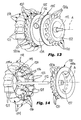
- FIGS 11 to 14 show a second embodiment of the turbine according to the invention, here indicated 132.
- the same numeral references of the previous embodiment have been used in order to indicate parts equal or similar thereto, with their numbers increased by 100.
- the turbine 132 includes a pair of equal runners 110, both fastened on a same shaft 112 having an axis A, particularly intended to be arranged horizontal, the runners being arranged at opposite sides of a substantially cylindrical distributor unit 134.
- Each runner 110 has a crown of blades 114 each of which defines an arched active surface 122, preferably flat and having a semicircular or semielliptic shape, which extends between a leading portion 124 and a trailing portion 126, and is delimited sideways by walls 121.
- the leading portions 124 of the blades 114 are arranged substantially at the same level of a general plane of the respective runner 110 on which the outflow portions 120a of a plurality of nozzles 120 lie, while the trailing portions 126 of the blades 114 are arranged on a plane parallel and axially spaced with respect to the general plane of the same runner 110.
- the nozzles 120 associated to a runner 110 have a rectilinear shape and extend from an annular body 135 coaxial with the axis A, secured beside the distributor unit 134 and sealingly closed at the relevant runner 110 by means of a head 137.
- Each annular body 135 has a series of through holes 135a, through which the fluid contained in the distributor unit 134 is fed to the nozzles 120 in order to be delivered to the blades 114.
- each annular body 135 is associated with a cylindrical valve member (not shown in the figures) which may be moved axially as a result of a command received from the outside of the turbine 132, in a manner conceptually similar to that described in connection with the previous embodiment, in order to adjust the flow rate admitted to the nozzles 120 and sent to the blades 114.
- the annular member 119 has a plurality of spokes 118 for connecting it with a hub 118a coaxial with the shaft 112.
- FIGS 15 to 19 show a third embodiment of a turbine according to the invention, which is indicated 232 in its whole.
- the same numeral references of the first embodiment have been used to indicate parts equal or similar thereto, with their numbers increased by 200.
- the turbine 232 comprises a runner 210 rotatably mounted on a shaft 212 having an axis A, particularly intended to be arranged horizontal.
- Rolling bearings 248 (only one of which can be seen in figure 15 ) are mounted at the ends of the shaft 212, which are associated with a support structure 245 including a base 246 and a pair of vertical uprights 247.
- a plurality of support members 249 (only one of which can be seen in figure 15 ), adapted to support a respective nozzle 220, is fixed to each of the uprights 247.
- each support member 249 includes an annular portion clamped on the transfer portion 220b of a respective nozzle 220, so as to hold the trailing portion 220a of the respective nozzle 220, which is directed towards the outside of the runner and along a direction parallel to and spaced from the radial direction, inside the runner 210 in a zone between the blades 214 and the axis of rotation A, so that the nozzles 220 face the leading portions 224 of the blades 214.
- the blades 214 of the runner 210 are secured to an annular support member 219 connected to a circular hub 218, coaxial with the shaft 212, by a plurality of spokes 216 ( figure 17 ).
- the outflow portions 220a of the nozzles 220 and the leading portions 224 of the blades 214 are substantially arranged at the same level of a general plane of the runner 210 which corresponds to a median plane of the annular member 219.
- Each blade 214 defines a substantially spoon shaped concave active surface 222 extending between the relevant leading portion 224 and the relevant trailing portion 226, the leading portion 224 being generally narrow, and the blade progressively widening towards the trailing portion 226.
- a rib 227 intended to be inserted in a corresponding seat of the inner surface of the annular support member 219, for allowing to secure the blades on the annular member 219, exends from the back of the blades 214 at the side opposite to their active surface 222.
- the blades 214 are arranged alternatively opposed, in such a manner that the trailing portion 226 of one blade 214 is arranged at the side opposite to the trailing portions 226 of two adjacent blades 214.
- the trailing portions 226 of the blades 214 of the runner 210 lie on two parallel planes equally spaced from the general plane of the runner 210.
- the nozzles 220 can be advantageously associated with a cylindrical distributor unit (not shown), similar to that described in connecton with the first embodiment and conveniently provided with adjustement means for adjusting the flow rate of the fluid delivered, which include for example a cylindrical valve member movable with respect to the distributor unit.
Landscapes
- Engineering & Computer Science (AREA)
- Chemical & Material Sciences (AREA)
- Combustion & Propulsion (AREA)
- Mechanical Engineering (AREA)
- General Engineering & Computer Science (AREA)
- Hydraulic Turbines (AREA)
- Lubrication Of Internal Combustion Engines (AREA)
- Valve Device For Special Equipments (AREA)
Applications Claiming Priority (1)
| Application Number | Priority Date | Filing Date | Title |
|---|---|---|---|
| IT000482A ITTO20070482A1 (it) | 2007-07-02 | 2007-07-02 | Turbina idraulica |
Publications (1)
| Publication Number | Publication Date |
|---|---|
| EP2012005A2 true EP2012005A2 (de) | 2009-01-07 |
Family
ID=39708656
Family Applications (1)
| Application Number | Title | Priority Date | Filing Date |
|---|---|---|---|
| EP08011785A Withdrawn EP2012005A2 (de) | 2007-07-02 | 2008-06-30 | Wasserturbine |
Country Status (2)
| Country | Link |
|---|---|
| EP (1) | EP2012005A2 (de) |
| IT (1) | ITTO20070482A1 (de) |
Cited By (5)
| Publication number | Priority date | Publication date | Assignee | Title |
|---|---|---|---|---|
| WO2010108385A1 (zh) * | 2009-03-24 | 2010-09-30 | Huang Guohong | 发电动力机 |
| EP2574770A3 (de) * | 2011-09-30 | 2013-05-15 | Robert Bosch Gmbh | Freistrahlturbine |
| DE102012100669A1 (de) * | 2012-01-26 | 2013-08-01 | Florian Ziller | Impulsturbinenanorndung |
| DE102015222244A1 (de) * | 2015-11-11 | 2017-05-11 | Mahle International Gmbh | Hydraulikantrieb |
| CN110446827A (zh) * | 2017-03-27 | 2019-11-12 | 宋吉奉 | 在密封的涡轮内部包括喷嘴的向心力涡轮装置 |
-
2007
- 2007-07-02 IT IT000482A patent/ITTO20070482A1/it unknown
-
2008
- 2008-06-30 EP EP08011785A patent/EP2012005A2/de not_active Withdrawn
Cited By (6)
| Publication number | Priority date | Publication date | Assignee | Title |
|---|---|---|---|---|
| WO2010108385A1 (zh) * | 2009-03-24 | 2010-09-30 | Huang Guohong | 发电动力机 |
| EP2574770A3 (de) * | 2011-09-30 | 2013-05-15 | Robert Bosch Gmbh | Freistrahlturbine |
| DE102012100669A1 (de) * | 2012-01-26 | 2013-08-01 | Florian Ziller | Impulsturbinenanorndung |
| DE102015222244A1 (de) * | 2015-11-11 | 2017-05-11 | Mahle International Gmbh | Hydraulikantrieb |
| CN110446827A (zh) * | 2017-03-27 | 2019-11-12 | 宋吉奉 | 在密封的涡轮内部包括喷嘴的向心力涡轮装置 |
| EP3604737A4 (de) * | 2017-03-27 | 2020-10-28 | Kil Bong Song | Zentripetale turbine mit düsen in einer versiegelten turbine |
Also Published As
| Publication number | Publication date |
|---|---|
| ITTO20070482A1 (it) | 2009-01-03 |
Similar Documents
| Publication | Publication Date | Title |
|---|---|---|
| EP1583902B1 (de) | Ventil und verfahren zur druckreduzierung und zur leistungserzeugung | |
| NO341873B1 (no) | Aksjonsturbinanordning for toveis strøm | |
| US8546965B2 (en) | Reduced pressure differential hydroelectric turbine system | |
| US8067850B2 (en) | Method for creating a low fluid pressure differential electrical generating system | |
| JP6399406B2 (ja) | 発電装置 | |
| WO2007142709A1 (en) | Liquid control jet during part load operation in a hydraulic turbine | |
| US20110173976A1 (en) | Energy generating system using a plurality of waterwheels | |
| KR102637470B1 (ko) | 양식장 배출수의 유량과 수두에 따라 수차시스템의 안내깃과 베인의 각도변경이 가능한 조립식 소수력발전용 임펠러 시스템 | |
| KR20040062670A (ko) | 변형가능한 단면을 갖는 물 터빈을 포함하는 유관 | |
| ITTO20070482A1 (it) | Turbina idraulica | |
| US20080217920A1 (en) | Turbine with tube arrangement and method of preventing detachment of a fluid flow | |
| EP0962653B1 (de) | Freistrahlturbine | |
| WO2015071094A1 (en) | Aerating system for hydraulic turbine | |
| EP2436880B1 (de) | Verfahren zum Modifizieren einer Dampfturbine | |
| EP2954196B1 (de) | Wasserturbine mit reaktionsrotor | |
| US20130302187A1 (en) | Pump Turbine Installation | |
| US20050019153A1 (en) | Impulse turbine, particularly of the reversible type | |
| EP3394423B1 (de) | Laufrad für eine hydraulische turbine oder pumpe und verfahren zum betrieb eines solchen laufrads | |
| JP2002295356A (ja) | 多段形水力発電装置 | |
| CN111456882A (zh) | 渐进式水轮机 | |
| MXPA97002760A (en) | Set of nozzle for a water turbine dechorro li | |
| KR102902763B1 (ko) | 소수력 발전 시스템 | |
| CN222390396U (zh) | 一种敞开式引水系统 | |
| SE9600118A0 (sv) | Turbin för elkraftverk | |
| KR20140000382A (ko) | 반작용식 터빈 시스템 |
Legal Events
| Date | Code | Title | Description |
|---|---|---|---|
| PUAI | Public reference made under article 153(3) epc to a published international application that has entered the european phase |
Free format text: ORIGINAL CODE: 0009012 |
|
| AK | Designated contracting states |
Kind code of ref document: A2 Designated state(s): AT BE BG CH CY CZ DE DK EE ES FI FR GB GR HR HU IE IS IT LI LT LU LV MC MT NL NO PL PT RO SE SI SK TR |
|
| AX | Request for extension of the european patent |
Extension state: AL BA MK RS |
|
| STAA | Information on the status of an ep patent application or granted ep patent |
Free format text: STATUS: THE APPLICATION IS DEEMED TO BE WITHDRAWN |
|
| 18D | Application deemed to be withdrawn |
Effective date: 20110104 |