EP2012009A2 - Return valve insert for a fuel dosing pump - Google Patents
Return valve insert for a fuel dosing pump Download PDFInfo
- Publication number
- EP2012009A2 EP2012009A2 EP08010914A EP08010914A EP2012009A2 EP 2012009 A2 EP2012009 A2 EP 2012009A2 EP 08010914 A EP08010914 A EP 08010914A EP 08010914 A EP08010914 A EP 08010914A EP 2012009 A2 EP2012009 A2 EP 2012009A2
- Authority
- EP
- European Patent Office
- Prior art keywords
- insert
- check valve
- sealing element
- insert body
- valve insert
- Prior art date
- Legal status (The legal status is an assumption and is not a legal conclusion. Google has not performed a legal analysis and makes no representation as to the accuracy of the status listed.)
- Granted
Links
Images
Classifications
-
- F—MECHANICAL ENGINEERING; LIGHTING; HEATING; WEAPONS; BLASTING
- F16—ENGINEERING ELEMENTS AND UNITS; GENERAL MEASURES FOR PRODUCING AND MAINTAINING EFFECTIVE FUNCTIONING OF MACHINES OR INSTALLATIONS; THERMAL INSULATION IN GENERAL
- F16K—VALVES; TAPS; COCKS; ACTUATING-FLOATS; DEVICES FOR VENTING OR AERATING
- F16K27/00—Construction of housing; Use of materials therefor
- F16K27/02—Construction of housing; Use of materials therefor of lift valves
- F16K27/0209—Check valves or pivoted valves
-
- F—MECHANICAL ENGINEERING; LIGHTING; HEATING; WEAPONS; BLASTING
- F04—POSITIVE - DISPLACEMENT MACHINES FOR LIQUIDS; PUMPS FOR LIQUIDS OR ELASTIC FLUIDS
- F04B—POSITIVE-DISPLACEMENT MACHINES FOR LIQUIDS; PUMPS
- F04B13/00—Pumps specially modified to deliver fixed or variable measured quantities
-
- F—MECHANICAL ENGINEERING; LIGHTING; HEATING; WEAPONS; BLASTING
- F04—POSITIVE - DISPLACEMENT MACHINES FOR LIQUIDS; PUMPS FOR LIQUIDS OR ELASTIC FLUIDS
- F04B—POSITIVE-DISPLACEMENT MACHINES FOR LIQUIDS; PUMPS
- F04B17/00—Pumps characterised by combination with, or adaptation to, specific driving engines or motors
- F04B17/003—Pumps characterised by combination with, or adaptation to, specific driving engines or motors driven by piezoelectric means
-
- F—MECHANICAL ENGINEERING; LIGHTING; HEATING; WEAPONS; BLASTING
- F04—POSITIVE - DISPLACEMENT MACHINES FOR LIQUIDS; PUMPS FOR LIQUIDS OR ELASTIC FLUIDS
- F04B—POSITIVE-DISPLACEMENT MACHINES FOR LIQUIDS; PUMPS
- F04B53/00—Component parts, details or accessories not provided for in, or of interest apart from, groups F04B1/00 - F04B23/00 or F04B39/00 - F04B47/00
- F04B53/10—Valves; Arrangement of valves
- F04B53/1002—Ball valves
-
- F—MECHANICAL ENGINEERING; LIGHTING; HEATING; WEAPONS; BLASTING
- F04—POSITIVE - DISPLACEMENT MACHINES FOR LIQUIDS; PUMPS FOR LIQUIDS OR ELASTIC FLUIDS
- F04B—POSITIVE-DISPLACEMENT MACHINES FOR LIQUIDS; PUMPS
- F04B53/00—Component parts, details or accessories not provided for in, or of interest apart from, groups F04B1/00 - F04B23/00 or F04B39/00 - F04B47/00
- F04B53/16—Casings; Cylinders; Cylinder liners or heads; Fluid connections
- F04B53/162—Adaptations of cylinders
-
- F—MECHANICAL ENGINEERING; LIGHTING; HEATING; WEAPONS; BLASTING
- F04—POSITIVE - DISPLACEMENT MACHINES FOR LIQUIDS; PUMPS FOR LIQUIDS OR ELASTIC FLUIDS
- F04B—POSITIVE-DISPLACEMENT MACHINES FOR LIQUIDS; PUMPS
- F04B53/00—Component parts, details or accessories not provided for in, or of interest apart from, groups F04B1/00 - F04B23/00 or F04B39/00 - F04B47/00
- F04B53/22—Arrangements for enabling ready assembly or disassembly
-
- F—MECHANICAL ENGINEERING; LIGHTING; HEATING; WEAPONS; BLASTING
- F16—ENGINEERING ELEMENTS AND UNITS; GENERAL MEASURES FOR PRODUCING AND MAINTAINING EFFECTIVE FUNCTIONING OF MACHINES OR INSTALLATIONS; THERMAL INSULATION IN GENERAL
- F16J—PISTONS; CYLINDERS; SEALINGS
- F16J15/00—Sealings
- F16J15/02—Sealings between relatively-stationary surfaces
- F16J15/14—Sealings between relatively-stationary surfaces by means of granular or plastic material, or fluid
Definitions
- the present invention relates to a check valve insert for a fuel metering pump, in particular for a vehicle heater, comprising an insert body with a flow channel extending therethrough, wherein the insert body is formed in its two end portions for liquid-tight connection and between its end regions has a valve seat for a check valve body.
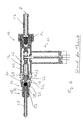
- FIG. 1 shows this fuel metering pump, which serves to promote the liquid fuel from a reservoir to a combustion chamber in a fuel-powered vehicle heater.
- the liquid fuel is received from a line not shown in the metering pump 10 via an inlet port 12.
- the fuel then passes, after flowing through a filter 14, into a space region 16 which is open via openings 18 to a pumping chamber 20.
- a reciprocating in the axial direction, relative to a longitudinal center axis A, reciprocating pump piston 22 which is driven by a piezoelectrically effective drive unit 24, displaced in a movement to the right in Fig.
- the check valve 26 is constructed with a check valve insert 30, which is elongated in the direction of the longitudinal center axis A and provides a flow channel 32 for the fuel. Approximately in his Length mid-portion forms the check valve insert 30 has a frusto-conical valve seat surface 34 for a designed as a ball check valve body 36. This is biased by a biasing spring 38 against the valve seat surface 34.
- a stop plate 46 is provided on the end face of this first end portion 40, which, like the sealing member 44 is constructed of elastic material and provides a stop damping when the pump piston 22 abuts against the first end portion 40 effective as a movement stop.
- the outlet port 28 may also have an outer peripheral groove into which another 0-ring-like seal member 50 is inserted, so that in the assembled state, this seal member 50 abuts against an inner peripheral surface of the check valve insert 30.
- a check valve insert for a fuel metering pump in particular for a vehicle heater, comprising an insert body with a flow channel extending therethrough, wherein the insert body is formed in its two end regions for liquid-tight connection and has a valve seat for a check valve body between its end portions.
- At least one sealing element not as a separate component which is inserted into a circumferential groove, but as directly molded onto the insert body by injection molding and thus also firmly adhering to this component, various advantages are combined.
- a composite assembly is created, which as such can be introduced into the manufacturing process and does not have to be assembled by previous assembly of various components. This reduces the risk of errors during assembly and also reduces the risk that when assembling a Brennstoffdosierpumpe by unintentional displacements such a sealing element is damaged or gets into a position in which it can no longer fulfill a sealing function correctly.
- a first sealing element surrounds the insert body on the outside.
- the first sealing element is formed in an outer circumferential groove of the insert body.
- the check valve insert can also be effective as a movement stop for a pump piston of a fuel metering pump, it is proposed to further simplify the overall construction that the first sealing element with a sleeve-like projection at least partially overlaps an end face of the insert body at the first end region.
- a second sealing element may be provided on an inner peripheral surface of the insert body.
- the present invention further relates to a Brennstoffdosierpumpe, in particular for a vehicle heater, which is formed with a check valve constructed according to the invention.
- This check valve insert can, as already stated above, form with its first end region a movement stop for a pump element, that is, for example, a pump piston, whereby provision can be made for a stop damping by providing an elastic material which engages over the end face of the insert body and is integrally formed with the first seal element ,
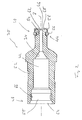
- a check valve insert 30 constructed according to the invention is shown, which in principle is used in a fuel metering pump, as described above with reference to FIGS Fig. 1 has been described, can be used. It should be noted in this context that, of course, at this Brennstoffdosierpumpe various variations can be provided, for example with respect to the drive for the pump piston 22, which can of course also be formed by an electric motor with an armature connected to the pump piston 22 and a surrounding coil assembly.
- the check valve insert 30 includes one in the direction of the longitudinal center axis A elongated insert body 52 having the two end portions 40 and 48.
- the insert body 52 At the first end region 40, ie the region with which the non-return valve insert is to be inserted into the housing 42, the insert body 52 is designed with a comparatively small outer dimension, which also substantially corresponds to the outer dimension of the pump piston 22, so that in the housing 22 through this passing and also the pumping chamber 20 providing opening can be provided with a substantially constant inner dimension.
- a circumferential groove 54 is provided on the insert body 52, in which the first sealing element 44 engages.
- This first sealing element 44 is not used as a separate O-ring-like sealing element in the circumferential groove 54, but is molded onto the end region 40 of the insert body 52. That is, in the manufacturing process of the sealing member 44, the end portion 40 of the insert body 52 is inserted into a corresponding injection mold or forms with its outer peripheral surface part of the injection mold, in which then the initially flowable material of the first sealing member 44 is injected.
- the upper and lower halves of the Fig. 2 with regard to this first sealing element 44 two different embodiments. In both embodiments, the sealing element 44 projects with a bead-like region 56 beyond the outer circumference of the insert body 52 at the first end region 40. In the in Fig. 2 shown on the bottom right, the sealing element 44 is shaped so that it substantially fills the entire circumferential groove 54, while at the in Fig. 2 is formed above right variant with essentially also beaded or rounded overall cross-section.
- a sleeve-like projection 58 is integrally formed on the end region 40 of the insert body 52.
- this projection 58 forms an integral part of the sealing element 44 and covers the end region 44 starting from the region of the sealing element 44 engaging in the circumferential groove 54.
- the sleeve-like projection 58 also covers an end face 60 of the insert body 52 first end portion 44 at least partially, but so that with a formed in this approach 58 the central opening 62 is the possibility that the liquid to be conveyed fuel can pass through the flow channel 32.
- the sealing element 44 or the projection 58 forms a stop plate 46, on which the pumping piston 22 can abut in its reciprocating motion. Since the entire sealing element 44 is constructed of elastic, for example, rubber-like material, not only is a sealing effect following the housing 42 obtained, but also a stop damping functionality is realized here.
- the second sealing element 50 is provided, which, as well as the first sealing member 44 to the insert body 52 is injected. Again, therefore, a solid, achieved by the curing material of the sealing member 50 and material-bonded composite.
- Fig. 2 above and below different cross-sectional geometries of the second sealing element 50. While in Fig. 2 is formed on the top left, the second sealing element 50 with substantially uniform density and only in the axially central region of a bead-like or hump-like increase is in Fig. 2 Lower left, the sealing element 50 is formed with a circular or generally curved cross-sectional geometry.
- sealing elements 44, 50 By molding or injection molding of the two sealing elements 44, 50 it is ensured that, when assembling a fuel metering pump, these sealing elements remain in a defined position, in particular due to their material-fit, ie adhesive, connection to the insert body 52 and thus ensure a secure sealing closure. This not only leads to higher reliability, but also basically simplifies the process of assembling a Brennstoffdosierpumpe.
Landscapes
- Engineering & Computer Science (AREA)
- General Engineering & Computer Science (AREA)
- Mechanical Engineering (AREA)
- Fuel-Injection Apparatus (AREA)
- Check Valves (AREA)
Abstract
Ein Rückschlagventileinsatz für eine Brennstoffdosierpumpe, insbesondere für ein Fahrzeugheizgerät, umfassend einen Einsatzkörper (52) mit einem durch diesen hindurch verlaufenden Strömungskanal (32), wobei der Einsatzkörper (52) in seinen beiden Endbereichen (40, 48) zur flüssigkeitsdichten Verbindung ausgebildet ist und zwischen seinen Endbereichen (40, 48) einen Ventilsitz (34) für einen Rückschlagventilkörper aufweist, ist dadurch gekennzeichnet, dass in wenigstens einem der Endbereiche (40, 48) der Einsatzkörper (52) ein an diesen angespritztes elastisches Dichtungselement (44, 50) trägt.A check valve insert for a fuel metering pump, in particular for a vehicle heater, comprising an insert body (52) having a flow channel (32) extending therethrough, wherein the insert body (52) is formed in its two end portions (40, 48) for fluid-tight connection and between its end regions (40, 48) has a valve seat (34) for a non-return valve body, characterized in that in at least one of the end regions (40, 48) the insert body (52) carries an elastic sealing element (44, 50) molded onto it.
Description
Die vorliegende Erfindung betrifft einen Rückschlagventileinsatz für eine Brennstoffdosierpumpe, insbesondere für ein Fahrzeugheizgerät, umfassend einen Einsatzkörper mit einem durch diesen hindurch verlaufenden Strömungskanal, wobei der Einsatzkörper in seinen beiden Endbereichen zur flüssigkeitsdichten Verbindung ausgebildet ist und zwischen seinen Endbereichen einen Ventilsitz für einen Rückschlagventilkörper aufweist.The present invention relates to a check valve insert for a fuel metering pump, in particular for a vehicle heater, comprising an insert body with a flow channel extending therethrough, wherein the insert body is formed in its two end portions for liquid-tight connection and between its end regions has a valve seat for a check valve body.
Eine Brennstoffdosierpumpe mit einem derartigen Rückschlagventileinsatz ist aus der
Das Rückschlagventil 26 ist mit einem Rückschlagventileinsatz 30 aufgebaut, der in Richtung der Längsmittenachse A langgestreckt ist und einen Strömungskanal 32 für den Brennstoff bereitstellt. Näherungsweise in seinem Längenmittenbereich bildet der Rückschlagventileinsatz 30 eine kegelstumpfartige Ventilsitzfläche 34 für einen als Kugel ausgebildeten Rückschlagventilkörper 36. Dieser ist durch eine Vorspannfeder 38 gegen die Ventilsitzfläche 34 vorgespannt.The
An einem ersten Endbereich 40 des Rückschlagventileinsatzes 30, welcher Endbereich 40 in ein auch die Pumpkammer 20 bereitstellendes Gehäuse 42 eingreift, ist eine Außenumfangsnut gebildet, in welche ein O-ringartiges Dichtungselement 44 eingesetzt ist. Ferner ist an der Stirnfläche dieses ersten Endbereichs 40 eine Anschlagplatte 46 vorgesehen, die, ebenso wie das Dichtungselement 44, aus elastischem Material aufgebaut ist und für eine Anschlagdämpfung sorgt, wenn der Pumpkolben 22 gegen den als Bewegungsanschlag wirksamen ersten Endbereich 40 stößt.At a
In einem zweiten Endbereich 48 ist der Aulassstutzen 28 in den Rückschlagventileinsatz 30 eingesetzt. Der Auslassstutzen 28 kann ebenfalls eine Außenumfangsnut aufweisen, in welche ein weiteres 0-ringartiges Dichtungselement 50 eingesetzt ist, so dass im zusammengefügten Zustand dieses Dichtungselement 50 an einer Innenumfangsfläche des Rückschlagventileinsatzes 30 anliegt. Durch die beiden Dichtungselemente 44, 50 wird eine flüssigkeitsdichte Verbindung des Rückschlagventileinsatzes 30 mit dem Gehäuse 22 einerseits und dem Auslassstutzen 28 andererseits erhalten.In a
Es ist die Aufgabe der vorliegenden Erfindung, einen Rückschlagventileinsatz für eine Brennstoffdosierpumpe vorzusehen, mit welchem bei erhöhter Betriebssicherheit ein vereinfachter Aufbau erzielt wird.It is the object of the present invention to provide a check valve insert for a fuel metering pump, with which a simplified construction is achieved with increased reliability.
Erfindungsgemäß wird diese Aufgabe gelöst durch einen Rückschlagventileinsatz für eine Brennstoffdosierpumpe, insbesondere für ein Fahrzeugheizgerät, umfassend einen Einsatzkörper mit einem durch diesen hindurch verlaufenden Strömungskanal, wobei der Einsatzkörper in seinen beiden Endbereichen zur flüssigkeitsdichten Verbindung ausgebildet ist und zwischen seinen Endbereichen einen Ventilsitz für einen Rückschlagventilkörper aufweist.According to the invention, this object is achieved by a check valve insert for a fuel metering pump, in particular for a vehicle heater, comprising an insert body with a flow channel extending therethrough, wherein the insert body is formed in its two end regions for liquid-tight connection and has a valve seat for a check valve body between its end portions.
Dabei ist weiter vorgesehen, dass in wenigstens einem der Endbereiche der Einsatzkörper ein an diesen angespritztes elastisches Dichtungselement trägt.It is further provided that in at least one of the end regions of the insert body carries a molded-on this elastic sealing element.
Durch das Vorsehen zumindest eines Dichtungselements nicht als separates Bauteil, das in eine Umfangnut eingesetzt wird, sondern als an den Einsatzkörper durch Anspritzen unmittelbar angeformtes und somit auch fest an diesem anhaftendes Bauteil, werden verschiedene Vorteile kombiniert. Zum einen wird eine Verbundbaugruppe geschaffen, die als solche in den Fertigungsprozess eingeführt werden kann und nicht durch vorherige Montage verschiedener Bauteile zusammengesetzt werden muss. Dies verringert die Gefahr von Fehlern bei der Montage und verringert ebenfalls die Gefahr, dass beim Zusammensetzen einer Brennstoffdosierpumpe durch ungewollte Verschiebungen ein derartiges Dichtungselement beschädigt wird bzw. in eine Positionierung gelangt, in welcher es eine Dichtungsfunktion nicht mehr korrekt erfüllen kann.By providing at least one sealing element not as a separate component which is inserted into a circumferential groove, but as directly molded onto the insert body by injection molding and thus also firmly adhering to this component, various advantages are combined. On the one hand, a composite assembly is created, which as such can be introduced into the manufacturing process and does not have to be assembled by previous assembly of various components. This reduces the risk of errors during assembly and also reduces the risk that when assembling a Brennstoffdosierpumpe by unintentional displacements such a sealing element is damaged or gets into a position in which it can no longer fulfill a sealing function correctly.
Beispielsweise kann vorgesehen sein, dass an einem ersten Endbereich ein erstes Dichtungselement den Einsatzkörper außen umgibt.For example, it can be provided that at a first end region, a first sealing element surrounds the insert body on the outside.
Um hier eine sehr stabile Halterung zu erlangen, wird weiter vorgeschlagen, dass das erste Dichtungselement in eine Außenumfangsnut des Einsatzkörpers eingeformt ist.In order to obtain a very stable support here, it is further proposed that the first sealing element is formed in an outer circumferential groove of the insert body.
Da ein derartiger Rückschlagventileinsatz auch als Bewegungsanschlag für einen Pumpkolben einer Brennstoffdosierpumpe wirksam sein kann, wird zur weiteren Vereinfachung des Gesamtaufbaus vorgeschlagen, dass das erste Dichtungselement mit einem hülsenartigen Ansatz eine Stirnfläche des Einsatzkörpers am ersten Endbereich wenigstens teilweise übergreift.Since such a check valve insert can also be effective as a movement stop for a pump piston of a fuel metering pump, it is proposed to further simplify the overall construction that the first sealing element with a sleeve-like projection at least partially overlaps an end face of the insert body at the first end region.
An einem zweiten Endbereich kann ein zweites Dichtungselement an einer Innenumfangsfläche des Einsatzkörpers vorgesehen sein.At a second end region, a second sealing element may be provided on an inner peripheral surface of the insert body.
Die vorliegende Erfindung betrifft ferner eine Brennstoffdosierpumpe, insbesondere für ein Fahrzeugheizgerät, welche mit einem erfindungsgemäß aufgebauten Rückschlagventileinsatz ausgebildet ist. Dieser Rückschlagventileinsatz kann, wie vorangehend bereits dargelegt, mit seinem ersten Endbereich einen Bewegungsanschlag für ein Pumporgan, also beispielsweise einen Pumpkolben, bilden, wobei durch Vorsehen eines die Stirnseite des Einsatzkörpers übergreifenden und integral mit dem ersten Dichtungselement angeformten elastischen Materials für eine Anschlagdämpfung gesorgt werden kann.The present invention further relates to a Brennstoffdosierpumpe, in particular for a vehicle heater, which is formed with a check valve constructed according to the invention. This check valve insert can, as already stated above, form with its first end region a movement stop for a pump element, that is, for example, a pump piston, whereby provision can be made for a stop damping by providing an elastic material which engages over the end face of the insert body and is integrally formed with the first seal element ,
Die vorliegende Erfindung wird nachfolgend mit Bezug auf die beiliegenden Figuren detailliert erläutert. Es zeigt:
- Fig. 1
- eine aus dem Stand der Technik bekannte Brennstoffdosierpumpe mit einem Rückschlagventileinsatz;
- Fig. 2
- eine Längsschnittansicht eines erfindungsgemäß aufgebauten Rückschlagventileinsatzes.
- Fig. 1
- a known from the prior art Brennstoffdosierpumpe with a check valve insert;
- Fig. 2
- a longitudinal sectional view of a inventively constructed check valve insert.
In
Der Rückschlagventileinsatz 30 umfasst einen in Richtung der Längsmittenachse A langgestreckten Einsatzkörper 52, welcher die beiden Endbereiche 40 und 48 aufweist. Am ersten Endbereich 40, also demjenigen Bereich, mit welchem der Rückschlagventileinsatz in das Gehäuse 42 einzuführen ist, ist der Einsatzkörper 52 mit vergleichsweise kleiner Außenabmessung ausgestaltet, welche im Wesentlichen auch der Außenabmessung des Pumpkolbens 22 entspricht, so dass in dem Gehäuse 22 eine durch dieses hindurchgehende und auch die Pumpkammer 20 bereitstellende Öffnung mit im Wesentlichen konstanter Innenabmessung vorgesehen sein kann. Am Endbereich 40 ist am Einsatzkörper 52 eine Umfangsnut 54 vorgesehen, in welche das erste Dichtungselement 44 eingreift. Dieses erste Dichtungselement 44 ist nicht als separates O-ringartiges Dichtungselement in die Umfangsnut 54 eingesetzt, sondern ist an den Endbereich 40 des Einsatzkörpers 52 angespritzt. D.h., beim Herstellungsvorgang des Dichtungselements 44 wird der Endbereich 40 des Einsatzkörpers 52 in eine entsprechende Spritzform eingesetzt bzw. bildet mit seiner Außenumfangsfläche einen Teil der Spritzform, in welche dann das zunächst noch fließfähige Material des ersten Dichtungselements 44 eingespritzt wird. Dabei zeigen die obere und die untere Hälfte der
Zusammen mit dem Dichtungselement 44 wird ein hülsenartiger Ansatz 58 an dem Endbereich 40 des Einsatzkörpers 52 angeformt. Dieser Ansatz 58 bildet also einen integralen Bestandteil des Dichtungselements 44 und überdeckt den Endbereich 44 ausgehend von dem in die Umfangsnut 54 eingreifenden Bereich des Dichtungselements 44. Insbesondere überdeckt der hülsenartige Ansatz 58 auch eine Stirnseite 60 des Einsatzkörpers 52 am ersten Endbereich 44 zumindest bereichsweise, jedoch so, dass mit einer in diesem Ansatz 58 gebildeten zentralen Öffnung 62 die Möglichkeit geschaffen ist, dass der zu fördernde flüssige Brennstoff durch den Strömungskanal 32 hindurchtreten kann. Mit dem die Stirnseite 60 überdeckenden Bereich bildet das Dichtungselement 44 bzw. der Ansatz 58 eine Anschlagplatte 46, an welcher der Pumpkolben 22 bei seiner Hin- und Herbewegung anstoßen kann. Da das gesamte Dichtungselement 44 aus elastischem, beispielsweise gummiartigem Material aufgebaut ist, wird also hier nicht nur eine Dichtwirkung im Anschluss an das Gehäuse 42 erhalten, sondern auch eine Anschlagdämpfungsfunktionalität realisiert.Together with the sealing
Im zweiten Endbereich 48 ist der Einsatzkörper 52 mit deutlich größerer Abmessung ausgebildet und bildet eine Einsatzöffnung 64 zur Aufnahme des Auslassstutzens 28. An einer beispielsweise im Wesentlichen zylindrischen Innenumfangsfläche 66 ist das zweite Dichtungselement 50 vorgesehen, das, ebenso wie das erste Dichtungselement 44 an den Einsatzkörper 52 angespritzt ist. Auch hier wird also ein fester, durch das aushärtende Material des Dichtungselements 50 auch materialschlüssiger Verbund erzielt. Man erkennt auch hier in
Durch das Anformen bzw. Anspritzen der beiden Dichtungselemente 44, 50 ist dafür gesorgt, dass beim Zusammensetzen einer Brennstoffdosierpumpe diese Dichtungselemente insbesondere auf Grund ihrer materialschlüssigen, also klebenden Anbindung an den Einsatzkörper 52 in definierter Positionierung verbleiben und somit für einen sicheren Dichtabschluss sorgen. Dies führt nicht nur zur höheren Betriebssicherheit, sondern vereinfacht grundsätzlich auch den Vorgang des Zusammensetzens einer Brennstoffdosierpumpe. By molding or injection molding of the two
Claims (7)
dadurch gekennzeichnet, dass in wenigstens einem der Endbereiche (40, 48) der Einsatzkörper (52) ein an diesen angespritztes elastisches Dichtungselement (44, 50) trägt.Check valve insert for a fuel metering pump, in particular for a vehicle heater, comprising an insert body (52) having a flow channel (32) extending therethrough, wherein the insert body (52) is formed in its two end regions (40, 48) for fluid-tight connection and between its End regions (40, 48) has a valve seat (34) for a return valve body,
characterized in that in at least one of the end regions (40, 48) of the insert body (52) carries a molded-on this elastic sealing element (44, 50).
dadurch gekennzeichnet, dass an einem ersten Endbereich (40) ein erstes Dichtungselement (44) den Einsatzkörper (52) außen umgibt.Check valve insert according to claim 1,
characterized in that at a first end region (40), a first sealing element (44) surrounds the insert body (52) on the outside.
dadurch gekennzeichnet, dass das erste Dichtungselement (44) in eine Außenumfangsnut (62) des Einsatzkörpers (52) eingeformt ist.Check valve insert according to claim 2,
characterized in that the first sealing element (44) is formed in an outer circumferential groove (62) of the insert body (52).
dadurch gekennzeichnet, dass das erste Dichtungselement (44) mit einem hülsenartigen Ansatz (58) eine Stirnfläche (60) des Einsatzkörpers (52) am ersten Endbereich (40) wenigstens teilweise übergreift.Check valve insert according to claim 2 or 3,
characterized in that the first sealing element (44) with a sleeve-like projection (58) at least partially overlaps an end face (60) of the insert body (52) at the first end region (40).
dadurch gekennzeichnet, dass an einem zweiten Endbereich (48) ein zweites Dichtungselement (50) an einer Innenumfangsfläche (66) des Einsatzkörpers (52) vorgesehen ist.Check valve insert according to one of claims 1 to 4,
characterized in that a second sealing element (50) is provided on an inner peripheral surface (66) of the insert body (52) at a second end region (48).
dadurch gekennzeichnet, dass der Rückschlagventileinsatz (30) mit seinem ersten Endbereich (44) einen Bewegungsanschlag für ein Pumporgan (22) bildet.Fuel metering pump according to claim 4 and claim 6,
characterized in that the check valve insert (30) forms with its first end region (44) a movement stop for a pump element (22).
Applications Claiming Priority (1)
| Application Number | Priority Date | Filing Date | Title |
|---|---|---|---|
| DE200710031033 DE102007031033A1 (en) | 2007-07-04 | 2007-07-04 | Check valve insert for a fuel metering pump |
Publications (3)
| Publication Number | Publication Date |
|---|---|
| EP2012009A2 true EP2012009A2 (en) | 2009-01-07 |
| EP2012009A3 EP2012009A3 (en) | 2010-10-27 |
| EP2012009B1 EP2012009B1 (en) | 2014-01-01 |
Family
ID=38542584
Family Applications (1)
| Application Number | Title | Priority Date | Filing Date |
|---|---|---|---|
| EP08010914.3A Active EP2012009B1 (en) | 2007-07-04 | 2008-06-16 | Return valve insert for a fuel dosing pump |
Country Status (2)
| Country | Link |
|---|---|
| EP (1) | EP2012009B1 (en) |
| DE (1) | DE102007031033A1 (en) |
Families Citing this family (5)
| Publication number | Priority date | Publication date | Assignee | Title |
|---|---|---|---|---|
| JP5949455B2 (en) | 2012-10-31 | 2016-07-06 | アイシン・エィ・ダブリュ株式会社 | Electromagnetic pump |
| CN104074702B (en) * | 2013-02-18 | 2017-03-01 | 中村英子 | The reductant metering pump of purifying internal combustion engine tail gas after-treatment system and assembly method |
| DE102015101068B4 (en) * | 2015-01-26 | 2021-04-22 | Eberspächer Climate Control Systems GmbH | Metering pump, in particular fuel metering pump for a vehicle heater |
| DE102015101067B4 (en) * | 2015-01-26 | 2021-04-22 | Eberspächer Climate Control Systems GmbH | Metering pump, in particular fuel metering pump for a vehicle heater |
| DE102015101066B4 (en) * | 2015-01-26 | 2024-03-14 | Eberspächer Climate Control Systems GmbH | Metering pump, in particular fuel metering pump for a vehicle heater |
Citations (1)
| Publication number | Priority date | Publication date | Assignee | Title |
|---|---|---|---|---|
| DE102004049171A1 (en) | 2004-10-08 | 2006-04-13 | J. Eberspächer GmbH & Co. KG | Metering pump, in particular Kraftstoffdosierpumpe for a vehicle heater or a reformer system |
Family Cites Families (2)
| Publication number | Priority date | Publication date | Assignee | Title |
|---|---|---|---|---|
| DE19902019A1 (en) * | 1999-01-20 | 2000-07-27 | Bosch Gmbh Robert | Piston pump |
| DE502005005266D1 (en) * | 2005-07-29 | 2008-10-16 | Truma Geraetetechnik Gmbh & Co | metering |
-
2007
- 2007-07-04 DE DE200710031033 patent/DE102007031033A1/en not_active Ceased
-
2008
- 2008-06-16 EP EP08010914.3A patent/EP2012009B1/en active Active
Patent Citations (1)
| Publication number | Priority date | Publication date | Assignee | Title |
|---|---|---|---|---|
| DE102004049171A1 (en) | 2004-10-08 | 2006-04-13 | J. Eberspächer GmbH & Co. KG | Metering pump, in particular Kraftstoffdosierpumpe for a vehicle heater or a reformer system |
Also Published As
| Publication number | Publication date |
|---|---|
| EP2012009B1 (en) | 2014-01-01 |
| DE102007031033A1 (en) | 2007-10-31 |
| EP2012009A3 (en) | 2010-10-27 |
Similar Documents
| Publication | Publication Date | Title |
|---|---|---|
| EP0734494B2 (en) | Reciprocating pump for pumping hydraulic fluid | |
| EP0199143B1 (en) | Push plunger pump for dispensing fluid media | |
| DE19818334A1 (en) | Readily assembled unitary safety valve used in e.g. an engine oil filter cartridge | |
| DE4022558A1 (en) | SEALING DEVICES FOR FLOW OPENINGS | |
| EP2606233B1 (en) | Valve of a piston pump with a closing body | |
| EP2012009B1 (en) | Return valve insert for a fuel dosing pump | |
| DE2427528A1 (en) | THROTTLE VALVE, IN PARTICULAR FOR A VEHICLE COOLING WATER CIRCUIT | |
| DE102008056245A1 (en) | thermostatic valve | |
| DE102007059239A1 (en) | Diaphragm, and reciprocating diaphragm pump | |
| EP2412417B1 (en) | Filter element and filter for filtering fluids | |
| EP0998342A1 (en) | Filter assembly | |
| DE102016220364A1 (en) | Electromagnetically actuated inlet valve and high-pressure pump with inlet valve | |
| DE102019217207A1 (en) | High pressure fuel pump for a fuel system of an internal combustion engine | |
| DE102011002427A1 (en) | Double check valve for e.g. preventing back-flow of reduction agent from storage tank of exhaust gas after treatment system of internal combustion engine of motor car, has disk-like elastic membrane provided with two slots | |
| DE102017205124A1 (en) | High-pressure fuel pump | |
| EP2884091B1 (en) | Fuel injector valve | |
| DE102007059240A1 (en) | Diaphragm pump for use as e.g. dosing pump in selective catalytic reduction exhaust gas cleaning system for diesel motor vehicle, has pump head enclosed between front sides of housing, so that head is held on housing | |
| DE102011089594A1 (en) | Intake valve for pump, has valve portion having upper region which is in contact with pin to guide pin, and lower region with sealing seat so that inlet valve is closed when sealing element rests against sealing seat | |
| EP1421308A1 (en) | Non-return valve for a pump | |
| EP1573196B1 (en) | Injector comprising a device for sealing an actuator unit, and sealing ring | |
| EP0169309B1 (en) | Valve device | |
| DE4133557A1 (en) | CONTROL DEVICE FOR STOPPING AN INTERNAL COMBUSTION ENGINE | |
| DE102006029823B3 (en) | Valve for regulation of the flow of a fluid medium through a heating system or a cooling system has axial pressure-relief slit | |
| DE10324303A1 (en) | Plug closure for aperture in automotive high-pressure fuel injection pump housing has threaded neck and smooth inner bore | |
| EP1504187A1 (en) | Injector for fuel injection |
Legal Events
| Date | Code | Title | Description |
|---|---|---|---|
| PUAI | Public reference made under article 153(3) epc to a published international application that has entered the european phase |
Free format text: ORIGINAL CODE: 0009012 |
|
| AK | Designated contracting states |
Kind code of ref document: A2 Designated state(s): AT BE BG CH CY CZ DE DK EE ES FI FR GB GR HR HU IE IS IT LI LT LU LV MC MT NL NO PL PT RO SE SI SK TR |
|
| AX | Request for extension of the european patent |
Extension state: AL BA MK RS |
|
| PUAL | Search report despatched |
Free format text: ORIGINAL CODE: 0009013 |
|
| AK | Designated contracting states |
Kind code of ref document: A3 Designated state(s): AT BE BG CH CY CZ DE DK EE ES FI FR GB GR HR HU IE IS IT LI LT LU LV MC MT NL NO PL PT RO SE SI SK TR |
|
| AX | Request for extension of the european patent |
Extension state: AL BA MK RS |
|
| 17P | Request for examination filed |
Effective date: 20110427 |
|
| AKX | Designation fees paid |
Designated state(s): AT BE BG CH CY CZ DE DK EE ES FI FR GB GR HR HU IE IS IT LI LT LU LV MC MT NL NO PL PT RO SE SI SK TR |
|
| RAP1 | Party data changed (applicant data changed or rights of an application transferred) |
Owner name: EBERSPAECHER CLIMATE CONTROL SYSTEMS GMBH & CO. KG |
|
| REG | Reference to a national code |
Ref country code: DE Ref legal event code: R079 Ref document number: 502008011142 Country of ref document: DE Free format text: PREVIOUS MAIN CLASS: F04B0013000000 Ipc: F16K0027020000 |
|
| GRAP | Despatch of communication of intention to grant a patent |
Free format text: ORIGINAL CODE: EPIDOSNIGR1 |
|
| RIC1 | Information provided on ipc code assigned before grant |
Ipc: F16J 15/14 20060101ALI20130902BHEP Ipc: F16K 27/02 20060101AFI20130902BHEP Ipc: F04B 53/16 20060101ALI20130902BHEP Ipc: F04B 53/10 20060101ALI20130902BHEP Ipc: F04B 53/22 20060101ALI20130902BHEP |
|
| INTG | Intention to grant announced |
Effective date: 20130924 |
|
| GRAS | Grant fee paid |
Free format text: ORIGINAL CODE: EPIDOSNIGR3 |
|
| GRAA | (expected) grant |
Free format text: ORIGINAL CODE: 0009210 |
|
| AK | Designated contracting states |
Kind code of ref document: B1 Designated state(s): AT BE BG CH CY CZ DE DK EE ES FI FR GB GR HR HU IE IS IT LI LT LU LV MC MT NL NO PL PT RO SE SI SK TR |
|
| REG | Reference to a national code |
Ref country code: GB Ref legal event code: FG4D Free format text: NOT ENGLISH |
|
| REG | Reference to a national code |
Ref country code: CH Ref legal event code: EP |
|
| REG | Reference to a national code |
Ref country code: IE Ref legal event code: FG4D Free format text: LANGUAGE OF EP DOCUMENT: GERMAN |
|
| REG | Reference to a national code |
Ref country code: DE Ref legal event code: R096 Ref document number: 502008011142 Country of ref document: DE Effective date: 20140213 |
|
| REG | Reference to a national code |
Ref country code: AT Ref legal event code: REF Ref document number: 647751 Country of ref document: AT Kind code of ref document: T Effective date: 20140215 |
|
| REG | Reference to a national code |
Ref country code: NL Ref legal event code: VDEP Effective date: 20140101 |
|
| REG | Reference to a national code |
Ref country code: LT Ref legal event code: MG4D |
|
| PG25 | Lapsed in a contracting state [announced via postgrant information from national office to epo] |
Ref country code: LT Free format text: LAPSE BECAUSE OF FAILURE TO SUBMIT A TRANSLATION OF THE DESCRIPTION OR TO PAY THE FEE WITHIN THE PRESCRIBED TIME-LIMIT Effective date: 20140101 Ref country code: IS Free format text: LAPSE BECAUSE OF FAILURE TO SUBMIT A TRANSLATION OF THE DESCRIPTION OR TO PAY THE FEE WITHIN THE PRESCRIBED TIME-LIMIT Effective date: 20140501 |
|
| PGFP | Annual fee paid to national office [announced via postgrant information from national office to epo] |
Ref country code: GB Payment date: 20140620 Year of fee payment: 7 |
|
| PG25 | Lapsed in a contracting state [announced via postgrant information from national office to epo] |
Ref country code: ES Free format text: LAPSE BECAUSE OF FAILURE TO SUBMIT A TRANSLATION OF THE DESCRIPTION OR TO PAY THE FEE WITHIN THE PRESCRIBED TIME-LIMIT Effective date: 20140101 Ref country code: FI Free format text: LAPSE BECAUSE OF FAILURE TO SUBMIT A TRANSLATION OF THE DESCRIPTION OR TO PAY THE FEE WITHIN THE PRESCRIBED TIME-LIMIT Effective date: 20140101 Ref country code: CY Free format text: LAPSE BECAUSE OF FAILURE TO SUBMIT A TRANSLATION OF THE DESCRIPTION OR TO PAY THE FEE WITHIN THE PRESCRIBED TIME-LIMIT Effective date: 20140101 Ref country code: PT Free format text: LAPSE BECAUSE OF FAILURE TO SUBMIT A TRANSLATION OF THE DESCRIPTION OR TO PAY THE FEE WITHIN THE PRESCRIBED TIME-LIMIT Effective date: 20140502 Ref country code: SE Free format text: LAPSE BECAUSE OF FAILURE TO SUBMIT A TRANSLATION OF THE DESCRIPTION OR TO PAY THE FEE WITHIN THE PRESCRIBED TIME-LIMIT Effective date: 20140101 Ref country code: NL Free format text: LAPSE BECAUSE OF FAILURE TO SUBMIT A TRANSLATION OF THE DESCRIPTION OR TO PAY THE FEE WITHIN THE PRESCRIBED TIME-LIMIT Effective date: 20140101 |
|
| PG25 | Lapsed in a contracting state [announced via postgrant information from national office to epo] |
Ref country code: HR Free format text: LAPSE BECAUSE OF FAILURE TO SUBMIT A TRANSLATION OF THE DESCRIPTION OR TO PAY THE FEE WITHIN THE PRESCRIBED TIME-LIMIT Effective date: 20140101 Ref country code: LV Free format text: LAPSE BECAUSE OF FAILURE TO SUBMIT A TRANSLATION OF THE DESCRIPTION OR TO PAY THE FEE WITHIN THE PRESCRIBED TIME-LIMIT Effective date: 20140101 |
|
| REG | Reference to a national code |
Ref country code: DE Ref legal event code: R082 Ref document number: 502008011142 Country of ref document: DE Representative=s name: RUTTENSPERGER LACHNIT TROSSIN GOMOLL PATENT- U, DE Ref country code: DE Ref legal event code: R082 Ref document number: 502008011142 Country of ref document: DE Representative=s name: RUTTENSPERGER LACHNIT TROSSIN GOMOLL, PATENT- , DE |
|
| REG | Reference to a national code |
Ref country code: DE Ref legal event code: R097 Ref document number: 502008011142 Country of ref document: DE |
|
| PG25 | Lapsed in a contracting state [announced via postgrant information from national office to epo] |
Ref country code: DK Free format text: LAPSE BECAUSE OF FAILURE TO SUBMIT A TRANSLATION OF THE DESCRIPTION OR TO PAY THE FEE WITHIN THE PRESCRIBED TIME-LIMIT Effective date: 20140101 Ref country code: RO Free format text: LAPSE BECAUSE OF FAILURE TO SUBMIT A TRANSLATION OF THE DESCRIPTION OR TO PAY THE FEE WITHIN THE PRESCRIBED TIME-LIMIT Effective date: 20140101 Ref country code: EE Free format text: LAPSE BECAUSE OF FAILURE TO SUBMIT A TRANSLATION OF THE DESCRIPTION OR TO PAY THE FEE WITHIN THE PRESCRIBED TIME-LIMIT Effective date: 20140101 Ref country code: CZ Free format text: LAPSE BECAUSE OF FAILURE TO SUBMIT A TRANSLATION OF THE DESCRIPTION OR TO PAY THE FEE WITHIN THE PRESCRIBED TIME-LIMIT Effective date: 20140101 |
|
| PLBE | No opposition filed within time limit |
Free format text: ORIGINAL CODE: 0009261 |
|
| STAA | Information on the status of an ep patent application or granted ep patent |
Free format text: STATUS: NO OPPOSITION FILED WITHIN TIME LIMIT |
|
| PG25 | Lapsed in a contracting state [announced via postgrant information from national office to epo] |
Ref country code: SK Free format text: LAPSE BECAUSE OF FAILURE TO SUBMIT A TRANSLATION OF THE DESCRIPTION OR TO PAY THE FEE WITHIN THE PRESCRIBED TIME-LIMIT Effective date: 20140101 Ref country code: PL Free format text: LAPSE BECAUSE OF FAILURE TO SUBMIT A TRANSLATION OF THE DESCRIPTION OR TO PAY THE FEE WITHIN THE PRESCRIBED TIME-LIMIT Effective date: 20140101 |
|
| PGFP | Annual fee paid to national office [announced via postgrant information from national office to epo] |
Ref country code: FR Payment date: 20140617 Year of fee payment: 7 |
|
| 26N | No opposition filed |
Effective date: 20141002 |
|
| REG | Reference to a national code |
Ref country code: DE Ref legal event code: R097 Ref document number: 502008011142 Country of ref document: DE Effective date: 20141002 |
|
| PG25 | Lapsed in a contracting state [announced via postgrant information from national office to epo] |
Ref country code: LU Free format text: LAPSE BECAUSE OF FAILURE TO SUBMIT A TRANSLATION OF THE DESCRIPTION OR TO PAY THE FEE WITHIN THE PRESCRIBED TIME-LIMIT Effective date: 20140616 Ref country code: MC Free format text: LAPSE BECAUSE OF FAILURE TO SUBMIT A TRANSLATION OF THE DESCRIPTION OR TO PAY THE FEE WITHIN THE PRESCRIBED TIME-LIMIT Effective date: 20140101 |
|
| REG | Reference to a national code |
Ref country code: CH Ref legal event code: PL |
|
| REG | Reference to a national code |
Ref country code: IE Ref legal event code: MM4A |
|
| PG25 | Lapsed in a contracting state [announced via postgrant information from national office to epo] |
Ref country code: CH Free format text: LAPSE BECAUSE OF NON-PAYMENT OF DUE FEES Effective date: 20140630 Ref country code: IE Free format text: LAPSE BECAUSE OF NON-PAYMENT OF DUE FEES Effective date: 20140616 Ref country code: LI Free format text: LAPSE BECAUSE OF NON-PAYMENT OF DUE FEES Effective date: 20140630 |
|
| PG25 | Lapsed in a contracting state [announced via postgrant information from national office to epo] |
Ref country code: SI Free format text: LAPSE BECAUSE OF FAILURE TO SUBMIT A TRANSLATION OF THE DESCRIPTION OR TO PAY THE FEE WITHIN THE PRESCRIBED TIME-LIMIT Effective date: 20140101 |
|
| REG | Reference to a national code |
Ref country code: AT Ref legal event code: MM01 Ref document number: 647751 Country of ref document: AT Kind code of ref document: T Effective date: 20140616 |
|
| PG25 | Lapsed in a contracting state [announced via postgrant information from national office to epo] |
Ref country code: AT Free format text: LAPSE BECAUSE OF NON-PAYMENT OF DUE FEES Effective date: 20140616 |
|
| GBPC | Gb: european patent ceased through non-payment of renewal fee |
Effective date: 20150616 |
|
| PG25 | Lapsed in a contracting state [announced via postgrant information from national office to epo] |
Ref country code: MT Free format text: LAPSE BECAUSE OF FAILURE TO SUBMIT A TRANSLATION OF THE DESCRIPTION OR TO PAY THE FEE WITHIN THE PRESCRIBED TIME-LIMIT Effective date: 20140101 |
|
| REG | Reference to a national code |
Ref country code: FR Ref legal event code: ST Effective date: 20160229 |
|
| PG25 | Lapsed in a contracting state [announced via postgrant information from national office to epo] |
Ref country code: NO Free format text: LAPSE BECAUSE OF FAILURE TO SUBMIT A TRANSLATION OF THE DESCRIPTION OR TO PAY THE FEE WITHIN THE PRESCRIBED TIME-LIMIT Effective date: 20140401 Ref country code: GB Free format text: LAPSE BECAUSE OF NON-PAYMENT OF DUE FEES Effective date: 20150616 |
|
| PG25 | Lapsed in a contracting state [announced via postgrant information from national office to epo] |
Ref country code: FR Free format text: LAPSE BECAUSE OF NON-PAYMENT OF DUE FEES Effective date: 20150630 Ref country code: BG Free format text: LAPSE BECAUSE OF FAILURE TO SUBMIT A TRANSLATION OF THE DESCRIPTION OR TO PAY THE FEE WITHIN THE PRESCRIBED TIME-LIMIT Effective date: 20140101 |
|
| PG25 | Lapsed in a contracting state [announced via postgrant information from national office to epo] |
Ref country code: IT Free format text: LAPSE BECAUSE OF FAILURE TO SUBMIT A TRANSLATION OF THE DESCRIPTION OR TO PAY THE FEE WITHIN THE PRESCRIBED TIME-LIMIT Effective date: 20140101 Ref country code: GR Free format text: LAPSE BECAUSE OF FAILURE TO SUBMIT A TRANSLATION OF THE DESCRIPTION OR TO PAY THE FEE WITHIN THE PRESCRIBED TIME-LIMIT Effective date: 20140402 |
|
| PG25 | Lapsed in a contracting state [announced via postgrant information from national office to epo] |
Ref country code: HU Free format text: LAPSE BECAUSE OF FAILURE TO SUBMIT A TRANSLATION OF THE DESCRIPTION OR TO PAY THE FEE WITHIN THE PRESCRIBED TIME-LIMIT; INVALID AB INITIO Effective date: 20080616 Ref country code: BE Free format text: LAPSE BECAUSE OF FAILURE TO SUBMIT A TRANSLATION OF THE DESCRIPTION OR TO PAY THE FEE WITHIN THE PRESCRIBED TIME-LIMIT Effective date: 20140630 Ref country code: TR Free format text: LAPSE BECAUSE OF FAILURE TO SUBMIT A TRANSLATION OF THE DESCRIPTION OR TO PAY THE FEE WITHIN THE PRESCRIBED TIME-LIMIT Effective date: 20140101 |
|
| REG | Reference to a national code |
Ref country code: DE Ref legal event code: R082 Ref document number: 502008011142 Country of ref document: DE Representative=s name: RUTTENSPERGER LACHNIT TROSSIN GOMOLL, PATENT- , DE Ref country code: DE Ref legal event code: R081 Ref document number: 502008011142 Country of ref document: DE Owner name: EBERSPAECHER CLIMATE CONTROL SYSTEMS GMBH, DE Free format text: FORMER OWNER: EBERSPAECHER CLIMATE CONTROL SYSTEMS GMBH & CO. KG, 73730 ESSLINGEN, DE |
|
| PGFP | Annual fee paid to national office [announced via postgrant information from national office to epo] |
Ref country code: DE Payment date: 20250630 Year of fee payment: 18 |