EP2012047A2 - Système de fermeture pour véhicules, de préférence pour véhicules automobiles - Google Patents
Système de fermeture pour véhicules, de préférence pour véhicules automobiles Download PDFInfo
- Publication number
- EP2012047A2 EP2012047A2 EP08011571A EP08011571A EP2012047A2 EP 2012047 A2 EP2012047 A2 EP 2012047A2 EP 08011571 A EP08011571 A EP 08011571A EP 08011571 A EP08011571 A EP 08011571A EP 2012047 A2 EP2012047 A2 EP 2012047A2
- Authority
- EP
- European Patent Office
- Prior art keywords
- locking system
- leg
- vehicles according
- pinion
- flat slide
- Prior art date
- Legal status (The legal status is an assumption and is not a legal conclusion. Google has not performed a legal analysis and makes no representation as to the accuracy of the status listed.)
- Granted
Links
Images


Classifications
-
- E—FIXED CONSTRUCTIONS
- E05—LOCKS; KEYS; WINDOW OR DOOR FITTINGS; SAFES
- E05B—LOCKS; ACCESSORIES THEREFOR; HANDCUFFS
- E05B81/00—Power-actuated vehicle locks
- E05B81/24—Power-actuated vehicle locks characterised by constructional features of the actuator or the power transmission
- E05B81/25—Actuators mounted separately from the lock and controlling the lock functions through mechanical connections
-
- B—PERFORMING OPERATIONS; TRANSPORTING
- B60—VEHICLES IN GENERAL
- B60J—WINDOWS, WINDSCREENS, NON-FIXED ROOFS, DOORS, OR SIMILAR DEVICES FOR VEHICLES; REMOVABLE EXTERNAL PROTECTIVE COVERINGS SPECIALLY ADAPTED FOR VEHICLES
- B60J7/00—Non-fixed roofs; Roofs with movable panels, e.g. rotary sunroofs
- B60J7/185—Locking arrangements
- B60J7/1851—Locking arrangements for locking the foldable soft- or hard-top to the windshield header
-
- Y—GENERAL TAGGING OF NEW TECHNOLOGICAL DEVELOPMENTS; GENERAL TAGGING OF CROSS-SECTIONAL TECHNOLOGIES SPANNING OVER SEVERAL SECTIONS OF THE IPC; TECHNICAL SUBJECTS COVERED BY FORMER USPC CROSS-REFERENCE ART COLLECTIONS [XRACs] AND DIGESTS
- Y10—TECHNICAL SUBJECTS COVERED BY FORMER USPC
- Y10T—TECHNICAL SUBJECTS COVERED BY FORMER US CLASSIFICATION
- Y10T74/00—Machine element or mechanism
- Y10T74/18—Mechanical movements
- Y10T74/18056—Rotary to or from reciprocating or oscillating
- Y10T74/18088—Rack and pinion type
- Y10T74/18096—Shifting rack
-
- Y—GENERAL TAGGING OF NEW TECHNOLOGICAL DEVELOPMENTS; GENERAL TAGGING OF CROSS-SECTIONAL TECHNOLOGIES SPANNING OVER SEVERAL SECTIONS OF THE IPC; TECHNICAL SUBJECTS COVERED BY FORMER USPC CROSS-REFERENCE ART COLLECTIONS [XRACs] AND DIGESTS
- Y10—TECHNICAL SUBJECTS COVERED BY FORMER USPC
- Y10T—TECHNICAL SUBJECTS COVERED BY FORMER US CLASSIFICATION
- Y10T74/00—Machine element or mechanism
- Y10T74/18—Mechanical movements
- Y10T74/18568—Reciprocating or oscillating to or from alternating rotary
- Y10T74/1876—Reciprocating or oscillating to or from alternating rotary including inertia device
- Y10T74/18768—Reciprocating or oscillating to or from alternating rotary including inertia device with rack and pinion
- Y10T74/18776—Rectilinear rack
Definitions
- the invention relates to a closure system for vehicles, preferably for motor vehicles, according to the preamble of claim 1.
- a drive device for a movable part on a vehicle body in which at least one pressure-resistant axially movable drive cable is displaced via a drive pinion in the axial direction.
- the rotational movement of the drive pinion is transmitted via a toothing on a coil surrounding the drive cable in an axial direction of movement.
- the drive cable is passed at least partially through tubular cable guides.
- an additional support element is provided, which supports the movement to be transmitted from the drive pinion to the drive cable.
- the support element is U-shaped, wherein in the region of the legs of the support element particular start-up angle and surfaces are provided. With these surfaces, a safe and quiet operation is to be achieved.
- the entire unit is additionally housed in a separate housing.
- the DE 38 32 681 C1 shows a locking unit, which serves to operate a sliding and / or lifting roof.
- a drive device preferably a drive pinion
- the sliding / lifting roof is actuated by means of a pressure-resistant guided in guide tubes drive cable.
- the drive cable with its guide tubes and the drive pinion is encapsulated by a holding device / housing made of plastic. This encapsulation part is simultaneously designed as a receptacle for the drive pinion.
- the drive pinion meshes with the helix of the drive cable, wherein in the engagement region, the drive cable must be supported by the guide tubes and the encapsulation part forms the housing.
- the invention has for its object to provide a cost-locking system, which is a particularly flat, and easy-to-install unit, wherein the actuating forces of the closure system are in equilibrium to each other.
- the closure unit is preferably installed in a roof unit. Between the closure unit and the closure elements, for example closure hooks, a transmission element, for example a linkage, is provided for transmitting the closing movement.
- a transmission element for example a linkage
- the locking system is also suitable for mounting in other areas of the vehicle, in addition to rod for transmission and Bowden cables can be used.
- the lengths of the U-shaped legs make it possible to realize stops within the closure unit.
- the ends of individual legs abut, for example, against an inner wall of the closure housing.
- the leg ends can be prevented by the web of the U-shaped legs at a further translational movement.
- the ends of the legs are prevented with the racks on reaching the pinion by a lack of outlet of the racks on a further movement.
- These ends may be provided with extensions that are directed as stops on the respective opposite rack. In this case, these extensions encounter corresponding displacement of the flat slide on the pinion, whereby a further displacement of the flat slide can not be done.
- An additional variant is the use of a closure housing which is open only on one side and from which a flat slide emerges only on one side.
- the second flat slide is designed in this case without a holder for fastening transmission or actuators. He shifts in the same way as in the system described above, but is moved and guided exclusively within the shutter housing.
- the closure housing and the housing cover can be made of plastic.
- the arranged inside the closure housing lateral guides can be made small, since only small forces must be supported.
- the lateral guides are provided at best for introducing a bias on the flat slide.
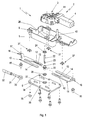
- FIG. 1 the locking system is shown as an exploded view with all the essential components.
- the drive unit 2 is positioned relative to one another via a receiving bore and a fixing pin provided on the inside of the closure housing 5, wherein the drive unit 2 is pushed onto the fixing pin 40 with the receiving bore.
- the gear 3 driving the shutter 1 is positioned flush with an opening of the shutter housing 5 in the mounted state.
- This opening has on the opposite side of the transmission housing 3 of the closure housing 5, an upper bearing receptacle 26, in which an upper bearing bush 24 is introduced.
- the closure housing 5 is closed by means of the housing cover 6 and screws 35 firmly together.
- a lower bearing bush 25 is inserted into a lower bearing receptacle 27 in the housing cover 6, starting from the closure housing 5.
- the axial extension of a pinion 20 is received and stored in both bearing bushes 24, 25 on both sides.
- the two bearing bushes 24, 25 are made of a plain bearing material such as brass or a slide bearing suitable plastic.
- the pinion 20 is guided over its lateral tooth surfaces on the flange surfaces of the bearing blocks 24, 25.
- a hexagon socket 21 On the drive unit 2 side facing the pinion 20 in its axial extension a hexagon socket 21, in which the external hexagon 23 of a drive shaft 22 is received.
- This drive shaft 22 connects the pinion 20 with the output gear of the transmission, wherein the hexagon socket 21 can extend over the entire axial dimension of the pinion 20.
- the toothing of the pinion 20 meshes with two parallel racks 13 of two U-shaped flat slide 10, 11, wherein the racks 10, 11 are each arranged on the inside of one of the U-shaped legs.
- the racks 13 carrying legs 12 are arranged opposite each other, wherein the pinion 20 is located in the middle between the legs 12.
- the racks 13 and the legs 14 are mutually supported so that transverse to the legs 13, 14 occurring forces are compensated.
- each flat slide 10, 11 cranked holder 16 At the connecting webs of the two U-shaped legs 13, 14 are at each flat slide 10, 11 cranked holder 16 in the form of a right angle attached, wherein the crank is formed in the direction of the drive unit 2.
- These cranked holders 16 are eccentrically positioned the longitudinal extent of the U-shaped flat slide 10, 11 at the webs and each have a bore 17 for receiving a cylindrical flange of a ball joint pin 15.
- a ball joint head 30 On the ball joint pin 15, a ball joint head 30 is arranged, which is held by means of a fuse together with the ball joint pin 15 in its position.
- the ball joint head 30 has on one side of its outer diameter an outer diameter reducing taper.
- a tube 32 is pushed onto the cylindrical shaft 31, which tube is deformed in the regions of the constrictions of the cylindrical shaft 31 in these tapers. In this way, a permanent, positive connection between the ball joint head 30 on the one hand and the tube 32 on the other hand is created.
- the closure housing 5 is sealed on its open side with a housing cover 6 by means of the screws 35 which protrude through bores 36 of the housing cover 6.
- a lower bearing bush 25 is installed in a lower bearing seat 27 of the housing cover 6.
- guides 38 in the closure housing 5 inside serve to guide and fix the two flat slides 10, 11 during the opening or closing operation of the closure unit 1.
- the guides 38 may be integrally formed from the housing cover 6 or incorporated as a separate component in corresponding receiving openings of the housing cover 6.
- support plates 37 are inserted into the mounting holes 8 of the closure housing 5 during assembly of the closure unit. These support plates 37 are necessary when the closure housing 5 is made of plastic, for example, and serve to ensure that the walls of the fastening openings 8 are not deformed or damaged during the screwing of the closure housing 5. Next will 37 allows the mounting distance of the fasteners and defined Anschraub mechanism by dimensioning the support plates.
- FIG. 2 is a cross section through the drive shaft 22 and through the pinion 20 in the assembled state of the closure unit 1 shown.
- the flat slide 10, 11 are mounted between the closure housing 5 and the housing cover 6, wherein the racks 13 of the flat slide 10, 11 are in engagement with the pinion 20.
- the pinion 20 is guided with its upper cylindrical extension in the upper bearing bush 24 and with its lower cylindrical extension in the lower bearing bush 25. From the side of the drive unit 2 protrudes as a connecting element between the pinion 20 and the drive unit 2, a drive shaft 22 to approximately central position in the pinion 20 into it.
- the drive shaft 22 opposite free area of the hexagon socket 21 of the pinion 20 is connected through the opening of the lower bearing receptacle 27 to the outside. Through this opening, if necessary, a crank with an external hexagon can be inserted and thus the pinion 20 and the entire closure 1 can be opened or closed by manual operation. This is always the case when there is no sufficient supply voltage for the electric drive of the closure 1 available. This manual operation thus represents an emergency / unlocking or a hand-operated unlocking.
- FIG. 3 shows a view of the flat slide 10, 11 in the extended slide position.
- the shutter 1 between the roof and the upper roof frame of the windshield is closed / locked.
- To open the flat slide 10, 11 by rotation of the pinion 20th pushed together.
- By the displacement 16 articulated push / pull rods 32 are moved to the cranked holders, which are connected at their closure unit 1 opposite sides with necessary to lock the roof closure elements.
- the cranked holder 16 are arranged offset on the web side of the U-shaped flat slide 10, 11 to the side of the racks 13. In assembled position, the cranked holder 16 are in alignment in the same longitudinal plane as the pinion 20, so that the effect of the pulling or pushing movement can be introduced sidearm neutral in the push / pull rods 32.
- the two U-shaped legs 12, 14 of the flat slide 10, 11 have substantially the same width, wherein a leg 12 is provided on its side facing the opposite leg 14 with a toothing.
- This leg 12 is at least partially formed as a rack 13, wherein the length of the toothing of the sliding movement of the push / pull rods 32 is dependent.
- Both U-shaped, interlocking flat slide 10, 11 are provided with a rack 13, wherein the legs 12 with the racks 13 are in constant mesh with the pinion 20.
- the backs of the legs 12 are on the respective inner sides of the straight legs 14 of the other U-shaped flat slide 10, 11.
- Each leg 12 with a rack 13 is thus clamped and guided between the pinion 20 and the straight leg 14 of the other flat slide 10, 11.
- the system of these intermeshing U-shaped legs 12, 14 constitutes a self-contained system in terms of force. If a toothed rack 13 wishes to lift off the pinion 20 on one side of the pinion 20, the toothed rack 13 rests against the inside of the straight leg 14 of the other end Flat slide 10, 11 from, in turn, on the bridge of the U-shaped flat slide 10, 11 and on the rack 13 of this flat slide 10, 11 is supported on the pinion 20.
- Both flat slide 10, 11 are identical components that form the interlocking and mutually supporting closure unit 2 by mirror image mounting.
- the legs 12, 14 of the U-shaped flat slide 10, 11 are not only supported, but also led together.
- the flat slide 10 11 further guides in the passage areas of the housing openings 39 and in the central position of the closure housing 5 in the region of the pinion 20 are provided. These guides are dimensioned with their dimensions so that a lateral tilting of the flat slide 10, 11 is reliably prevented.
- 39 lateral guides 38 for the flat slide 10, 11 mounted on the inside of the housing cover 6 in the areas between the central guides and the guides in the housing openings. Among other things, these lateral guides serve to position the flat slides 10, 11 relative to one another during assembly and to hold them on the housing cover 6.
- These lateral guides 38 protrude as narrow webs from the housing cover 6 and can exert lateral forces on these similar inclinations in the direction of the flat slide 10, 11 similar to a leaf spring. Further, these transverse forces tension the flat slide 10, 11 to each other, which avoids possible rattling noises and tolerances of the slide 10, 11, the pinion 20 and / or the housing 5 can be compensated.
- the ends of the racks 13 are designed as a short and flat region corresponding to the width of the rack 13.
- the U-shaped recess between the legs 12, 14 of the width of the racks 13 is adjusted.
- the ends of the flat slide 10, 11 are received in these U-shaped recesses and the flat slide 10, 11 thus additionally guided to each other and supported.
- the end of the leg 12 with the rack 13 to the web of the opposite U-shaped flat slide 10, 11 encounter, thus between the two slides 10, 11 thus a stop is formed.
- This broadening is step-shaped and provided in the transition regions 28 with radii.
- the geometric shape of the stepped transition region 28 may be designed so that when pushed together flat slides 10, 11, the step-shaped transition regions 28 as stops on the pinion 20 come to rest.
- the transition region 28 of the cylindrical shape of the pinion 20 may be adjusted.
Landscapes
- Engineering & Computer Science (AREA)
- Mechanical Engineering (AREA)
- Transmission Devices (AREA)
- Lock And Its Accessories (AREA)
Applications Claiming Priority (1)
| Application Number | Priority Date | Filing Date | Title |
|---|---|---|---|
| DE102007030851A DE102007030851A1 (de) | 2007-07-03 | 2007-07-03 | Verschlusssystem für Fahrzeuge, vorzugsweise für Kraftfahrzeuge |
Publications (3)
| Publication Number | Publication Date |
|---|---|
| EP2012047A2 true EP2012047A2 (fr) | 2009-01-07 |
| EP2012047A3 EP2012047A3 (fr) | 2013-06-05 |
| EP2012047B1 EP2012047B1 (fr) | 2015-08-12 |
Family
ID=39809887
Family Applications (1)
| Application Number | Title | Priority Date | Filing Date |
|---|---|---|---|
| EP08011571.0A Ceased EP2012047B1 (fr) | 2007-07-03 | 2008-06-26 | Système de fermeture pour véhicules, de préférence pour véhicules automobiles |
Country Status (3)
| Country | Link |
|---|---|
| US (1) | US8082812B2 (fr) |
| EP (1) | EP2012047B1 (fr) |
| DE (1) | DE102007030851A1 (fr) |
Cited By (4)
| Publication number | Priority date | Publication date | Assignee | Title |
|---|---|---|---|---|
| DE102009004038A1 (de) * | 2009-01-08 | 2010-09-16 | Webasto Ag | Kopplungsstange |
| DE102009052782A1 (de) * | 2009-11-11 | 2011-05-12 | Dr. Ing. H.C. F. Porsche Aktiengesellschaft | Schließvorrichtung |
| DE102013109930A1 (de) | 2013-09-10 | 2015-03-12 | BROSE SCHLIEßSYSTEME GMBH & CO. KG | Antriebsanordnung zur motorischen Verstellung einer Abdeckklappenanordnung |
| FR3036329A1 (fr) * | 2015-05-21 | 2016-11-25 | Peugeot Citroen Automobiles Sa | Commande d’un systeme de deverrouillage |
Families Citing this family (10)
| Publication number | Priority date | Publication date | Assignee | Title |
|---|---|---|---|---|
| DE102010055635A1 (de) * | 2010-12-22 | 2012-06-28 | Volkswagen Ag | Antriebseinheit, insbesondere für ein Dachöffnungssystem eines Fahrzeuges |
| DE102013013199B4 (de) * | 2013-04-18 | 2017-11-16 | Deon Group AG | Elektromotorischer Möbelantrieb |
| WO2018033868A1 (fr) * | 2016-08-16 | 2018-02-22 | Marangoni Meccanica S.P.A. | Guide télescopique bidirectionnel |
| DE102017206449B4 (de) | 2017-04-13 | 2022-07-07 | Dometic Sweden Ab | Wohnwagenfenster und Öffnungsmechanismus dafür |
| DE202017106376U1 (de) * | 2017-04-13 | 2017-10-30 | Dometic Sweden Ab | Wohnwagenfenster und Öffnungsmechanismus dafür |
| US10683038B2 (en) | 2017-08-24 | 2020-06-16 | Dometic Sweden Ab | Caravan window with ventilation |
| US11007972B2 (en) * | 2017-09-22 | 2021-05-18 | GM Global Technology Operations LLC | Multi-pull latch and lock systems for compartment closure assemblies of motor vehicles |
| DE102017124282A1 (de) * | 2017-10-18 | 2019-04-18 | Kiekert Ag | Aufstellvorrichtung für eine Kraftfahrzeugtür |
| DE102018212739A1 (de) * | 2018-07-31 | 2020-02-06 | Brose Fahrzeugteile Gmbh & Co. Kommanditgesellschaft, Coburg | Elektromotorisch verstellbare Lenkvorrichtung |
| KR101976721B1 (ko) * | 2018-12-10 | 2019-05-09 | 엘아이지넥스원 주식회사 | 가리개 장치 |
Citations (2)
| Publication number | Priority date | Publication date | Assignee | Title |
|---|---|---|---|---|
| DE3809949A1 (de) | 1988-03-24 | 1989-10-05 | Webasto Ag Fahrzeugtechnik | Vorrichtung zum antrieb eines drucksteif gefuehrten antriebskabels |
| DE3832681C1 (fr) | 1988-09-27 | 1989-10-26 | Webasto Ag Fahrzeugtechnik, 8035 Gauting, De |
Family Cites Families (9)
| Publication number | Priority date | Publication date | Assignee | Title |
|---|---|---|---|---|
| US823341A (en) | 1905-08-25 | 1906-06-12 | Fred Nevell Livingston | Mechanical movement. |
| US1213800A (en) * | 1916-06-28 | 1917-01-23 | Weber Joseph | Lifting-jack and pulling device. |
| DE3706849A1 (de) * | 1987-03-03 | 1988-09-15 | Sachs Systemtechnik Gmbh | Stelleinrichtung, insbesondere fuer eine kraftfahrzeugreibungskupplung |
| DE19538798A1 (de) | 1995-10-18 | 1997-04-24 | Schwab Christian Dipl Designer | Zahnstangengetriebe |
| US6283392B1 (en) | 2000-01-18 | 2001-09-04 | Brunswick Corporation | Fishing reel with oscillating assembly for distributing line evenly on a spool |
| DE10057760B4 (de) * | 2000-11-22 | 2004-08-12 | Bos Gmbh & Co. Kg | Fensterrollo mit Zentriereinrichtung für den Zugstab |
| US7559585B2 (en) * | 2004-08-20 | 2009-07-14 | Wilhelm Karmann Gmbh | Support frame for header latch assembly |
| US7377529B2 (en) | 2004-11-30 | 2008-05-27 | Trw Automotive U.S. Llc | Active roll control system for a vehicle suspension system |
| DE102005029559B4 (de) * | 2005-06-23 | 2007-05-03 | Bos Gmbh & Co. Kg | Heckfensterrollo mit vollständiger Schlitzabdeckung durch das Auszugsprofil |
-
2007
- 2007-07-03 DE DE102007030851A patent/DE102007030851A1/de not_active Ceased
-
2008
- 2008-06-26 EP EP08011571.0A patent/EP2012047B1/fr not_active Ceased
- 2008-07-02 US US12/166,735 patent/US8082812B2/en not_active Expired - Fee Related
Patent Citations (2)
| Publication number | Priority date | Publication date | Assignee | Title |
|---|---|---|---|---|
| DE3809949A1 (de) | 1988-03-24 | 1989-10-05 | Webasto Ag Fahrzeugtechnik | Vorrichtung zum antrieb eines drucksteif gefuehrten antriebskabels |
| DE3832681C1 (fr) | 1988-09-27 | 1989-10-26 | Webasto Ag Fahrzeugtechnik, 8035 Gauting, De |
Cited By (5)
| Publication number | Priority date | Publication date | Assignee | Title |
|---|---|---|---|---|
| DE102009004038A1 (de) * | 2009-01-08 | 2010-09-16 | Webasto Ag | Kopplungsstange |
| DE102009004038B4 (de) * | 2009-01-08 | 2012-11-15 | Webasto Ag | Kopplungsstange |
| DE102009052782A1 (de) * | 2009-11-11 | 2011-05-12 | Dr. Ing. H.C. F. Porsche Aktiengesellschaft | Schließvorrichtung |
| DE102013109930A1 (de) | 2013-09-10 | 2015-03-12 | BROSE SCHLIEßSYSTEME GMBH & CO. KG | Antriebsanordnung zur motorischen Verstellung einer Abdeckklappenanordnung |
| FR3036329A1 (fr) * | 2015-05-21 | 2016-11-25 | Peugeot Citroen Automobiles Sa | Commande d’un systeme de deverrouillage |
Also Published As
| Publication number | Publication date |
|---|---|
| US20090007707A1 (en) | 2009-01-08 |
| EP2012047B1 (fr) | 2015-08-12 |
| DE102007030851A1 (de) | 2009-02-19 |
| EP2012047A3 (fr) | 2013-06-05 |
| US8082812B2 (en) | 2011-12-27 |
Similar Documents
| Publication | Publication Date | Title |
|---|---|---|
| EP2012047B1 (fr) | Système de fermeture pour véhicules, de préférence pour véhicules automobiles | |
| EP2075395B1 (fr) | Actionneur pour un dispositif à fermeture assistée d'une serrure de véhicule | |
| EP1645458B1 (fr) | Réducteur et siège de véhicule comportant un tel réducteur | |
| EP2423022B1 (fr) | Mécanisme d'entraînement muni d'un actionnement d'urgence | |
| DE102005063402B4 (de) | Getriebe und Fahrzeugsitz mit einem solchen Getriebe | |
| EP3826885B1 (fr) | Siège de véhicule | |
| WO2002039852A1 (fr) | Mecanisme de commande a moteur electrique | |
| WO2019081081A1 (fr) | Colonne de direction pour véhicule automobile | |
| EP2346715A1 (fr) | Dispositif de support pour entraînement linéaire | |
| DE20311032U1 (de) | Antriebsvorrichtung | |
| DE102023131832A1 (de) | Vorrichtung zum Verschließen und Freigeben eines Energieladeanschlusses eines Kraftfahrzeugs | |
| DE60121299T2 (de) | Lenkeinrichtung mit variablem Winkelverhältnis | |
| DE10048224A1 (de) | Verriegelungseinheit für einen Teleskopausleger eines Krans | |
| DE102019128563A1 (de) | Elektromechanischer Parksperrenaktuator | |
| EP1862628A1 (fr) | Système de déplacement d'un véhicule à moteur pour déplacement d'un élément de fermeture pour fermer une ouverture d'une carosserie d'un véhicule à moteur | |
| EP3957813B1 (fr) | Dispositif d'entraînement et porte coulissante | |
| DE19847016A1 (de) | Vorrichtung zum Bewegen eines Teils, insbesondere in einem Kraftfahrzeug, mit einem Verstellmechanismus | |
| EP3947881B1 (fr) | Entraînement de porte coulissante d'un véhicule automobile | |
| DE102014002455B4 (de) | Schwenkantrieb zur Verstellung verstellbarer Karosserieteile, z.B. Luftleitbleche und/oder Spoiler od. dgl., eines Kraftfahrzeugs | |
| DE102017118470A1 (de) | Betätigungsvorrichtung für Funktionselemente und Verfahren zur Betätigung von Funktionselementen | |
| DE102011007298A1 (de) | Motor-Getriebe-Baugruppe für ein Rollosystem sowie Rollosystem | |
| DE10240552A1 (de) | Kraftfahrzeug Türschloß | |
| DE2163534A1 (de) | Vorrichtung zum bewegen von einrichtungen, wie z.b. fensterscheiben, schiebedaecher, wischelementen und dergl., an kraftfahrzeugen | |
| DE102005048659B4 (de) | Verstellmechanismus | |
| DE102005047978B3 (de) | Antriebsgehäuse für ein bewegbares Fahrzeugteil |
Legal Events
| Date | Code | Title | Description |
|---|---|---|---|
| PUAI | Public reference made under article 153(3) epc to a published international application that has entered the european phase |
Free format text: ORIGINAL CODE: 0009012 |
|
| AK | Designated contracting states |
Kind code of ref document: A2 Designated state(s): AT BE BG CH CY CZ DE DK EE ES FI FR GB GR HR HU IE IS IT LI LT LU LV MC MT NL NO PL PT RO SE SI SK TR |
|
| AX | Request for extension of the european patent |
Extension state: AL BA MK RS |
|
| RAP1 | Party data changed (applicant data changed or rights of an application transferred) |
Owner name: AUDI AG |
|
| PUAL | Search report despatched |
Free format text: ORIGINAL CODE: 0009013 |
|
| AK | Designated contracting states |
Kind code of ref document: A3 Designated state(s): AT BE BG CH CY CZ DE DK EE ES FI FR GB GR HR HU IE IS IT LI LT LU LV MC MT NL NO PL PT RO SE SI SK TR |
|
| AX | Request for extension of the european patent |
Extension state: AL BA MK RS |
|
| RIC1 | Information provided on ipc code assigned before grant |
Ipc: F16H 19/00 20060101AFI20130426BHEP Ipc: E05B 65/12 20060101ALI20130426BHEP Ipc: B60J 7/185 20060101ALI20130426BHEP |
|
| 17P | Request for examination filed |
Effective date: 20131205 |
|
| RBV | Designated contracting states (corrected) |
Designated state(s): AT BE BG CH CY CZ DE DK EE ES FI FR GB GR HR HU IE IS IT LI LT LU LV MC MT NL NO PL PT RO SE SI SK TR |
|
| AKX | Designation fees paid |
Designated state(s): DE FR GB IT |
|
| GRAP | Despatch of communication of intention to grant a patent |
Free format text: ORIGINAL CODE: EPIDOSNIGR1 |
|
| RIC1 | Information provided on ipc code assigned before grant |
Ipc: B60J 7/185 20060101ALI20150331BHEP Ipc: F16H 19/00 20060101AFI20150331BHEP Ipc: E05B 81/24 20140101ALI20150331BHEP |
|
| INTG | Intention to grant announced |
Effective date: 20150428 |
|
| GRAS | Grant fee paid |
Free format text: ORIGINAL CODE: EPIDOSNIGR3 |
|
| GRAA | (expected) grant |
Free format text: ORIGINAL CODE: 0009210 |
|
| AK | Designated contracting states |
Kind code of ref document: B1 Designated state(s): DE FR GB IT |
|
| REG | Reference to a national code |
Ref country code: GB Ref legal event code: FG4D Free format text: NOT ENGLISH |
|
| REG | Reference to a national code |
Ref country code: DE Ref legal event code: R096 Ref document number: 502008013248 Country of ref document: DE |
|
| PG25 | Lapsed in a contracting state [announced via postgrant information from national office to epo] |
Ref country code: IT Free format text: LAPSE BECAUSE OF FAILURE TO SUBMIT A TRANSLATION OF THE DESCRIPTION OR TO PAY THE FEE WITHIN THE PRESCRIBED TIME-LIMIT Effective date: 20150812 |
|
| REG | Reference to a national code |
Ref country code: DE Ref legal event code: R097 Ref document number: 502008013248 Country of ref document: DE |
|
| PLBE | No opposition filed within time limit |
Free format text: ORIGINAL CODE: 0009261 |
|
| STAA | Information on the status of an ep patent application or granted ep patent |
Free format text: STATUS: NO OPPOSITION FILED WITHIN TIME LIMIT |
|
| REG | Reference to a national code |
Ref country code: FR Ref legal event code: PLFP Year of fee payment: 9 |
|
| 26N | No opposition filed |
Effective date: 20160513 |
|
| REG | Reference to a national code |
Ref country code: FR Ref legal event code: PLFP Year of fee payment: 10 |
|
| REG | Reference to a national code |
Ref country code: DE Ref legal event code: R084 Ref document number: 502008013248 Country of ref document: DE |
|
| REG | Reference to a national code |
Ref country code: FR Ref legal event code: PLFP Year of fee payment: 11 |
|
| PGFP | Annual fee paid to national office [announced via postgrant information from national office to epo] |
Ref country code: ES Payment date: 20190801 Year of fee payment: 12 |
|
| PGFP | Annual fee paid to national office [announced via postgrant information from national office to epo] |
Ref country code: FR Payment date: 20200620 Year of fee payment: 13 |
|
| PGFP | Annual fee paid to national office [announced via postgrant information from national office to epo] |
Ref country code: GB Payment date: 20200620 Year of fee payment: 13 |
|
| REG | Reference to a national code |
Ref country code: DE Ref legal event code: R119 Ref document number: 502008013248 Country of ref document: DE |
|
| PG25 | Lapsed in a contracting state [announced via postgrant information from national office to epo] |
Ref country code: DE Free format text: LAPSE BECAUSE OF NON-PAYMENT OF DUE FEES Effective date: 20210101 |
|
| GBPC | Gb: european patent ceased through non-payment of renewal fee |
Effective date: 20210626 |
|
| PG25 | Lapsed in a contracting state [announced via postgrant information from national office to epo] |
Ref country code: GB Free format text: LAPSE BECAUSE OF NON-PAYMENT OF DUE FEES Effective date: 20210626 |
|
| PG25 | Lapsed in a contracting state [announced via postgrant information from national office to epo] |
Ref country code: FR Free format text: LAPSE BECAUSE OF NON-PAYMENT OF DUE FEES Effective date: 20210630 |