EP2012061A1 - Deflektor für rückwärtigen Teil der Brennkammer, damit ausgestattete Brennkammer und mit dieser ausgestatteter Gasturbinenmotor - Google Patents
Deflektor für rückwärtigen Teil der Brennkammer, damit ausgestattete Brennkammer und mit dieser ausgestatteter Gasturbinenmotor Download PDFInfo
- Publication number
- EP2012061A1 EP2012061A1 EP08159737A EP08159737A EP2012061A1 EP 2012061 A1 EP2012061 A1 EP 2012061A1 EP 08159737 A EP08159737 A EP 08159737A EP 08159737 A EP08159737 A EP 08159737A EP 2012061 A1 EP2012061 A1 EP 2012061A1
- Authority
- EP
- European Patent Office
- Prior art keywords
- combustion chamber
- edge
- chamber
- deflector
- edges
- Prior art date
- Legal status (The legal status is an assumption and is not a legal conclusion. Google has not performed a legal analysis and makes no representation as to the accuracy of the status listed.)
- Granted
Links
Images


Classifications
-
- F—MECHANICAL ENGINEERING; LIGHTING; HEATING; WEAPONS; BLASTING
- F23—COMBUSTION APPARATUS; COMBUSTION PROCESSES
- F23R—GENERATING COMBUSTION PRODUCTS OF HIGH PRESSURE OR HIGH VELOCITY, e.g. GAS-TURBINE COMBUSTION CHAMBERS
- F23R3/00—Continuous combustion chambers using liquid or gaseous fuel
- F23R3/002—Wall structures
-
- F—MECHANICAL ENGINEERING; LIGHTING; HEATING; WEAPONS; BLASTING
- F23—COMBUSTION APPARATUS; COMBUSTION PROCESSES
- F23R—GENERATING COMBUSTION PRODUCTS OF HIGH PRESSURE OR HIGH VELOCITY, e.g. GAS-TURBINE COMBUSTION CHAMBERS
- F23R3/00—Continuous combustion chambers using liquid or gaseous fuel
- F23R3/02—Continuous combustion chambers using liquid or gaseous fuel characterised by the air-flow or gas-flow configuration
- F23R3/04—Air inlet arrangements
- F23R3/10—Air inlet arrangements for primary air
-
- F—MECHANICAL ENGINEERING; LIGHTING; HEATING; WEAPONS; BLASTING
- F23—COMBUSTION APPARATUS; COMBUSTION PROCESSES
- F23R—GENERATING COMBUSTION PRODUCTS OF HIGH PRESSURE OR HIGH VELOCITY, e.g. GAS-TURBINE COMBUSTION CHAMBERS
- F23R3/00—Continuous combustion chambers using liquid or gaseous fuel
- F23R3/42—Continuous combustion chambers using liquid or gaseous fuel characterised by the arrangement or form of the flame tubes or combustion chambers
- F23R3/50—Combustion chambers comprising an annular flame tube within an annular casing
Definitions
- the present invention relates to the technical field of combustion chambers for gas turbine engine. It is particularly aimed at the bedroom floor. Finally, it relates to a gas turbine engine such as a turbojet engine equipped with such a combustion chamber.
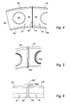
- a divergent conventional combustion chamber is illustrated on the figure 1 , which is an axial section showing a half of the combustion chamber, the other half of which is deduced by symmetry with respect to the axis of the motor (not shown).
- the combustion chamber 110 is housed in a diffusion chamber 130 which is an annular space defined between an outer casing 132 and an inner casing 134, into which is introduced an oxidant, ambient air, compressed coming upstream of a compressor (no represented) via an annular diffusion duct 136.
- This diverging combustion chamber 110 comprises two concentric walls: one external 112 and the other internal 114, which are coaxial and substantially conical. The walls widen from upstream to downstream. The outer 112 and inner 114 walls of the combustion chamber 110 are connected together, upstream of the combustion chamber by a chamber bottom 116.
- the chamber bottom 116 is a frustoconical annular piece, which extends between two substantially transverse planes flaring from downstream to upstream.
- the chamber bottom 116 is connected to each of the two outer wall 112 and inner 114 of the combustion chamber 110.
- the chamber bottom 116 has a small taper. It is equipped with injection systems 118 through which pass injectors 120 which introduce fuel to the upstream end of the combustion chamber 110 where the combustion reactions take place.
- deflectors 122 are interposed between the fireplace and the walls of the chamber bottom.
- These deflectors 122 are substantially flat plates brazed to the chamber bottom 116 with a central opening 122a for the passage of the injection system. They comprise two lateral walls 122b 122c along the radial edges, turned towards the wall of the chamber bottom and two tongues 122e 122f for guiding air along the transverse edges facing the hearth and leaving a space with the walls 114 and 112 , internally respectively external, of the chamber.
- the baffles are cooled by the impacts of cooling air jets entering the combustion chamber 110 through cooling orifices 124 drilled in the chamber bottom 116.
- the air forming these jets, flowing from the upstream downstream, is guided by chamber shrouds 126, passes through the chamber bottom 116 through the cooling orifices, and impinges on the upstream face of the deflectors 122.
- the air is then guided radially inwards and outside the focus to initiate the cooling film of the walls 114 and 112 respectively.
- This guidance along the baffles is provided by the side walls oriented radially. These walls also have a sealing function. By being in contact or by ensuring a minimum clearance with the chamber bottom, They prevent air from coming in between two adjacent baffles, enter the home and disrupt combustion. These disturbances affect pollution and should be avoided. Indeed, the pollutant discharge performance, CO and CHx are likely to be degraded by the parasitic introduction of this cold air particularly at engine idling speed where the game is more important.
- convergent combustion chambers In the context of other engine architectures where the flow of gas is generally convergent between the compressor outlet and the inlet of the turbine, there are so-called convergent combustion chambers, the outer and inner walls of the combustion chamber are inclined by widening from downstream to upstream, and not from upstream to downstream as with the first combustion chambers mentioned above, said divergent. These convergent combustion chambers may have a larger cone angle than the cone angle of the diverging combustion chambers.
- Such a large inclination of the combustion chamber affects the taper of the chamber bottom and the position of the baffles relative to the chamber bottom.
- a combustion chamber is partially illustrated at the figure 2 , in axial section. In this figure appear an axial direction 100 parallel to the axis of the turbojet, the main direction 200 of the combustion chamber 210, and the angle ⁇ between these two axes 100, 200. Due to the significant inclination of the chamber 200, the chamber bottom 216 has a larger taper angle than for a chamber bottom of convergent combustion. When not only the inclination of the chamber bottom 216 is important, but also the injectors 220 are present in reduced number and / or the combustion chamber 210 has a small diameter, it affects the distance between the chamber bottom and flat deflectors.
- the geometry of the chamber bottom can also make difficult the necessary adjustments and tolerances between the bottom wall of the chamber and the baffles.
- the optimal operation of the room is no longer ensured.
- the variation of the clearance between the baffles on the one hand and the baffles and the bottom chamber on the other hand is large enough so that the solution using side walls along the radial edges of the deflectors is no longer satisfactory.
- a combustion chamber bottom deflector of a gas turbine engine comprising a wall portion with an opening for the passage of an injection system of the combustion chamber, two edges longitudinal and two transverse edges, characterized in that at least one of the longitudinal edges comprises a joint cover forming a housing along said edge for an attached tongue or the edge of an adjacent baffle so as to seal the joint between said edge and the edge of an adjacent baffle.
- the solution of the invention is thus to seal the space between the baffles so as not to be dependent on the geometry of the combustion chamber and the chamber bottom in particular and to be able to absorb the dimensional variations related to the operation of the baffle. the room between idle speed and full throttle.
- the present invention also relates to a combustion chamber of an annular gas turbine engine comprising an outer wall, an inner wall, a wall connecting the two walls and constituting a chamber bottom, and a plurality of deflectors according to the invention. with a portion of wall parallel to the chamber bottom, reported in the bottom.
- the baffles are all identical and are mounted on the periphery of the chamber bottom being fixed by the flanges of the openings for the injection systems.
- the joint cover formed by the tongue 10d1 of each of the baffles covers the edge 10'c adjacent deflector 10 'over a width sufficient to accommodate variations in expansion of the combustion chamber.
- Each housing 10d10, 10'd10 is arranged to retain the edge 10c, 10'c of the adjacent baffle such that leaks between two adjacent baffles are reduced or completely eliminated whatever the engine speed.
- the Figures 7, 8 and 9 represent a first variant with a throat seal cover that improves the sealing compared to the previous solution.
- the deflectors 20, 20 ' are seen with a planar wall 20a, 20'a, a central opening 20b, 20'b two longitudinal edges 20c, 20'c and 20d, 20'd and two rounded and curved transverse edges 20e, 20'. e and 20f, 20'f.
- the longitudinal edge 20d comprises a tongue 20d1 parallel to the wall of the baffle and providing a housing 20d10g in the form of a groove. This groove is arranged to cooperate with the edge 20'c of the adjacent deflector.
- the edge 20'c forms a rear recess to engage in the groove 20d10g.
- the game is enough to allow the expansion of the combustion chamber during different engine speeds while maintaining a sealing contact between the edge 20'c and the sides of the groove 20d10g.
- baffles may all be identical or alternate: one with covers joined on both edges and the other with simple edges cooperating with the grooves of the edges with joint covers.
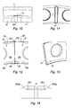
- the Figures 10 and 11 show an improvement between the baffles and the chamber bottom.
- the chamber floor 2 comprises a radial groove 2r in the area where the joint cover of the junction of the baffles is placed. This groove 2 'allows to provide a sufficient gap, when the covers joined are of a greater thickness than the clearance between the flat portion 20a of the baffle and the wall of the chamber bottom.
- baffles 30, 30 ' with a flat wall 30a, 30'a, a central opening 30b, 30'b, two longitudinal edges 30c, 30'c and 30d, 30'd and two transverse edges curved and curved 30e, 30e and 30f, 30'f.
- the two longitudinal edges 30c, 30d; 30'c, 30'd each comprise a tab 30c1, 30d1; 30'c1, 30'd1 parallel to the wall of the baffle and providing a housing 30c10g and 30d10g, 30'c10g, 304d10g shaped throat.
- These grooves are arranged to cooperate with a metal insert tab 31.
- the tongue is housed in the adjacent grooves 30d10g and 30'cl0g. The clearance is sufficient to allow the expansion of the combustion chamber during different engine speeds while maintaining a sealing contact between the edge 20'c and the sides of the groove 20d10g.
Landscapes
- Engineering & Computer Science (AREA)
- Chemical & Material Sciences (AREA)
- Combustion & Propulsion (AREA)
- Mechanical Engineering (AREA)
- General Engineering & Computer Science (AREA)
- Gasket Seals (AREA)
- Combustion Methods Of Internal-Combustion Engines (AREA)
- Turbine Rotor Nozzle Sealing (AREA)
- Supercharger (AREA)
Applications Claiming Priority (1)
| Application Number | Priority Date | Filing Date | Title |
|---|---|---|---|
| FR0704869A FR2918444B1 (fr) | 2007-07-05 | 2007-07-05 | Deflecteur de fond de chambre, chambre de combustion le comportant et moteur a turbine a gaz en etant equipe |
Publications (3)
| Publication Number | Publication Date |
|---|---|
| EP2012061A1 true EP2012061A1 (de) | 2009-01-07 |
| EP2012061B1 EP2012061B1 (de) | 2016-12-07 |
| EP2012061B2 EP2012061B2 (de) | 2020-06-17 |
Family
ID=39267949
Family Applications (1)
| Application Number | Title | Priority Date | Filing Date |
|---|---|---|---|
| EP08159737.9A Active EP2012061B2 (de) | 2007-07-05 | 2008-07-04 | Brennkammer eines Gasturbinentriebwerks |
Country Status (5)
| Country | Link |
|---|---|
| US (2) | US20090019856A1 (de) |
| EP (1) | EP2012061B2 (de) |
| CA (1) | CA2636659C (de) |
| FR (1) | FR2918444B1 (de) |
| RU (1) | RU2498162C2 (de) |
Cited By (5)
| Publication number | Priority date | Publication date | Assignee | Title |
|---|---|---|---|---|
| FR2943403A1 (fr) * | 2009-03-17 | 2010-09-24 | Snecma | Chambre de combustion de turbomachine comprenant des moyens ameliores d'alimentation en air |
| EP2463583A1 (de) * | 2010-12-06 | 2012-06-13 | Alstom Technology Ltd | Gasturbine sowie Verfahren zum Rekonditionieren einer solchen Gasturbine |
| FR3064050A1 (fr) * | 2017-03-14 | 2018-09-21 | Safran Aircraft Engines | Chambre de combustion d'une turbomachine |
| FR3078384A1 (fr) * | 2018-02-28 | 2019-08-30 | Safran Aircraft Engines | Chambre de combustion a fond de chambre double |
| US11300296B2 (en) | 2018-06-04 | 2022-04-12 | Safran Aircraft Engines | Combustion chamber of a turbomachine |
Families Citing this family (15)
| Publication number | Priority date | Publication date | Assignee | Title |
|---|---|---|---|---|
| US10174949B2 (en) * | 2013-02-08 | 2019-01-08 | United Technologies Corporation | Gas turbine engine combustor liner assembly with convergent hyperbolic profile |
| US8984896B2 (en) * | 2013-08-23 | 2015-03-24 | Pratt & Whitney Canada Corp. | Interlocking combustor heat shield panels |
| US9534784B2 (en) * | 2013-08-23 | 2017-01-03 | Pratt & Whitney Canada Corp. | Asymmetric combustor heat shield panels |
| GB201501817D0 (en) * | 2015-02-04 | 2015-03-18 | Rolls Royce Plc | A combustion chamber and a combustion chamber segment |
| US10041679B2 (en) * | 2015-06-24 | 2018-08-07 | Delavan Inc | Combustion systems |
| US10739001B2 (en) | 2017-02-14 | 2020-08-11 | Raytheon Technologies Corporation | Combustor liner panel shell interface for a gas turbine engine combustor |
| US10677462B2 (en) | 2017-02-23 | 2020-06-09 | Raytheon Technologies Corporation | Combustor liner panel end rail angled cooling interface passage for a gas turbine engine combustor |
| US10823411B2 (en) | 2017-02-23 | 2020-11-03 | Raytheon Technologies Corporation | Combustor liner panel end rail cooling enhancement features for a gas turbine engine combustor |
| US10830434B2 (en) | 2017-02-23 | 2020-11-10 | Raytheon Technologies Corporation | Combustor liner panel end rail with curved interface passage for a gas turbine engine combustor |
| US10718521B2 (en) | 2017-02-23 | 2020-07-21 | Raytheon Technologies Corporation | Combustor liner panel end rail cooling interface passage for a gas turbine engine combustor |
| US10941937B2 (en) | 2017-03-20 | 2021-03-09 | Raytheon Technologies Corporation | Combustor liner with gasket for gas turbine engine |
| US11408609B2 (en) * | 2018-10-26 | 2022-08-09 | Collins Engine Nozzles, Inc. | Combustor dome tiles |
| US11143108B2 (en) | 2019-03-07 | 2021-10-12 | Pratt & Whitney Canada Corp. | Annular heat shield assembly for combustor |
| US11226099B2 (en) * | 2019-10-11 | 2022-01-18 | Rolls-Royce Corporation | Combustor liner for a gas turbine engine with ceramic matrix composite components |
| US12209750B2 (en) * | 2023-02-14 | 2025-01-28 | Collins Engine Nozzles, Inc. | Line replaceable fuel injector panels with single hatch installation |
Citations (8)
| Publication number | Priority date | Publication date | Assignee | Title |
|---|---|---|---|---|
| JPS5915728A (ja) * | 1982-07-19 | 1984-01-26 | Central Res Inst Of Electric Power Ind | 高熱曝露壁面の熱遮断構造 |
| US4843825A (en) * | 1988-05-16 | 1989-07-04 | United Technologies Corporation | Combustor dome heat shield |
| GB2247522A (en) * | 1990-09-01 | 1992-03-04 | Rolls Royce Plc | Gas turbine engine combustor |
| EP0521687A1 (de) * | 1991-07-01 | 1993-01-07 | General Electric Company | Aufbau eines Brennkammerdomes |
| EP0724119A2 (de) * | 1995-01-26 | 1996-07-31 | General Electric Company | Stirnwand für eine Gasturbinenbrennkammer |
| US5799491A (en) * | 1995-02-23 | 1998-09-01 | Rolls-Royce Plc | Arrangement of heat resistant tiles for a gas turbine engine combustor |
| EP1271059A2 (de) * | 2001-06-28 | 2003-01-02 | General Electric Company | Verfahren und Systeme zur Kühlung von Gasturbinenbrennkammern |
| EP1528343A1 (de) * | 2003-10-27 | 2005-05-04 | Siemens Aktiengesellschaft | Keramischer Hitzeschildstein mit eingebetteten Verstärkungselementen zur Auskleidung einer Gasturbinenbrennkammerwand |
Family Cites Families (11)
| Publication number | Priority date | Publication date | Assignee | Title |
|---|---|---|---|---|
| US4480436A (en) * | 1972-12-19 | 1984-11-06 | General Electric Company | Combustion chamber construction |
| US4180974A (en) * | 1977-10-31 | 1980-01-01 | General Electric Company | Combustor dome sleeve |
| SU1753783A1 (ru) * | 1990-02-27 | 1996-06-10 | Моторостроительное конструкторское бюро | Камера сгорания газотурбинного двигателя |
| EP0591565B1 (de) * | 1992-10-05 | 1996-01-24 | Asea Brown Boveri Ag | Leitschaufeleinhängung für axialdurchströmte Turbomaschine |
| US6164074A (en) * | 1997-12-12 | 2000-12-26 | United Technologies Corporation | Combustor bulkhead with improved cooling and air recirculation zone |
| EP1118806A1 (de) * | 2000-01-20 | 2001-07-25 | Siemens Aktiengesellschaft | Thermisch belastbare Wand und Verfahren zur Abdichtung eines Spaltes in einer thermisch belasteten Wand |
| US7121095B2 (en) * | 2003-08-11 | 2006-10-17 | General Electric Company | Combustor dome assembly of a gas turbine engine having improved deflector plates |
| JP4476152B2 (ja) * | 2005-04-01 | 2010-06-09 | 三菱重工業株式会社 | ガスタービン燃焼器 |
| FR2897417A1 (fr) * | 2006-02-10 | 2007-08-17 | Snecma Sa | Chambre de combustion annulaire d'une turbomachine |
| FR2914399B1 (fr) * | 2007-03-27 | 2009-10-02 | Snecma Sa | Carenage pour fond de chambre de combustion. |
| FR2918443B1 (fr) * | 2007-07-04 | 2009-10-30 | Snecma Sa | Chambre de combustion comportant des deflecteurs de protection thermique de fond de chambre et moteur a turbine a gaz en etant equipe |
-
2007
- 2007-07-05 FR FR0704869A patent/FR2918444B1/fr active Active
-
2008
- 2008-07-01 US US12/165,995 patent/US20090019856A1/en not_active Abandoned
- 2008-07-02 CA CA2636659A patent/CA2636659C/fr active Active
- 2008-07-04 RU RU2008127426/06A patent/RU2498162C2/ru active
- 2008-07-04 EP EP08159737.9A patent/EP2012061B2/de active Active
-
2013
- 2013-08-02 US US13/958,000 patent/US8683806B2/en active Active
Patent Citations (8)
| Publication number | Priority date | Publication date | Assignee | Title |
|---|---|---|---|---|
| JPS5915728A (ja) * | 1982-07-19 | 1984-01-26 | Central Res Inst Of Electric Power Ind | 高熱曝露壁面の熱遮断構造 |
| US4843825A (en) * | 1988-05-16 | 1989-07-04 | United Technologies Corporation | Combustor dome heat shield |
| GB2247522A (en) * | 1990-09-01 | 1992-03-04 | Rolls Royce Plc | Gas turbine engine combustor |
| EP0521687A1 (de) * | 1991-07-01 | 1993-01-07 | General Electric Company | Aufbau eines Brennkammerdomes |
| EP0724119A2 (de) * | 1995-01-26 | 1996-07-31 | General Electric Company | Stirnwand für eine Gasturbinenbrennkammer |
| US5799491A (en) * | 1995-02-23 | 1998-09-01 | Rolls-Royce Plc | Arrangement of heat resistant tiles for a gas turbine engine combustor |
| EP1271059A2 (de) * | 2001-06-28 | 2003-01-02 | General Electric Company | Verfahren und Systeme zur Kühlung von Gasturbinenbrennkammern |
| EP1528343A1 (de) * | 2003-10-27 | 2005-05-04 | Siemens Aktiengesellschaft | Keramischer Hitzeschildstein mit eingebetteten Verstärkungselementen zur Auskleidung einer Gasturbinenbrennkammerwand |
Cited By (11)
| Publication number | Priority date | Publication date | Assignee | Title |
|---|---|---|---|---|
| FR2943403A1 (fr) * | 2009-03-17 | 2010-09-24 | Snecma | Chambre de combustion de turbomachine comprenant des moyens ameliores d'alimentation en air |
| US9127841B2 (en) | 2009-03-17 | 2015-09-08 | Snecma | Turbomachine combustion chamber comprising improved means of air supply |
| EP2463583A1 (de) * | 2010-12-06 | 2012-06-13 | Alstom Technology Ltd | Gasturbine sowie Verfahren zum Rekonditionieren einer solchen Gasturbine |
| CH704185A1 (de) * | 2010-12-06 | 2012-06-15 | Alstom Technology Ltd | Gasturbine sowie verfahren zum rekonditionieren einer solchen gasturbine. |
| AU2011253595B2 (en) * | 2010-12-06 | 2015-07-16 | General Electric Technology Gmbh | Gas turbine and method for reconditioning such a gas turbine |
| FR3064050A1 (fr) * | 2017-03-14 | 2018-09-21 | Safran Aircraft Engines | Chambre de combustion d'une turbomachine |
| US10684018B2 (en) | 2017-03-14 | 2020-06-16 | Safran Aircraft Engines | Combustion chamber of a turbine engine |
| FR3078384A1 (fr) * | 2018-02-28 | 2019-08-30 | Safran Aircraft Engines | Chambre de combustion a fond de chambre double |
| WO2019166745A1 (fr) * | 2018-02-28 | 2019-09-06 | Safran Aircraft Engines | Chambre de combustion a fond de chambre double |
| US11248793B2 (en) | 2018-02-28 | 2022-02-15 | Safran Aircraft Engines | Combustion chamber having a double chamber bottom |
| US11300296B2 (en) | 2018-06-04 | 2022-04-12 | Safran Aircraft Engines | Combustion chamber of a turbomachine |
Also Published As
| Publication number | Publication date |
|---|---|
| CA2636659A1 (fr) | 2009-01-05 |
| US8683806B2 (en) | 2014-04-01 |
| US20130312420A1 (en) | 2013-11-28 |
| US20090019856A1 (en) | 2009-01-22 |
| CA2636659C (fr) | 2015-10-27 |
| FR2918444A1 (fr) | 2009-01-09 |
| RU2498162C2 (ru) | 2013-11-10 |
| FR2918444B1 (fr) | 2013-06-28 |
| EP2012061B2 (de) | 2020-06-17 |
| RU2008127426A (ru) | 2010-01-10 |
| EP2012061B1 (de) | 2016-12-07 |
Similar Documents
| Publication | Publication Date | Title |
|---|---|---|
| EP2012061B1 (de) | Deflektor für rückwärtigen Teil der Brennkammer, damit ausgestattete Brennkammer und mit dieser ausgestatteter Gasturbinenmotor | |
| EP2012062B1 (de) | Brennkammer, die mit Hitzeschutzdeflektoren für den rückwärtigen Brennkammerteil ausgestattet ist, und damit ausgestatteter Gasturbinenmotor | |
| CA2727254C (fr) | Chambre de combustion de moteur a turbine a gaz comportant des deflecteurs en cmc | |
| EP2334909B1 (de) | Dichtung zwischen einer brennkammer und einem turbinenleitapparat in einem turbomotor | |
| CA2598543C (fr) | Chambre de combustion annulaire d'une turbomachine | |
| EP3569929B1 (de) | Einheit für eine brennkammer eines turbotriebwerks | |
| EP1939528B1 (de) | Deflektor für rückwärtigen Teil der Brennkammer, damit ausgestattete Brennkammer und Turbostrahltriebwerk, das beide umfasst | |
| CA2639588C (fr) | Chambre de combustion annulaire de moteur a turbine a gaz | |
| EP1950497B1 (de) | Verteilerkammer für gasturbinenmotor, brennkammer und gasturbinenmotor, der diese umfasst | |
| CA2613268C (fr) | Fond de chambre, procede de realisation de celui-ci, chambre de combustion le comportant et turboreacteur en etant equipe | |
| FR2998038A1 (fr) | Chambre de combustion pour une turbomachine | |
| WO2009144408A2 (fr) | Chambre de combustion annulaire de moteur a turbine a gaz | |
| EP1777460B1 (de) | Befestigung einer Brennkammer im Inneren ihres Gehäuses | |
| EP3969813B1 (de) | Brennkammer mit mitteln zur kühlung einer ringförmigen mantelzone stromabwärts eines abzugs | |
| EP3928034B1 (de) | Brennkammer für eine turbomaschine | |
| FR3078384A1 (fr) | Chambre de combustion a fond de chambre double | |
| EP3976947B1 (de) | Kerbe an einer zylinderkopfeinlassfläche zur schrägen befestigung an einem motorzylinderkopf |
Legal Events
| Date | Code | Title | Description |
|---|---|---|---|
| PUAI | Public reference made under article 153(3) epc to a published international application that has entered the european phase |
Free format text: ORIGINAL CODE: 0009012 |
|
| 17P | Request for examination filed |
Effective date: 20080704 |
|
| AK | Designated contracting states |
Kind code of ref document: A1 Designated state(s): AT BE BG CH CY CZ DE DK EE ES FI FR GB GR HR HU IE IS IT LI LT LU LV MC MT NL NO PL PT RO SE SI SK TR |
|
| AX | Request for extension of the european patent |
Extension state: AL BA MK RS |
|
| AKX | Designation fees paid |
Designated state(s): DE FR GB IT |
|
| 17Q | First examination report despatched |
Effective date: 20151102 |
|
| RAP1 | Party data changed (applicant data changed or rights of an application transferred) |
Owner name: SNECMA |
|
| REG | Reference to a national code |
Ref country code: DE Ref legal event code: R079 Ref document number: 602008047732 Country of ref document: DE Free format text: PREVIOUS MAIN CLASS: F23R0003000000 Ipc: F23R0003040000 |
|
| GRAP | Despatch of communication of intention to grant a patent |
Free format text: ORIGINAL CODE: EPIDOSNIGR1 |
|
| RIC1 | Information provided on ipc code assigned before grant |
Ipc: F23R 3/04 20060101AFI20160718BHEP Ipc: F23R 3/00 20060101ALI20160718BHEP Ipc: F23R 3/50 20060101ALI20160718BHEP Ipc: F23R 3/10 20060101ALI20160718BHEP |
|
| INTG | Intention to grant announced |
Effective date: 20160811 |
|
| RAP1 | Party data changed (applicant data changed or rights of an application transferred) |
Owner name: SAFRAN AIRCRAFT ENGINES |
|
| GRAS | Grant fee paid |
Free format text: ORIGINAL CODE: EPIDOSNIGR3 |
|
| GRAA | (expected) grant |
Free format text: ORIGINAL CODE: 0009210 |
|
| STAA | Information on the status of an ep patent application or granted ep patent |
Free format text: STATUS: THE PATENT HAS BEEN GRANTED |
|
| AK | Designated contracting states |
Kind code of ref document: B1 Designated state(s): DE FR GB IT |
|
| REG | Reference to a national code |
Ref country code: GB Ref legal event code: FG4D Free format text: NOT ENGLISH |
|
| REG | Reference to a national code |
Ref country code: DE Ref legal event code: R096 Ref document number: 602008047732 Country of ref document: DE |
|
| REG | Reference to a national code |
Ref country code: FR Ref legal event code: PLFP Year of fee payment: 10 |
|
| REG | Reference to a national code |
Ref country code: DE Ref legal event code: R026 Ref document number: 602008047732 Country of ref document: DE |
|
| PLBI | Opposition filed |
Free format text: ORIGINAL CODE: 0009260 |
|
| PLAX | Notice of opposition and request to file observation + time limit sent |
Free format text: ORIGINAL CODE: EPIDOSNOBS2 |
|
| 26 | Opposition filed |
Opponent name: UNITED TECHNOLOGIES CORPORATION Effective date: 20170907 |
|
| PLBB | Reply of patent proprietor to notice(s) of opposition received |
Free format text: ORIGINAL CODE: EPIDOSNOBS3 |
|
| PLAB | Opposition data, opponent's data or that of the opponent's representative modified |
Free format text: ORIGINAL CODE: 0009299OPPO |
|
| REG | Reference to a national code |
Ref country code: FR Ref legal event code: PLFP Year of fee payment: 11 |
|
| R26 | Opposition filed (corrected) |
Opponent name: UNITED TECHNOLOGIES CORPORATION Effective date: 20170907 |
|
| PGFP | Annual fee paid to national office [announced via postgrant information from national office to epo] |
Ref country code: IT Payment date: 20190624 Year of fee payment: 12 |
|
| PUAH | Patent maintained in amended form |
Free format text: ORIGINAL CODE: 0009272 |
|
| STAA | Information on the status of an ep patent application or granted ep patent |
Free format text: STATUS: PATENT MAINTAINED AS AMENDED |
|
| 27A | Patent maintained in amended form |
Effective date: 20200617 |
|
| AK | Designated contracting states |
Kind code of ref document: B2 Designated state(s): DE FR GB IT |
|
| REG | Reference to a national code |
Ref country code: DE Ref legal event code: R102 Ref document number: 602008047732 Country of ref document: DE |
|
| PG25 | Lapsed in a contracting state [announced via postgrant information from national office to epo] |
Ref country code: IT Free format text: LAPSE BECAUSE OF NON-PAYMENT OF DUE FEES Effective date: 20200704 |
|
| PGFP | Annual fee paid to national office [announced via postgrant information from national office to epo] |
Ref country code: DE Payment date: 20250722 Year of fee payment: 18 |
|
| PGFP | Annual fee paid to national office [announced via postgrant information from national office to epo] |
Ref country code: GB Payment date: 20250724 Year of fee payment: 18 |
|
| PGFP | Annual fee paid to national office [announced via postgrant information from national office to epo] |
Ref country code: FR Payment date: 20250722 Year of fee payment: 18 |