EP2012080A2 - Heizkörper, insbesondere für Heizsysteme u.ä., mit hoher Heizleistung und sehr leisem Betrieb - Google Patents
Heizkörper, insbesondere für Heizsysteme u.ä., mit hoher Heizleistung und sehr leisem Betrieb Download PDFInfo
- Publication number
- EP2012080A2 EP2012080A2 EP08158106A EP08158106A EP2012080A2 EP 2012080 A2 EP2012080 A2 EP 2012080A2 EP 08158106 A EP08158106 A EP 08158106A EP 08158106 A EP08158106 A EP 08158106A EP 2012080 A2 EP2012080 A2 EP 2012080A2
- Authority
- EP
- European Patent Office
- Prior art keywords
- radiator
- liquid
- chamber
- radiator according
- receptacle
- Prior art date
- Legal status (The legal status is an assumption and is not a legal conclusion. Google has not performed a legal analysis and makes no representation as to the accuracy of the status listed.)
- Withdrawn
Links
- 238000010438 heat treatment Methods 0.000 title claims abstract description 37
- 239000007788 liquid Substances 0.000 claims abstract description 69
- 230000036961 partial effect Effects 0.000 claims abstract description 10
- 239000012530 fluid Substances 0.000 claims description 6
- XLYOFNOQVPJJNP-UHFFFAOYSA-N water Substances O XLYOFNOQVPJJNP-UHFFFAOYSA-N 0.000 claims description 6
- 238000009434 installation Methods 0.000 claims description 3
- 239000010935 stainless steel Substances 0.000 claims description 3
- 229910001220 stainless steel Inorganic materials 0.000 claims description 3
- 230000004308 accommodation Effects 0.000 claims 1
- 238000001704 evaporation Methods 0.000 description 5
- 230000008020 evaporation Effects 0.000 description 5
- 230000005494 condensation Effects 0.000 description 3
- 238000009833 condensation Methods 0.000 description 3
- 230000000670 limiting effect Effects 0.000 description 2
- 230000033001 locomotion Effects 0.000 description 2
- 230000007704 transition Effects 0.000 description 2
- 229910001018 Cast iron Inorganic materials 0.000 description 1
- 229910000831 Steel Inorganic materials 0.000 description 1
- 230000015572 biosynthetic process Effects 0.000 description 1
- 238000009835 boiling Methods 0.000 description 1
- 230000002860 competitive effect Effects 0.000 description 1
- 238000001816 cooling Methods 0.000 description 1
- 229910001234 light alloy Inorganic materials 0.000 description 1
- 239000000463 material Substances 0.000 description 1
- 238000012986 modification Methods 0.000 description 1
- 230000004048 modification Effects 0.000 description 1
- 239000012071 phase Substances 0.000 description 1
- 230000000750 progressive effect Effects 0.000 description 1
- 230000000630 rising effect Effects 0.000 description 1
- 238000007789 sealing Methods 0.000 description 1
- 239000010959 steel Substances 0.000 description 1
- 238000001771 vacuum deposition Methods 0.000 description 1
- 239000012808 vapor phase Substances 0.000 description 1
Images


Classifications
-
- F—MECHANICAL ENGINEERING; LIGHTING; HEATING; WEAPONS; BLASTING
- F28—HEAT EXCHANGE IN GENERAL
- F28D—HEAT-EXCHANGE APPARATUS, NOT PROVIDED FOR IN ANOTHER SUBCLASS, IN WHICH THE HEAT-EXCHANGE MEDIA DO NOT COME INTO DIRECT CONTACT
- F28D1/00—Heat-exchange apparatus having stationary conduit assemblies for one heat-exchange medium only, the media being in contact with different sides of the conduit wall, in which the other heat-exchange medium is a large body of fluid, e.g. domestic or motor car radiators
- F28D1/02—Heat-exchange apparatus having stationary conduit assemblies for one heat-exchange medium only, the media being in contact with different sides of the conduit wall, in which the other heat-exchange medium is a large body of fluid, e.g. domestic or motor car radiators with heat-exchange conduits immersed in the body of fluid
- F28D1/0226—Heat-exchange apparatus having stationary conduit assemblies for one heat-exchange medium only, the media being in contact with different sides of the conduit wall, in which the other heat-exchange medium is a large body of fluid, e.g. domestic or motor car radiators with heat-exchange conduits immersed in the body of fluid with an intermediate heat-transfer medium, e.g. thermosiphon radiators
-
- F—MECHANICAL ENGINEERING; LIGHTING; HEATING; WEAPONS; BLASTING
- F24—HEATING; RANGES; VENTILATING
- F24H—FLUID HEATERS, e.g. WATER OR AIR HEATERS, HAVING HEAT-GENERATING MEANS, e.g. HEAT PUMPS, IN GENERAL
- F24H3/00—Air heaters
- F24H3/002—Air heaters using electric energy supply
- F24H3/004—Air heaters using electric energy supply with a closed circuit for a heat transfer liquid
-
- F—MECHANICAL ENGINEERING; LIGHTING; HEATING; WEAPONS; BLASTING
- F28—HEAT EXCHANGE IN GENERAL
- F28D—HEAT-EXCHANGE APPARATUS, NOT PROVIDED FOR IN ANOTHER SUBCLASS, IN WHICH THE HEAT-EXCHANGE MEDIA DO NOT COME INTO DIRECT CONTACT
- F28D15/00—Heat-exchange apparatus with the intermediate heat-transfer medium in closed tubes passing into or through the conduit walls ; Heat-exchange apparatus employing intermediate heat-transfer medium or bodies
- F28D15/02—Heat-exchange apparatus with the intermediate heat-transfer medium in closed tubes passing into or through the conduit walls ; Heat-exchange apparatus employing intermediate heat-transfer medium or bodies in which the medium condenses and evaporates, e.g. heat pipes
- F28D15/04—Heat-exchange apparatus with the intermediate heat-transfer medium in closed tubes passing into or through the conduit walls ; Heat-exchange apparatus employing intermediate heat-transfer medium or bodies in which the medium condenses and evaporates, e.g. heat pipes with tubes having a capillary structure
-
- F—MECHANICAL ENGINEERING; LIGHTING; HEATING; WEAPONS; BLASTING
- F28—HEAT EXCHANGE IN GENERAL
- F28F—DETAILS OF HEAT-EXCHANGE AND HEAT-TRANSFER APPARATUS, OF GENERAL APPLICATION
- F28F2265/00—Safety or protection arrangements; Arrangements for preventing malfunction
- F28F2265/28—Safety or protection arrangements; Arrangements for preventing malfunction for preventing noise
Definitions
- the present invention relates to a radiator, particularly for heating systems or the like, with high thermal performance and very quiet operation.
- radiators for heating systems are known.
- such radiators are hollow bodies made of cast iron or welded steel or composed of pressure die-cast and assembled light alloy modules, which have an inlet connector and an outlet connector in order to be connected to the circuit of the heating system by means of which the heating fluid, usually constituted by water, at a temperature on the average around 60-70°C, is made to flow inside the body of the radiator.
- radiators which use, for heat exchange with the environment, the liquid-vapor phase transition of a liquid, constituted generally by water, which is introduced in the radiator in partial vacuum.
- a liquid constituted generally by water
- Radiators of this type have a body which forms internally a hermetically sealed chamber which is subjected to a partial vacuum and is partially filled with a liquid, constituted generally by water, which, when the radiator is installed gathers at the bottom of the chamber.
- a duct passes which is immersed in the liquid which gathers in such region and is connected to the circuit of the heating system and is separated hermetically from the chamber in partial vacuum.
- the duct which is connected to the heating system, heats the liquid contained in the radiator, which due to the partial vacuum conditions evaporates and distributes on the inner walls of the radiator, heating them.
- the outer walls of the radiator transfer heat to the surrounding environment and the vapor, as a consequence of the transfer of heat to the walls of the radiator, condenses and gathers, in liquid form, on the lower side of the chamber, where it is again heated and converted into vapor.
- radiators have a considerably higher thermal efficiency than traditional types of radiators, but suffer the problem of a certain noisiness during their operation, which is due mainly to the turbulent motions generated by the boiling of the liquid that gathers on the bottom of the chamber in partial vacuum.
- the noise that is generated is usually modest; however, in a dwelling in which the background noise level is very low it can be unpleasant.
- the aim of the present invention is to solve the problem described above by providing a radiator which ensures high thermal performance and very quiet operation.
- an object of the invention is to provide a radiator which uses the partial vacuum evaporation method but reduces considerably the turbulence and therefore the noise generated by the evaporation of the liquid that is used.
- Another object of the invention is to propose a radiator which can be provided, in a simple and economically competitive manner, in several configurations, so as to meet the most disparate aesthetic and/or functional requirements.
- Still another object of the invention is to provide a radiator which can work with a wide range of temperatures.
- a radiator particularly for heating systems or the like, comprising a radiator body in which there is a chamber which is separated hermetically from the outside environment, said chamber being filled partially with a liquid which gathers on the bottom of said chamber and being in partial vacuum at ambient temperature, means for heating said liquid being provided which are separated with a liquid-tight seal from said liquid by a heat exchange surface, characterized in that said heat exchange surface emerges at least partially from the free surface of the liquid contained in said chamber, a capillary structure being provided which lies at least between the free surface of said liquid and said heat exchange surface and is adapted to convey said liquid onto said heat exchange surface.
- the radiator according to the invention comprises a radiator body 2a, 2b, inside which a chamber 3a, 3b is provided, which is separated hermetically from the outside environment.
- the chamber 3a, 3b is partially filled with a liquid 4a, 4b, which gathers at the bottom of the chamber 3a, 3b, and is in partial vacuum at ambient temperature.
- the radiator is provided with means 5a, 5b for heating the liquid 4a, 4b, which are separated with a liquid-tight seal from the liquid 4a, 4b by a heat exchange surface 6a, 6b.
- the heat exchange surface 6a, 6b at least partially emerges from the free surface of the liquid 4a, 4b contained in the chamber 3a, 3b and there is a capillary structure 7a, 7b which lies at least between the free surface of the liquid 4a, 4b and the heat exchange surface 6a, 6b and is adapted to convey the liquid 4a, 4b onto the heat exchange surface 6a, 6b.
- the chamber 3a, 3b has, at the side of the body of the radiator 2a, 2b that is designed to be located, upon installation, proximate to the lower end of the radiator body 2a, 2b, a receptacle 8a, 8b for collecting the liquid 4a, 4b.
- the body of the radiator 2a, 2b can be composed of a pair of plate-like elements 9a, 10a, 9b, 10b, preferably made of stainless steel, which face each other and are welded to each other perimetrically so as to form between them the chamber 3a, 3b, which is separated hermetically from the outside environment.
- the pairs of plate-like elements 9a, 10a, 9b, 10b can be welded together not only along the perimeter but also at points 13 which are arranged within the perimeter, so as to stiffen the body of the radiator 2a, 2b as a whole.
- the receptacle 8a, 8b is formed preferably by a wider region of the chamber 3a, 3b proximate to the end of the radiator body 2a, 2b which, when the radiator is installed, is designed to constitute the lower end of the body of the radiator 2a, 2b.
- the quantity of liquid 4a, 4b that is introduced in the chamber 3a, 3b is such as to fill the receptacle 8a, 8b only partially.
- the means 5a for heating the liquid 4a comprise a duct 11a for the transit of a heating fluid 12a which passes within the chamber 3a.
- the interior of the transit duct 11a which is designed to be connected to means for circulating the heating fluid 12a of a known type, which are not illustrated for the sake of simplicity, is separated hermetically from the chamber 3a.
- the transit duct 11a can be inserted, through holes provided for this purpose in the body of the radiator 2a, in the receptacle 8a, sealing appropriately the holes crossed by the transit duct 11a.
- the heating fluid 12a that is conveyed into the transit duct 11a can be constituted simply by hot water or by diathermic oil, depending on the requirements and on availability at the installation site of the radiator according to the invention.
- the transit duct 11a can be connected to a central boiler-type heating system or to a diathermic oil heating circuit.
- the transit duct 11a which is designed to be arranged predominantly so that its axis is horizontal, is partially immersed in, or only skims with its lower end, the free surface of the liquid 4a collected in the receptacle 8a.
- the capillary structure 7a is applied to the outer lateral surface of the transit duct 11a so that although the transit duct 11 a is only partially immersed in, or skims with its lower end, the free surface of the liquid 4a collected in the receptacle 8a, the liquid 4a is able to arrange itself, by capillary action, substantially on the entire heat exchange surface 6a of the transit duct 11a.
- the heating means can be constituted by an electric resistor which is arranged in the receptacle 8a and which, preferably, is inserted in a tubular containment body which is inserted in the receptacle 8a, like the transit duct 11a.
- the electric resistor or the tubular body for accommodating the electric resistor is partially immersed in the liquid 4a that is collected in the receptacle 8a or skims only with its lower end the free surface of the liquid 4a collected in the receptacle 8a.
- the capillary structure 7a is applied to the outer surface of the electric resistor or of the tubular body for accommodating the electric resistor so as to convey, by capillary action, the liquid 4a substantially on the entire heat exchange surface 6a constituted by the exposed surface of the electric resistor or by the lateral outer surface of the tubular body for accommodating the electric resistor.
- the heating means 5b can be constituted by an electric resistor 11b, which is applied to the outer surface of the body of the radiator 2b.
- the electric resistor 11b can be constituted by a flat electric resistor, which is rigid or flexible so as to adapt without problems to any non-flat shape of the outer surface of the body of the radiator 2b to which it is applied.
- the electric resistor 11b is applied to the outer surface of the body of the radiator 2b proximate to the receptacle 8b, preferably so that it is arranged at least partially above the free surface of the liquid 4b collected in the receptacle 8b.
- the capillary structure 7b is applied to the face that is located inside the chamber 3b of the region of the body of the radiator 2b to which the electric resistor 11b is applied.
- the capillary structure 7b affects substantially all the heat exchange surface 6b between the electric resistor 11b and the inside of the chamber 3b and immerses itself partly in the liquid 4b collected in the receptacle 8b or at least skims, with its lower end, the free surface of the liquid 4b collected in the receptacle 8b.
- the capillary structure 7a, 7b, in the two embodiments, is preferably constituted by a metallic net with extremely fine mesh composed of filaments which preferably have a diameter of less than 0.05 mm.
- the liquid 4a, 4b introduced in the chamber 3a, 3b is preferably constituted by distilled or demineralized water.
- the pressure inside the chamber 3a, 3b before introducing liquid 4a, 4b is substantially equal to, or lower than, 0.1 millibars (10 Pa).
- the body of the radiator 2a, 2b although the embodiments shown in Figures 1 to 5 are preferred, can have different shapes.
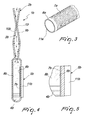
- Figure 6 illustrates a possible different shape of the body of the radiator, which in this constructive variation is designated by the reference numeral 2c.
- the body of the radiator 2c is constituted by a tubular structure, like the tubular radiators that are currently commercially available.
- the receptacle 8a for the liquid introduced in the chamber defined inside the body of the radiator 2c can be formed at the lower end of the body of the radiator 2c and the heating means can be constituted, in a manner similar to what is described with reference to the first embodiment, by a transit duct 11a for a heating fluid which is introduced within the receptacle 8a and is sealed hermetically with the body of the radiator 2c.
- the capillary structure 7a, 7b besides performing the function of conveying the liquid 4a, 4b on the heat exchange surface 6a, 6b between the heating means 5a, 5b and the liquid 4a, 4b, provides a plurality of microcavities on the heat exchange surface 6a, 6b which facilitate, during evaporation, the formation of a large number of microbubbles of vapor with a consequent increase in thermal efficiency.
- the presence of the capillary structure 7a, 7b conveys by capillary action the liquid 4a, 4b onto the heat exchange surface 6a, 6b.
- the heat provided by the heating means 5a, 5b to the liquid 4a, 4b which is on the heat exchange surface 6a, 6b produces the progressive evaporation of the liquid 4a, 4b and the generated steam rises, contacting the inner surface of the body of the radiator 2a, 2b, 2c which is at a lower temperature. This contact causes the cooling of the vapor and therefore its condensation and a heating of the body of the radiator 2a, 2b, 2c which transmits such heat to the surrounding environment and cools.
- the condensate collects inside the receptacle 8a, 8b, where it is again conveyed onto the heat exchange surface 6a, 6b by the capillary structure 7a, 7b, where it undergoes a new heating and evaporates again, rising and contacting again the inner surface of the body of the radiator 2a, 2b, 2c, which by being at a lower temperature again causes the condensation of this vapor, continuing the cycle that has already been described.
- the radiator according to the invention can work with heating temperatures of the liquid 4a, 4b which are even relatively low, for example around 40-50°C, ensuring high thermal efficiency thanks to the heat exchange that occurs with vapor condensation.
- the radiator according to the invention is capable of ensuring very quiet operation.
- the radiator according to the invention fully achieves the intended aim, since due to the arrangement of the heat exchange surface with respect to the free surface of the liquid to be evaporated and due to the presence of the capillary structure it ensures very quiet operation and high heat exchange efficiency, which add to the already high heat exchange efficiency that derives from the utilization of the heat released by the liquid during phase transition.
- the materials used although the use of stainless steel is preferred for the provision of the body of the radiator, as well as the dimensions, may be any according to requirements and to the state of the art.
Landscapes
- Engineering & Computer Science (AREA)
- Physics & Mathematics (AREA)
- Thermal Sciences (AREA)
- Mechanical Engineering (AREA)
- General Engineering & Computer Science (AREA)
- Chemical & Material Sciences (AREA)
- Combustion & Propulsion (AREA)
- Life Sciences & Earth Sciences (AREA)
- Sustainable Development (AREA)
- Central Heating Systems (AREA)
- Resistance Heating (AREA)
Applications Claiming Priority (1)
| Application Number | Priority Date | Filing Date | Title |
|---|---|---|---|
| ITMI20071332 ITMI20071332A1 (it) | 2007-07-04 | 2007-07-04 | Radiatore, particolarmente per impianti di riscaldamento o simili, ad elevate prestazioni termiche e ad elevata silenziosita' di funzionamento. |
Publications (2)
| Publication Number | Publication Date |
|---|---|
| EP2012080A2 true EP2012080A2 (de) | 2009-01-07 |
| EP2012080A3 EP2012080A3 (de) | 2010-04-07 |
Family
ID=39831811
Family Applications (1)
| Application Number | Title | Priority Date | Filing Date |
|---|---|---|---|
| EP08158106A Withdrawn EP2012080A3 (de) | 2007-07-04 | 2008-06-12 | Heizkörper, insbesondere für Heizsysteme u.ä., mit hoher Heizleistung und sehr leisem Betrieb |
Country Status (2)
| Country | Link |
|---|---|
| EP (1) | EP2012080A3 (de) |
| IT (1) | ITMI20071332A1 (de) |
Cited By (5)
| Publication number | Priority date | Publication date | Assignee | Title |
|---|---|---|---|---|
| ITRM20110447A1 (it) * | 2011-08-25 | 2013-02-26 | I R C A S P A Ind Resistenz E Corazzate E | Radiatore a scambio termico bifasico con ottimizzazione del transitorio di ebollizione |
| ITRM20110449A1 (it) * | 2011-08-25 | 2013-02-26 | I R C A S P A Ind Resistenz E Corazzate E | Radiatore idronico-bifasico a inerzia termica ridotta e basso impatto ambientale |
| RU2476802C2 (ru) * | 2011-10-27 | 2013-02-27 | Михаил Владимирович Бородин | Радиатор отопления из тепловой трубы |
| RU2563328C1 (ru) * | 2014-11-06 | 2015-09-20 | Федеральное государственное бюджетное образовательное учреждение высшего профессионального образования "Алтайский государственный аграрный университет" (ФГБОУ ВПО АГАУ) | Радиатор отопления |
| RU2703069C1 (ru) * | 2019-02-25 | 2019-10-16 | Ирина Владимировна Дёмина | Теплообменное устройство |
Citations (1)
| Publication number | Priority date | Publication date | Assignee | Title |
|---|---|---|---|---|
| FR2357850A1 (fr) | 1976-07-06 | 1978-02-03 | Zanussi A Spa Industrie | Radiateur pour installations de chauffage ou l'equivalent |
Family Cites Families (6)
| Publication number | Priority date | Publication date | Assignee | Title |
|---|---|---|---|---|
| US1750907A (en) * | 1929-01-16 | 1930-03-18 | John F Skold | Electrically-heated radiator |
| GB2099980B (en) * | 1981-05-06 | 1985-04-24 | Scurrah Norman Hugh | Heat transfer panels |
| GB2286881B (en) * | 1994-02-22 | 1998-09-16 | British Gas Plc | Thermosyphon radiators |
| DE102005002840A1 (de) * | 2005-01-20 | 2006-08-03 | The Heating Company Bvba | Heizkörper mit einem äußeren elektrischen Heizelement |
| TWI275765B (en) * | 2005-01-28 | 2007-03-11 | Foxconn Tech Co Ltd | Wick structure, method of manufacturing the wick structure, and heat pipe |
| KR200387377Y1 (ko) * | 2005-03-18 | 2005-06-17 | 배민현 | 히트파이프 열교환기의 전열관 구조 |
-
2007
- 2007-07-04 IT ITMI20071332 patent/ITMI20071332A1/it unknown
-
2008
- 2008-06-12 EP EP08158106A patent/EP2012080A3/de not_active Withdrawn
Patent Citations (1)
| Publication number | Priority date | Publication date | Assignee | Title |
|---|---|---|---|---|
| FR2357850A1 (fr) | 1976-07-06 | 1978-02-03 | Zanussi A Spa Industrie | Radiateur pour installations de chauffage ou l'equivalent |
Cited By (9)
| Publication number | Priority date | Publication date | Assignee | Title |
|---|---|---|---|---|
| ITRM20110447A1 (it) * | 2011-08-25 | 2013-02-26 | I R C A S P A Ind Resistenz E Corazzate E | Radiatore a scambio termico bifasico con ottimizzazione del transitorio di ebollizione |
| ITRM20110449A1 (it) * | 2011-08-25 | 2013-02-26 | I R C A S P A Ind Resistenz E Corazzate E | Radiatore idronico-bifasico a inerzia termica ridotta e basso impatto ambientale |
| WO2013027194A1 (en) * | 2011-08-25 | 2013-02-28 | I.R.C.A. S.P.A. Industria Resistenze Corazzate E Affini | Hydronic/biphasic radiator with reduced thermal inertia and low environmental impact |
| WO2013027193A1 (en) * | 2011-08-25 | 2013-02-28 | I.R.C.A. S.P.A. Industria Resistenze Corazzate E Affini | Biphasic heat exchange radiator with optimisation of the boiling transient |
| US9581390B2 (en) | 2011-08-25 | 2017-02-28 | I.R.C.A. S.P.A. Industria Resistenze Corazzate E Affini | Biphasic heat exchange radiator with optimisation of the boiling transient |
| US9829251B2 (en) | 2011-08-25 | 2017-11-28 | I.R.C.A. S.P.A. Industria Resistenze Corazzate E Affini | Hydronic/biphasic radiator with reduced thermal inertia and low environmental impact |
| RU2476802C2 (ru) * | 2011-10-27 | 2013-02-27 | Михаил Владимирович Бородин | Радиатор отопления из тепловой трубы |
| RU2563328C1 (ru) * | 2014-11-06 | 2015-09-20 | Федеральное государственное бюджетное образовательное учреждение высшего профессионального образования "Алтайский государственный аграрный университет" (ФГБОУ ВПО АГАУ) | Радиатор отопления |
| RU2703069C1 (ru) * | 2019-02-25 | 2019-10-16 | Ирина Владимировна Дёмина | Теплообменное устройство |
Also Published As
| Publication number | Publication date |
|---|---|
| EP2012080A3 (de) | 2010-04-07 |
| ITMI20071332A1 (it) | 2009-01-05 |
Similar Documents
| Publication | Publication Date | Title |
|---|---|---|
| CN100572908C (zh) | 发光二极管灯具 | |
| EP2012080A2 (de) | Heizkörper, insbesondere für Heizsysteme u.ä., mit hoher Heizleistung und sehr leisem Betrieb | |
| EP2713132A1 (de) | Vorrichtung zur Wärmeübertragung durch Verdampfung | |
| JP2010249414A (ja) | 熱交換器 | |
| CN106415184B (zh) | 热传递装置 | |
| CN100414243C (zh) | 沸腾冷却装置 | |
| CN105464948B (zh) | 一种强化冰箱压缩机壳体散热性能的装置 | |
| CN205330920U (zh) | 强化冰箱压缩机壳体散热性能的装置 | |
| TWI596313B (zh) | 散熱裝置 | |
| CN105246302B (zh) | 一种热管散热装置 | |
| EP0978250A2 (de) | Vorrichtung zum Geschirrtrocknen am Ende des Waschverfahrens einer Geschirrspülmaschine | |
| KR20180101566A (ko) | 진동 미니-채널 조리도구 | |
| KR200242427Y1 (ko) | 고효율 열매체 방열기를 이용한 3중관 열교환기 및 이를이용한 보일러장치 | |
| EP3063481B1 (de) | Kältevorrichtung mit verbessertem tauwassersammelbehälter | |
| CN215453789U (zh) | 散热器 | |
| KR20190081999A (ko) | 루프형 히트 파이프 | |
| CN105758237A (zh) | 一种具有纵横热管的散热器 | |
| CN110829896B (zh) | 基于机械泵和毛细泵互补作用的碱金属热电转换器 | |
| RU2322643C2 (ru) | Нагревательный прибор систем отопления помещений | |
| CN205105508U (zh) | 一种热管散热装置 | |
| CN117663091A (zh) | 蒸汽发生装置 | |
| RU2563328C1 (ru) | Радиатор отопления | |
| CN220689866U (zh) | 一种热管结构及换热设备 | |
| JP5569328B2 (ja) | 熱機関 | |
| CN204084816U (zh) | 回收水蒸气余热的预热式电热器 |
Legal Events
| Date | Code | Title | Description |
|---|---|---|---|
| PUAI | Public reference made under article 153(3) epc to a published international application that has entered the european phase |
Free format text: ORIGINAL CODE: 0009012 |
|
| AK | Designated contracting states |
Kind code of ref document: A2 Designated state(s): AT BE BG CH CY CZ DE DK EE ES FI FR GB GR HR HU IE IS IT LI LT LU LV MC MT NL NO PL PT RO SE SI SK TR |
|
| AX | Request for extension of the european patent |
Extension state: AL BA MK RS |
|
| PUAL | Search report despatched |
Free format text: ORIGINAL CODE: 0009013 |
|
| AK | Designated contracting states |
Kind code of ref document: A3 Designated state(s): AT BE BG CH CY CZ DE DK EE ES FI FR GB GR HR HU IE IS IT LI LT LU LV MC MT NL NO PL PT RO SE SI SK TR |
|
| AX | Request for extension of the european patent |
Extension state: AL BA MK RS |
|
| AKY | No designation fees paid | ||
| REG | Reference to a national code |
Ref country code: DE Ref legal event code: 8566 |
|
| STAA | Information on the status of an ep patent application or granted ep patent |
Free format text: STATUS: THE APPLICATION IS DEEMED TO BE WITHDRAWN |
|
| 18D | Application deemed to be withdrawn |
Effective date: 20101008 |