EP2012098A1 - Capteur fonctionnant selon le principe TDR doté d'une sonde coaxiale et procédé de fabrication correspondant - Google Patents
Capteur fonctionnant selon le principe TDR doté d'une sonde coaxiale et procédé de fabrication correspondant Download PDFInfo
- Publication number
- EP2012098A1 EP2012098A1 EP08104109A EP08104109A EP2012098A1 EP 2012098 A1 EP2012098 A1 EP 2012098A1 EP 08104109 A EP08104109 A EP 08104109A EP 08104109 A EP08104109 A EP 08104109A EP 2012098 A1 EP2012098 A1 EP 2012098A1
- Authority
- EP
- European Patent Office
- Prior art keywords
- probe
- sensor
- outer conductor
- conductor
- inner conductor
- Prior art date
- Legal status (The legal status is an assumption and is not a legal conclusion. Google has not performed a legal analysis and makes no representation as to the accuracy of the status listed.)
- Withdrawn
Links
Images


Classifications
-
- G—PHYSICS
- G01—MEASURING; TESTING
- G01F—MEASURING VOLUME, VOLUME FLOW, MASS FLOW OR LIQUID LEVEL; METERING BY VOLUME
- G01F23/00—Indicating or measuring liquid level or level of fluent solid material, e.g. indicating in terms of volume or indicating by means of an alarm
- G01F23/22—Indicating or measuring liquid level or level of fluent solid material, e.g. indicating in terms of volume or indicating by means of an alarm by measuring physical variables, other than linear dimensions, pressure or weight, dependent on the level to be measured, e.g. by difference of heat transfer of steam or water
- G01F23/28—Indicating or measuring liquid level or level of fluent solid material, e.g. indicating in terms of volume or indicating by means of an alarm by measuring physical variables, other than linear dimensions, pressure or weight, dependent on the level to be measured, e.g. by difference of heat transfer of steam or water by measuring the variations of parameters of electromagnetic or acoustic waves applied directly to the liquid or fluent solid material
- G01F23/284—Electromagnetic waves
Definitions
- the invention relates to a sensor according to the TDR principle with a coaxial probe according to the preamble of claim 1, the use of the sensor as a level sensor and a manufacturing method for the sensor.
- the TDR measurement principle (time domain reflectometry) is based on the determination of propagation times of an electromagnetic pulse, for determining the distance of a discontinuity of the line resistance, such as a cable break or a product interface. It is therefore similar to radar, the difference being that the electromagnetic waves are not emitted to the outside, but are guided along a conductor.
- One of the oldest applications of the TDR principle is the localization of breaks in overseas pipelines.
- a common field of application for sensors based on the TDR principle is the determination of levels.
- an electromagnetic pulse is emitted along a conductor, wherein the pulse is partially reflected by the change in the dielectric constant between different media in a container and it is thereby possible to determine the distance between interface and sensor over a transit time measurement and thus to the level to calculate.
- level sensors In such level sensors is still distinguished between open probes and closed probes.
- the former consist of a simple conductor and use the environment as the opposite pole of the probe coupling.
- the field of application of such sensors is therefore limited to containers of conductive material. Especially in the upper region of the container, the wave propagation depends to a considerable extent on the geometry of the container and thus impairs the measurement accuracy of the sensor.
- Closed probes consist of a coaxial conductor, which itself brings along its inner conductor and outer conductor.
- the microwave is guided by the coaxial conductor, whereby the sensor becomes independent of the container in which it is inserted.
- the prerequisite here is that the liquids to be measured within the coaxial conductor have the same level as in the container.
- the known solutions for liquid exchange between the interior of the coaxial conductor and the container are unsatisfactory.
- holes are introduced (punched, drilled, etc.) into the tube-shaped outer conductor, which then change the openings due to the whereabouts of processing residues and thus disturb the characteristic impedance of the probe and thus the measurement itself.
- the corresponding processing of the outer conductor is associated with great effort.
- a strong interference signal is superimposed on the measuring signal in the case of TDR sensors due to the strong characteristic impedance change of the probe end.
- a measurement signal near the end of the probe is thus partially or completely lost, so that there is a dead zone.
- Low levels in a container can therefore not be measured, which becomes more troublesome the smaller the container is.
- a theoretical way to reduce the deadband is to attach a resistor to the end of the coaxial probe. The possibility of wave adaptation suppresses the interference pulse of the probe end and thus reduces the artifact.
- the resistor and its connections to the probe must be able to withstand the stresses caused by a circulating liquid. Above all, however, the resistor must have very good high-frequency behavior so that the adaptation actually takes place. The requirements of the adaptation become increasingly more difficult with increasing bandwidth (working frequency). Since another way to reduce the dead zone is to increase just this working frequency in order to obtain steeper pulses that can be differentiated better, such a solution with one or more parallel resistors is only theoretically feasible.
- an object of the invention is to provide a sensor according to the TDR principle, which reliably delivers accurate measurement results, regardless of the geometry of the environment and in particular of a container geometry.
- a sensor with a coaxial probe is associated with a terminating element which electrically connects the inner conductor and the outer conductor via an inductive element.
- the effect of this inductive element is that the artifact pulse at the probe end is delayed by the inductive resistor.
- a measuring pulse in the vicinity of the probe end does not reach the inductive element and is therefore not delayed by this. This results in a temporal decoupling, which makes it possible to reduce the dead zone quite considerably.
- the probe is thus virtually extended from the viewpoint of the electromagnetic signals, so that the actual length of the probe can be fully or almost completely utilized as a measuring range.
- the advantage of the probe according to the invention is thus in the extended use of any external geometries and in more accurate measurement results.
- At least one spacer is provided, in particular made of PTFE or PBT, which keeps the inner conductor spaced from the outer conductor over the entire course of the probe.
- PTFE or PBT PTFE
- the specified materials are suitable both for their electromagnetic properties and their mechanical resistance to contamination by the liquids from which they are washed.
- the spacer element comprises a small angle segment, in particular less than 45 °, of the circumference of the probe and has one or more projections, which surround the outer conductor and / or the inner conductor in a larger angular segment and / or the spacer element in an angle with reduced Field strength is located.
- the area is kept small, in which the spacer influences the propagation of the electromagnetic waves.
- the spacer is located in an angular segment of the probe, in which the field strength of the measuring pulse is small.
- the projections or hooks of the spacers in spite of the small geometry of the spacer elements in themselves provide a stable mechanical support. The spacer only slightly affects the field when it is in a contra-angle with reduced field strength, and thus ensures the smallest possible change in the measured values.
- the inductive element comprises a coil or a spiral spring. Both can be easily integrated into the terminating element and produced with the desired inductance.
- the terminating element preferably has a capacitive element, in particular a shaft securing disk, which is connected to the probe or snapped onto the inner conductor.
- a shaft retainer or washer is easily integrated into the mechanical design of the probe, and the additional capacitance provides further signal optimization which levels the signal from the artifact of the probe end, further simplifying the distinction between the artifact and the measuring pulse.
- the terminating element is at the same time designed as a spacer element, in particular as a spiral spring, which generates both the mechanical and the inductive properties of the terminating element.
- the end element thus receives a dual function, supports the mechanical stability of the probe and makes even with short probes additional spacers even superfluous.
- the outer conductor openings in particular elongated slots to allow a fluid exchange
- the surfaces of the outer conductor are smooth even in the region of the openings. This ensures that the measured level within the probe corresponds to the outer level to be determined, even with several liquid phases, such. For example, oil on water.
- a smooth surface without burrs or machining residues facilitates this fluid exchange and reduces electromagnetic interference through the slots.
- the outer conductor particularly preferably has a polygonal cross section and a connecting line, in particular a weld, over the length of the probe.
- a connecting line in particular a weld
- the spacer elements are arranged in openings of the outer conductor, in particular in pairs from opposite sides in the circumferential direction of the probe.
- the inner conductor is held in position, although the spacer elements do not completely surround the inner conductor, but a large part of the inner conductor is free and can make direct contact with the measuring medium. Signal technically so the spacers are invisible and thus allow a more accurate and reliable measurement.
- the probe is directly connected to a board of the controller.
- This direct connection eliminates the need for a sophisticated high-frequency Tank pressat tion and their connection, thus ensuring a more compact, less susceptible and less expensive construction.
- connection between the probe and the circuit board preferably has soft pads, which are arranged in particular in a circular manner corresponding to the circumference of the probe on the circuit board.
- the connection can thus be prepared already during the assembly of the board. The attachment of the probe requires only a simple manufacturing step and thus reduces the effort.
- a particularly important application of the sensor according to the invention is that as a level sensor according to claim 12. Due to the reduced dead zone, it is possible to use the probe in small containers and to measure low water levels. Since the probe is coaxial, the measurement results are independent of the vessel geometry.
- the manufacturing method according to the invention according to claim 13 enables a particularly cost-effective production and avoids the disturbing effects of punching burrs. For a particularly good fluid exchange between the interior of the probe and container is guaranteed.
- the probe produced in this way furthermore has the reduced deadband already described in connection with claim 1.
- the manufacturing method can be configured in a similar manner by further features, such as the probe according to the invention, and shows similar advantages.
- Such further features are exemplary, but not exhaustive, in which subclaims following the independent claims are described.
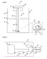
- FIG. 1 schematically shows an embodiment of the sensor 10 according to the invention, which is mounted as a level sensor in a container 12 with a liquid 14.
- the liquid 14 forms an interface 18 with respect to the air 16.
- the sensor 10 is designed to determine the distance of the interface 18 and to deduce the level of the liquid 14 from its known mounting position and the geometry of the container 12.
- the formation of the sensor 10 as a level sensor is a very important field of use, the sensor 10 can in principle also be used in other areas in which an interface is to be located. In particular, other interfaces 18 are to be considered, for example between different liquids or granules.
- the sensor 10 has a sensor head 20 with a controller 22, which is preferably accommodated on a common board.
- a coaxial probe 24 is directly attached, which has an outer conductor 26 and an inner conductor 28.
- the connection of the two conductors 26, 28 of the coaxial probe 24 with the board of the controller 22 is carried out directly by a soldered to the board pin and a matching socket which is brought into interference fit with a blind hole of the inner conductor 26, as well as circularly arranged so-called soft Pads (GORE components), which connects the board with the outer conductor 26 low impedance. Due to the circular arrangement and the direct coupling of the outer conductor with the printed circuit board or board a reflection-poor connection between outer conductor 26 and board 22 of the control is provided.
- the soft pads can absorb at least a certain mechanical tolerance.
- a closing element 30 is provided, which is enlarged again for clarity in a cutout 32 and shown in plan view.
- the terminating element 30 electrically connects the inner conductor 28 to the outer conductor 26 via a helical spring 34. As a result, this electrical connection has an inductance.
- the spiral spring 34 not only provides an electrical connection, but also ensures, by mechanical strength, that the inner conductor 28 is centrally spaced from the outer conductor 26.
- an element with capacitive behavior can also be provided in the terminating element 30. Such an element can be realized, for example, by a spring washer applied to the inner conductor.
- An example of a terminator is in the FIGS. 9a and 9b shown.
- the provided in the sensor head 20 controller 22 and its board is in FIG. 2 shown in a block diagram.
- the actual control is a microprocessor 36, which may also be an FPGA, ASIC or the like, and a time base circuit for driving a microwave transmitter 38 and a microwave receiver 40.
- the control of the transmitting and receiving unit leaves the reflected and received at the inner conductor measuring signal time-stretched at the output of the microwave receiver appear.
- the time-expanded measuring signal is passed to the microprocessor 36 for measuring signal evaluation.
- the amplifier 42 is able to adjust to the signal level and thus to be able to evaluate small measurement signals by utilizing the resolution of the analog-to-digital converter.
- FIG. 3 shows a typical waveform of a TDR sensor signal.
- This signal represents the change in the characteristic impedance along the probe 24.
- the signal is supplied from the amplifier 42 to the microprocessor 36 and digitized.
- a pulse is emitted by the microwave transmitter 38 at a time t1 and coupled to the inner conductor 28 of the probe.
- the optimized but not perfect transition between the inner conductor 28 and printed circuit board 22 causes an interference signal immediately after t1, which, however, is temporally still "above" the actual measuring probe and thus does not represent a real disturbance for the signal evaluation.
- the microwave receiver 40 reaches a reflection pulse resulting from the jump in the dielectric constant of air 16 to liquid 14 at the interface 18.
- the controller 22 must solve the task of determining the times t1 and t2 based on the extrema.
- the waveform can be significantly different from the one in FIG. 3 deviate from the typical signal curve shown, so that the determination of the extrema in the known conversions initially requires a determination of a fundamental signal level 44.
- the minimum at t1 and the maximum at t2 is then determined.
- the terminating element 30 is provided according to the invention in order to reduce or avoid the formation of a dead zone at the lower end of the probe 24. This is hereafter based on various in FIG. 4 illustrated signal waveforms explained. Show FIGS. 4a and 4b conventional waveforms while the Figures 4c and 4d Illustrate waveforms with a termination element 30 and an intermediate inductance.
- the invention does not attempt to avoid the artifact of a pulse at the end of the probe 24, but shifts this artifact backward in time, so that it is not or at least less superimposed with the actual measuring pulse from the interface 18.
- the extent of the time shift depends on the inductance and can be influenced approximately by the length of the coil spring 34. In this way, the probe 24 is virtually extended, so that the entire real length is available for measurements.
- FIG. 4a shows for comparison the waveform of a received pulse at an open probe 24, that is, if no terminating element 30 is provided.
- This received pulse is referred to below as an artifact.
- the minimum of the artifact is the reference time t0, which corresponds to the end of the probe 24.
- t0 The minimum of the artifact.
- a positive measuring pulse which belongs to a reflection of an interface 18 with a low characteristic impedance jump, superimposes the left flank of the artifact. The controller 22 would not be able to distinguish this measurement pulse from noise and therefore could not measure the low level.
- Figure 4c is the counterpart to FIG. 4a , wherein the end of the probe 24 is closed with the end element 30, so that therefore an inductance between outer conductor 26 and inner conductor 28 is connected.
- the reflection on the terminating element 30, in contrast to the open probe 24, is the FIGS. 4a and 4b delayed and gives a pronounced peak with opposite sign. On the left there is a small remnant of the artifact.
- FIG. 4d the counterpart to FIG. 4b
- the measurement pulse is still superimposed with the delayed artifact, it itself forms a distinct peak which the controller 22 can recognize.
- a low level can thus be measured.
- the dead zone can therefore be reduced or even avoided by selecting the inductance.
- a mechanical element such as a shaft lock washer, is provided around the inner conductor 28 in the terminating element 30, this acts as a capacitance and further optimizes the signal shape.
- another capacitive element may be provided. The capacity causes the waveform to level out before the delayed artifact. In other words, the residual left negative pulse disappears in Figure 4c so that the signal quality is further improved and the distinctness between measurement signal and artifact is facilitated.
- spacers 46 themselves also change the waveguiding properties of the probe 24. Therefore, as the material of the spacers 46, one with the lowest possible dielectric constant is used, for example polytetrafluoroethylene (PTFE, Teflon) or polybutylene terephthalate (PBT).
- PTFE polytetrafluoroethylene
- Teflon Teflon
- PBT polybutylene terephthalate
- the error introduced by the changed waveguide properties is reduced or prevented by using a plurality or a continuous spacer element.
- the material of the spacer elements and the error introduced thereby is distributed, in the case of a continuous spacer it disappears completely.
- the outer conductor 26 has elongated slots or openings 48, which allows a fluid exchange between the interior of the probe 24 and the container 12. This is related to the FIGS. 7 and 8 explained later in more detail.
- the spacer 46 (solid line) is inserted through this opening 48 in the outer conductor 26 (dashed line) and thus centered the inner conductor 28th
- the radial field lines 50 sketch the resulting electromagnetic field. Since the spacer 46 fills only a small portion of the entire interior of the outer- zincleiters 26, so only a small angle segment, in particular less than 45 °, the disturbance of the field remains very low. In addition, the spacer is located in an angular segment of the probe, in which the electromagnetic field is reduced and thus causes only a very small amount of noise. The field is therefore particularly weak in this angle section, because here the field lines coming from the inner conductor are led away laterally to the edges of the outer conductor. In order to increase the stability on the inner conductor 28, a narrow hook-like projection or hook 52 surrounds the inner conductor 28 in a larger angular range. Since the hook 52 of the spacer element 46 consists of only a very small amount of material, the measuring error introduced as a result is negligible. Corresponding hooks 52 also stabilize the spacer 46 on the outer conductor 26.
- spacer elements 46 are each offset in the circumferential direction, they not only ensure mechanical stability in all radial directions.
- a simple such configuration is in FIG. 6 shown, in which two opposite spacers 46 center the inner conductor 28. According to the invention, it is therefore possible to ensure the mechanical stability of the probe 24 without introducing a significant measuring error.
- FIG. 7 a difficulty of measuring the object of liquids is illustrated.
- the prerequisite for an accurate measurement is that within the probe 24, the level corresponds to that within the container 12.
- two liquids, namely water 15a and oil 15b are stacked in the container 12. This results in an interface 18a between the water 15a and the oil 15b and another interface 18b between the oil 15b and the air 16.
- the inner water level of the water 19a and the inner water level 19b of the oil differ from that in the container 12.
- the outer conductor 26 has a number of elongated slots or openings. In a finished tubular outer conductor 26, such slots 48 can not be readily attached. In addition, when punching an inner punching burr would remain, which impedes fluid exchange as wave propagation.
- the outer conductor 26 is made of a flat starting material, such as a metal sheet, as shown in FIG. 8a is shown.
- a flat starting material such as a metal sheet
- openings 48 are attached, for example by punching or laser cutting. Since both surfaces are still flat, no burrs occur, or they can at least be leveled, which would not be possible on the inside of a tubular outer conductor.
- the openings 48 may be applied in a regular or irregular pattern. In terms of number and size, consideration should be given to mechanical stability, fluid exchange and disturbance of wave propagation. The illustrated regular arrangement is therefore to be understood as an example only.
- the sheet-like starting material is folded or rolled like a tube as indicated by arrows 54a and 54b.
- the simpler processing compared to a regular rolling is a multiple folding.
- a regular polygon for example, with ten corners, to choose to approximate a circle.
- the resulting tube is longitudinally connected to the contacting outer boundaries 56, for example by welding.
- the spacer element 30 can be placed so that the inner conductor 28 and outer conductor 26 are connected via the inductive element 34.
- the probe 24 is inserted into the sensor head 20 and contacts the soft pads of the board of the controller 22, and the inner conductor 28 contacts the intended socket of this board. This direct contact saves high-frequency lines between the probe 24 and the board.
Landscapes
- Physics & Mathematics (AREA)
- Electromagnetism (AREA)
- Thermal Sciences (AREA)
- Fluid Mechanics (AREA)
- General Physics & Mathematics (AREA)
- Measurement Of Levels Of Liquids Or Fluent Solid Materials (AREA)
Applications Claiming Priority (1)
| Application Number | Priority Date | Filing Date | Title |
|---|---|---|---|
| DE200710030847 DE102007030847A1 (de) | 2007-07-03 | 2007-07-03 | Sensor nach dem TDR-Prinzip mit einer koaxialen Sonde und Herstellungsverfahren dafür |
Publications (1)
| Publication Number | Publication Date |
|---|---|
| EP2012098A1 true EP2012098A1 (fr) | 2009-01-07 |
Family
ID=39684086
Family Applications (1)
| Application Number | Title | Priority Date | Filing Date |
|---|---|---|---|
| EP08104109A Withdrawn EP2012098A1 (fr) | 2007-07-03 | 2008-05-27 | Capteur fonctionnant selon le principe TDR doté d'une sonde coaxiale et procédé de fabrication correspondant |
Country Status (2)
| Country | Link |
|---|---|
| EP (1) | EP2012098A1 (fr) |
| DE (2) | DE102007030847A1 (fr) |
Cited By (15)
| Publication number | Priority date | Publication date | Assignee | Title |
|---|---|---|---|---|
| DE202009008744U1 (de) | 2009-06-25 | 2010-11-11 | Sick Ag | Füllstandssensor |
| GB2466162B (en) * | 2007-10-01 | 2012-12-05 | Vibro Meter Inc | System and method for accurately measuring fluid level in a vessel |
| US8549909B2 (en) | 2007-10-01 | 2013-10-08 | Meggitt (Orange County), Inc. | Vessel probe connector with solid dielectric therein |
| DE102012218574A1 (de) | 2012-10-11 | 2014-04-17 | Frima - T Sas | Sensor |
| DE202013100830U1 (de) | 2013-02-26 | 2014-06-04 | Sick Ag | Optoelektronischer Füllstandssensor |
| DE202013100833U1 (de) | 2013-02-26 | 2014-06-04 | Sick Ag | Optoelektronischer Sensor zur Bestimmung eines Füllstands eines Mediums in einem Behälter |
| US8794063B2 (en) | 2007-01-08 | 2014-08-05 | Meggitt (Orange County), Inc. | System and method for optimizing sweep delay and aliasing for time domain reflectometric measurement of liquid height within a tank |
| EP2770308A1 (fr) | 2013-02-26 | 2014-08-27 | Sick Ag | Capteur de niveau de remplissage optoélectronique |
| EP2770307A1 (fr) | 2013-02-26 | 2014-08-27 | Sick Ag | Capteur optoélectronique et procédé de détermination d'un niveau de remplissage d'un fluide dans un récipient |
| WO2015078618A1 (fr) * | 2013-11-27 | 2015-06-04 | Vega Grieshaber Kg | Sonde coaxiale à conducteur intérieur serré |
| WO2015124339A1 (fr) * | 2014-02-18 | 2015-08-27 | Vega Grieshaber Kg | Capteur de niveau de remplissage à système de contrôle d'électrode |
| EP3035041A1 (fr) * | 2014-12-18 | 2016-06-22 | Airbus Defence and Space GmbH | Procédé de détection de paramètre de matériels et dispositif de détermination de paramètre de matériels |
| EP3035043A1 (fr) * | 2014-12-18 | 2016-06-22 | Airbus Defence and Space GmbH | Dispositif de capteur et son procédé de production et dispositif de mesure |
| EP3660494A1 (fr) * | 2018-11-29 | 2020-06-03 | Danfoss A/S | Détection d'une qualité de vapeur |
| CN114593789A (zh) * | 2020-12-03 | 2022-06-07 | 罗斯蒙特储罐雷达股份公司 | 用于减小的下死区的雷达物位计系统和方法 |
Families Citing this family (7)
| Publication number | Priority date | Publication date | Assignee | Title |
|---|---|---|---|---|
| DE102014107393B4 (de) * | 2014-05-26 | 2020-04-23 | Krohne S. A. S. | Abschlusselement für Füllstandmessgerät und Füllstandmessgerät |
| DE202019100659U1 (de) | 2019-02-05 | 2020-05-07 | Sick Ag | Sensor zum Bestimmen einer Prozessgröße |
| DE102019102812A1 (de) * | 2019-02-05 | 2020-08-06 | Sick Ag | Sensor zum Bestimmen einer Prozessgröße |
| DE102019122624B3 (de) | 2019-08-22 | 2020-09-17 | Sick Ag | Prozessanschluss mit einer ringförmigen Formdichtung |
| DE102021111990B3 (de) | 2021-05-07 | 2022-03-17 | Sick Ag | Sensor mit einem in einem Prozessanschluss drehbaren Gehäuse und Verfahren zum Verbinden des Gehäuses mit dem Prozessanschluss |
| DE202021102491U1 (de) | 2021-05-07 | 2022-08-11 | Sick Ag | Sensor zum Bestimmen einer Prozessgröße |
| DE202023104673U1 (de) | 2023-08-17 | 2024-11-22 | Sick Ag | Sensor zum Bestimmen einer Prozessgröße |
Citations (6)
| Publication number | Priority date | Publication date | Assignee | Title |
|---|---|---|---|---|
| US3874237A (en) * | 1973-02-15 | 1975-04-01 | Canadian Patents Dev | Liquid level height measuring apparatus |
| EP0042186A1 (fr) * | 1980-06-13 | 1981-12-23 | Shell Internationale Researchmaatschappij B.V. | Méthode et appareil pour mesurer la position d'une interface entre des matériaux différents par réflectométrie reliée à la fréquence |
| WO2001063219A2 (fr) | 2000-02-23 | 2001-08-30 | Cambridge Consultants Limited | Reflectometrie temporelle |
| DE10043838A1 (de) * | 2000-09-06 | 2002-04-04 | Grieshaber Vega Kg | Füllstandsmeßvorrichtung |
| US20040027137A1 (en) * | 2002-04-29 | 2004-02-12 | Siemens Milltronics Process Instruments Inc. | Time domain reflectometry probe for level sensing |
| DE102004032965A1 (de) * | 2004-07-07 | 2006-02-02 | Endress + Hauser Gmbh + Co. Kg | Vorrichtung zum Ausrichten und Zentrieren eines stab- oder seilförmigen Oberflächenwellenleiters eines Feldgerätes |
Family Cites Families (2)
| Publication number | Priority date | Publication date | Assignee | Title |
|---|---|---|---|---|
| US6293142B1 (en) * | 1998-08-14 | 2001-09-25 | Mts Systems Corporation | Electromagnetic method of liquid level monitoring |
| DE202005020158U1 (de) * | 2005-12-22 | 2007-02-15 | Sailer, Josef | Messsystem zur Messung des Abstands bis zu einem Messmedium |
-
2007
- 2007-07-03 DE DE200710030847 patent/DE102007030847A1/de not_active Withdrawn
-
2008
- 2008-05-27 DE DE200820018156 patent/DE202008018156U1/de not_active Expired - Lifetime
- 2008-05-27 EP EP08104109A patent/EP2012098A1/fr not_active Withdrawn
Patent Citations (6)
| Publication number | Priority date | Publication date | Assignee | Title |
|---|---|---|---|---|
| US3874237A (en) * | 1973-02-15 | 1975-04-01 | Canadian Patents Dev | Liquid level height measuring apparatus |
| EP0042186A1 (fr) * | 1980-06-13 | 1981-12-23 | Shell Internationale Researchmaatschappij B.V. | Méthode et appareil pour mesurer la position d'une interface entre des matériaux différents par réflectométrie reliée à la fréquence |
| WO2001063219A2 (fr) | 2000-02-23 | 2001-08-30 | Cambridge Consultants Limited | Reflectometrie temporelle |
| DE10043838A1 (de) * | 2000-09-06 | 2002-04-04 | Grieshaber Vega Kg | Füllstandsmeßvorrichtung |
| US20040027137A1 (en) * | 2002-04-29 | 2004-02-12 | Siemens Milltronics Process Instruments Inc. | Time domain reflectometry probe for level sensing |
| DE102004032965A1 (de) * | 2004-07-07 | 2006-02-02 | Endress + Hauser Gmbh + Co. Kg | Vorrichtung zum Ausrichten und Zentrieren eines stab- oder seilförmigen Oberflächenwellenleiters eines Feldgerätes |
Cited By (27)
| Publication number | Priority date | Publication date | Assignee | Title |
|---|---|---|---|---|
| US8794063B2 (en) | 2007-01-08 | 2014-08-05 | Meggitt (Orange County), Inc. | System and method for optimizing sweep delay and aliasing for time domain reflectometric measurement of liquid height within a tank |
| US9453755B2 (en) | 2007-10-01 | 2016-09-27 | Meggitt (Orange County), Inc. | TDR fluid level sensor |
| GB2466162B (en) * | 2007-10-01 | 2012-12-05 | Vibro Meter Inc | System and method for accurately measuring fluid level in a vessel |
| US8393208B2 (en) | 2007-10-01 | 2013-03-12 | Meggitt (New Hampshire), Inc. | Measuring of fluid in a vessel with two coaxial cable sections and a coupling therebetween using time domain reflectometry |
| US8549909B2 (en) | 2007-10-01 | 2013-10-08 | Meggitt (Orange County), Inc. | Vessel probe connector with solid dielectric therein |
| DE202009008744U1 (de) | 2009-06-25 | 2010-11-11 | Sick Ag | Füllstandssensor |
| DE102012218574A1 (de) | 2012-10-11 | 2014-04-17 | Frima - T Sas | Sensor |
| DE102012218574B4 (de) | 2012-10-11 | 2019-10-24 | Rational Wittenheim Sas | Sensor |
| DE202013100833U1 (de) | 2013-02-26 | 2014-06-04 | Sick Ag | Optoelektronischer Sensor zur Bestimmung eines Füllstands eines Mediums in einem Behälter |
| EP2770308A1 (fr) | 2013-02-26 | 2014-08-27 | Sick Ag | Capteur de niveau de remplissage optoélectronique |
| DE102013101889A1 (de) | 2013-02-26 | 2014-08-28 | Sick Ag | Optoelektronischer Füllstandssensor |
| DE102013101890A1 (de) | 2013-02-26 | 2014-08-28 | Sick Ag | Optoelektronischer Sensor und Verfahren zur Bestimmung eines Füllstands eines Mediums in einem Behälter |
| EP2770307A1 (fr) | 2013-02-26 | 2014-08-27 | Sick Ag | Capteur optoélectronique et procédé de détermination d'un niveau de remplissage d'un fluide dans un récipient |
| DE102013101890B4 (de) * | 2013-02-26 | 2016-06-02 | Sick Ag | Optoelektronischer Sensor und Verfahren zur Bestimmung eines Füllstands eines Mediums in einem Behälter |
| DE202013100830U1 (de) | 2013-02-26 | 2014-06-04 | Sick Ag | Optoelektronischer Füllstandssensor |
| WO2015078618A1 (fr) * | 2013-11-27 | 2015-06-04 | Vega Grieshaber Kg | Sonde coaxiale à conducteur intérieur serré |
| US10222250B2 (en) | 2013-11-27 | 2019-03-05 | Vega Grieshaber Kg | Coaxial probe having a tensioned internal conductor |
| KR20160090822A (ko) * | 2013-11-27 | 2016-08-01 | 베가 그리이샤버 카게 | 긴장된 내측 도전체를 구비한 동축 프로브 |
| WO2015124339A1 (fr) * | 2014-02-18 | 2015-08-27 | Vega Grieshaber Kg | Capteur de niveau de remplissage à système de contrôle d'électrode |
| EP3035043A1 (fr) * | 2014-12-18 | 2016-06-22 | Airbus Defence and Space GmbH | Dispositif de capteur et son procédé de production et dispositif de mesure |
| EP3035041A1 (fr) * | 2014-12-18 | 2016-06-22 | Airbus Defence and Space GmbH | Procédé de détection de paramètre de matériels et dispositif de détermination de paramètre de matériels |
| EP3660494A1 (fr) * | 2018-11-29 | 2020-06-03 | Danfoss A/S | Détection d'une qualité de vapeur |
| WO2020109212A1 (fr) * | 2018-11-29 | 2020-06-04 | Danfoss A/S | Détection d'une qualité de vapeur |
| CN114593789A (zh) * | 2020-12-03 | 2022-06-07 | 罗斯蒙特储罐雷达股份公司 | 用于减小的下死区的雷达物位计系统和方法 |
| EP4009011A1 (fr) | 2020-12-03 | 2022-06-08 | Rosemount Tank Radar AB | Système et procédé de jauge de niveau radar pour une zone morte inférieure réduite |
| US20220178730A1 (en) * | 2020-12-03 | 2022-06-09 | Rosemount Tank Radar Ab | Radar level gauge system and method for reduced lower dead zone |
| US11933655B2 (en) * | 2020-12-03 | 2024-03-19 | Rosemount Tank Radar Ab | Radar level gauge system and method for reduced lower dead zone |
Also Published As
| Publication number | Publication date |
|---|---|
| DE202008018156U1 (de) | 2011-12-22 |
| DE102007030847A1 (de) | 2009-01-15 |
Similar Documents
| Publication | Publication Date | Title |
|---|---|---|
| EP2012098A1 (fr) | Capteur fonctionnant selon le principe TDR doté d'une sonde coaxiale et procédé de fabrication correspondant | |
| EP2154495B1 (fr) | Capteur TDR et procédé de mesure | |
| EP2010871B1 (fr) | Procédé pour déterminer et surveiller le niveau de remplissage d'un fluide dans un récipient | |
| DE102007042042B4 (de) | Verfahren zur Ermittlung und Überwachung des Füllstands eines Mediums in einem Behälter nach einem Laufzeitmessverfahren | |
| EP3418700B1 (fr) | Appareil de radiodétection de niveau de remplissage à adaptation automatique de la fréquence | |
| DE102007060579B4 (de) | Verfahren zur Ermittlung und/oder zur Beurteilung des Befüllzustands eines mit zumindest einem Medium gefüllten Behälters | |
| EP2104839A1 (fr) | Procédé pour déterminer et surveiller le niveau d'un fluide dans un récipient selon un procédé de mesure du temps de propagation | |
| EP0821431B1 (fr) | Dispositif de production et d'émission de micro-ondes, notamment pour un appareil pour la mesure de niveau | |
| EP1972905B1 (fr) | Dispositif de mesure du niveau de remplissage | |
| WO2009077435A2 (fr) | Dispositif de détermination et/ou de surveillance d'au moins un niveau d'au moins un milieu dans un contenant, par un procédé de mesure du temps de transit et/ou un procédé de mesure capacitif | |
| EP1412710A1 (fr) | Procede pour evaluer les signaux de mesure d'un appareil de mesure fonctionnant selon le principe du temps de propagation | |
| DE102009001010A1 (de) | Verfahren zur Ermittlung und Überwachung des Füllstands eines Mediums in einem Behälter nach einem Laufzeitmessverfahren | |
| EP3025128B1 (fr) | Procédé pour déterminer et surveiller le niveau d'un fluide dans un récipient selon un procédé de mesure du temps de propagation | |
| EP3575755B1 (fr) | Appareil de mesure de niveau de remplissage à commande d'antenne optimisée et méthode de mesure de niveau | |
| WO2019141648A1 (fr) | Procédé et dispositif pour faire fonctionner un capteur acoustique | |
| WO2015161849A1 (fr) | Système radar servant à détecter l'environnement d'un véhicule et carte imprimée destinée à un tel système radar | |
| DE102016214571A1 (de) | Verfahren zum Betrieb einer Ultraschall-Messeinrichtung | |
| WO2002027349A2 (fr) | Procede de detection de l'etat limite d'une matiere et dispositif associe | |
| EP4260021B1 (fr) | Jauge de niveau et procedure d'etalonnage et/ou de verification en ligne d'une jauge de niveau | |
| WO2019072473A1 (fr) | Procédé de détermination du niveau de remplissage d'un produit de remplissage se trouvant dans un récipient | |
| EP1980870B1 (fr) | Capteur optoélectronique et procédé de transmission blindée de signal | |
| EP1186869A2 (fr) | Dispositif de mesure du niveau d' un fluide | |
| DE202008007989U1 (de) | Abstandshalteelement zur Zentrierung eines inneren Leiters | |
| WO2016202533A1 (fr) | Procédé et dispositif de détermination du niveau de remplissage d'un produit de remplissage dans un récipient | |
| DE20016962U1 (de) | Zeitbereichsreflektometer für den Einsatz als Grenzwertschalter zur Erfassung des Grenzstandes eines Gutes |
Legal Events
| Date | Code | Title | Description |
|---|---|---|---|
| PUAI | Public reference made under article 153(3) epc to a published international application that has entered the european phase |
Free format text: ORIGINAL CODE: 0009012 |
|
| 17P | Request for examination filed |
Effective date: 20081015 |
|
| AK | Designated contracting states |
Kind code of ref document: A1 Designated state(s): AT BE BG CH CY CZ DE DK EE ES FI FR GB GR HR HU IE IS IT LI LT LU LV MC MT NL NO PL PT RO SE SI SK TR |
|
| AX | Request for extension of the european patent |
Extension state: AL BA MK RS |
|
| AKX | Designation fees paid |
Designated state(s): AT BE BG CH CY CZ DE DK EE ES FI FR GB GR HR HU IE IS IT LI LT LU LV MC MT NL NO PL PT RO SE SI SK TR |
|
| 17Q | First examination report despatched |
Effective date: 20100305 |
|
| STAA | Information on the status of an ep patent application or granted ep patent |
Free format text: STATUS: THE APPLICATION IS DEEMED TO BE WITHDRAWN |
|
| 18D | Application deemed to be withdrawn |
Effective date: 20111223 |