EP2012119B1 - Appareil et procédé d'analyse de gaz - Google Patents
Appareil et procédé d'analyse de gaz Download PDFInfo
- Publication number
- EP2012119B1 EP2012119B1 EP08252025A EP08252025A EP2012119B1 EP 2012119 B1 EP2012119 B1 EP 2012119B1 EP 08252025 A EP08252025 A EP 08252025A EP 08252025 A EP08252025 A EP 08252025A EP 2012119 B1 EP2012119 B1 EP 2012119B1
- Authority
- EP
- European Patent Office
- Prior art keywords
- reagent
- platform
- droplet
- gas analyzer
- gas
- Prior art date
- Legal status (The legal status is an assumption and is not a legal conclusion. Google has not performed a legal analysis and makes no representation as to the accuracy of the status listed.)
- Ceased
Links
Images

Classifications
-
- G—PHYSICS
- G01—MEASURING; TESTING
- G01N—INVESTIGATING OR ANALYSING MATERIALS BY DETERMINING THEIR CHEMICAL OR PHYSICAL PROPERTIES
- G01N31/00—Investigating or analysing non-biological materials by the use of the chemical methods specified in the subgroup; Apparatus specially adapted for such methods
- G01N31/22—Investigating or analysing non-biological materials by the use of the chemical methods specified in the subgroup; Apparatus specially adapted for such methods using chemical indicators
- G01N31/223—Investigating or analysing non-biological materials by the use of the chemical methods specified in the subgroup; Apparatus specially adapted for such methods using chemical indicators for investigating presence of specific gases or aerosols
-
- Y—GENERAL TAGGING OF NEW TECHNOLOGICAL DEVELOPMENTS; GENERAL TAGGING OF CROSS-SECTIONAL TECHNOLOGIES SPANNING OVER SEVERAL SECTIONS OF THE IPC; TECHNICAL SUBJECTS COVERED BY FORMER USPC CROSS-REFERENCE ART COLLECTIONS [XRACs] AND DIGESTS
- Y10—TECHNICAL SUBJECTS COVERED BY FORMER USPC
- Y10S—TECHNICAL SUBJECTS COVERED BY FORMER USPC CROSS-REFERENCE ART COLLECTIONS [XRACs] AND DIGESTS
- Y10S435/00—Chemistry: molecular biology and microbiology
- Y10S435/807—Gas detection apparatus
-
- Y—GENERAL TAGGING OF NEW TECHNOLOGICAL DEVELOPMENTS; GENERAL TAGGING OF CROSS-SECTIONAL TECHNOLOGIES SPANNING OVER SEVERAL SECTIONS OF THE IPC; TECHNICAL SUBJECTS COVERED BY FORMER USPC CROSS-REFERENCE ART COLLECTIONS [XRACs] AND DIGESTS
- Y10—TECHNICAL SUBJECTS COVERED BY FORMER USPC
- Y10T—TECHNICAL SUBJECTS COVERED BY FORMER US CLASSIFICATION
- Y10T436/00—Chemistry: analytical and immunological testing
- Y10T436/11—Automated chemical analysis
Definitions
- the present invention generally relates to environment sensing, and more particularly, to apparatus and methods for detecting the presence of a gas.
- Industrial toxic gas monitors are required to be sensitive to gases at the parts per billion (ppb) level and specific to certain gases.
- Traditional analyzers as disclosed in GB-A-1,545,572 , for example, are unwieldly with very long analyzing path lengths in order to reliably achieve ppb-level sensitivities. Therefore, a family of analyzers based on color-changing reactions on paper have been developed and accepted in the market. However, these analyzers require reagent bearing paper, which requires replacement of the paper bearing or on which reagent is placed for each subsequent test. Additionally, paper, even non-woven paper, is not an ideal surface on which to place reagents as the surface has a microscopically non-uniform texture.
- an analyzer for detecting the presence of a gas, particularly a toxic gas, in an environment, which does not require the use of paper or other consumable material as the reagent supporting surface.
- an analyzer in which at least a portion of the detection apparatus can be positioned beneath and isolated from the reagent supporting surface, so that detection, particularly optical detection, can be performed through the reagent.
- a gas analyzer apparatus is provided as defined in claim 1.
- the present invention also provides a method of detecting a gas as defined in claim 12.
- the device for supporting the controlled quantity of reagent is reusable, eliminating the inconvenience and cost of frequently replacing the device, and the controlled quantity of reagent is supported in a position that permits elements of the detector to be positioned above and below the reagent in order that a change in a characteristic of the reagent upon reacting with the predetermined gas, e.g. a change in color, can be easily and accurately detected.
- the "supporting device” as used herein is understood to refer to a structure of relatively uniform thickness having at least one substantially planar surface into which reagent can be deposited.
- the supporting device is in the form of a rotatable disk, which may be similar in shape to a compact disk, popularly known as a CD in the music recording industry.
- the preferred material of the disk is glass or a transparent, relatively impervious polymer, such as polyvinyl chloride, polyethylene or polytetrafluoroethylene, the latter popularly known and marketed as Teflon®.
- the supporting device is in the form of an elongated or disk-like structure having at least one orifice into which the controlled quantity of reagent is dispensed by the dispenser and held in the orifice by capillary forces.
- the orifice in this embodiment is sized to enable capillary forces to retain the quantity of reagent without the reagent falling through the orifice until a force is applied to cause the reagent to pass out of the orifice.
- the supporting device in this embodiment it is more preferable for the supporting device in this embodiment to have a plurality of orifices spaced from each other into which controlled quantities of reagent can be dispensed and held therein by capillary forces.
- the disk or elongated structure can be of a material which is non-reactive to the reagent, such as a gold alloy or platinum.
- the structure can be solid, in which case detection can be accomplished by observing the reflectance of the change of the characteristic of the reagent upon reaction with the predetermined gas.
- the structure can contain a plurality of orifices sized to retain controlled quantities of reagent by capillary forces, and the change in a characteristic of the reagent upon reaction with the gas observed or measured through the quantity of reagent.
- reagents which are known to react with specific gases can be used in the apparatus and method of the present invention.
- reagents utilized in CHEMCASSETTE ® paper or cartridges (trademark of Zellweger Luwa AG Corporation) can be used as reagents in accordance with the present invention.
- CHEMCASSETTE ® products are marketed by Honeywell Analytics, Inc., 405 Barclay Boulevard, Lincolnshire, Illinois 60069, USA.
- the reagent reservoir is preferably a cartridge of the type generally used for printer ink or toner with a seal placed after the reservoir has been filled.
- the dispenser includes apparatus for supporting the reservoir and for puncturing the seal and conducting reagent to the portion of the dispenser which dispenses a controlled quantity of reagent.
- the dispenser in accordance with this invention preferably is a wire-piston device which is fluidly connected by a conduit to the reservoir, such that when the wire-piston is raised a controlled amount of reagent can enter the area of the conduit beneath the raised wire-piston, and when the wire-piston is lowered, the controlled quantity of reagent is ejected by the wire-piston from the conduit through an opening therein onto the predetermined position of the supporting device.
- the dispenser is preferably provided with seals to contain the reagent.
- the dispenser is an ink jet print head and is adapted to eject one drop of reagent onto the predetermined position of the supporting device.
- the gas analyzer includes apparatus to remove reagent from the reusable supporting device following the detector, and a method outside the scope of the invention includes the step of removing reagent from the supporting device following the detecting step.
- the removing apparatus may be a cloth and the said method of removing reagent comprising wiping the surface with a cloth where the reagent has been dispensed onto the surface of the supporting device, and/or rinsing the surface with water, if the reagent is water soluble, or with a solvent if it is not.
- the removal apparatus can be a second wire-piston device capable of ejecting the reagent from each orifice following the detecting operation.
- the supporting device can be periodically rinsed as noted above, if desired.
- the detector includes a coherent light source and a photo-detector or microspectrometer that can detect, and preferably record the change in the wavelength of the light beam passing through or reflected by the controlled quantity of reagent.
- FIG. 1 is a schematic diagram of a gas analyzer apparatus in accordance with an illustrated embodiment of the invention
- FIG. 2 is a schematic diagram of a gas analyzer apparatus in accordance with another exemplary embodiment of the present invention.
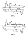
- FIG. 3 is a schematic diagram of a portion of the gas analyzer apparatus shown in FIG. 2 by the broken line oval designated Fig. 3 in FIG.;
- FIG. 4 is a schematic diagram as in FIG. 3 of the designated portion with the apparatus in another position.
- FIG. 1 is a schematic diagram of a gas analyzer apparatus 10 in accordance with an exemplary embodiment outside the scope of the present invention.
- the apparatus 10 comprises a device or platform 12 for supporting a predetermined quantity of a reagent capable of reacting with a predetermined gas to cause a change in a characteristic of the reagent, in this embodiment a color change of the reagent.
- the platform 12 is a transparent circular disk of glass which is rotatable stepwise by a motor 14 coupled to platform 12 by a shaft 16.
- a reservoir in this embodiment a cartridge 18, similar to an ink cartridge for an ink-jet printer, holds a quantity of reagent, and is sealed until installed in the apparatus 10.
- a dispenser 20 includes a reservoir receiving support portion 22 having a seal piercing member 24 and a seal, such as an O-ring 26, to seal the reservoir 18 to the support portion 22 against ambient air entering the reservoir and the dispenser 20.
- Dispenser 20 includes a conduit 28 integral with receiving portion 22 and leading to a drop dispenser 30 also integral with conduit 28.
- Drop dispenser 30, in this embodiment comprises a wire dispenser 32.
- Wire dispenser 32 has a solenoid 34 which upon activation causes the wire or ram 36 of the dispenser to raise to allow a predetermined quantity of reagent in conduit 28 to enter the space in conduit 28 normally closed and sealed by the wire 36 passing through conduit 28.
- the quantity of reagent in conduit 28 under the lower end of wire 36 is dispensed onto the platform 12.
- the wire 36 and the openings in the conduit 28 through which wire 36 passes are sized to admit and dispense a droplet of reagent onto the platform, whereas the wire 36 substantially seals the openings in the conduit when in the downward position.
- the position of the dispensed droplet of reagent on the platform is determined by rotation of the platform by the motor 14.
- the dispensed droplet of reagent is positioned in the path of a beam 38 from a coherent light source 40.
- Beam 38 passes through the droplet of reagent and through the transparent platform 12 to a photodetector or a microspectrometer 42 (e.g. a photodiode) which is electronically coupled to an electronics module 44.
- the electronic module 44 is adapted to generate a color change plot, denoted by reference numeral 46 in FIG. 1 .
- a predetermined gas which causes a reaction with the droplet of reagent, a change in the color of the reagent will occur and will be detected by the photodetector or microspectrometer and will be observable on the color change plot.
- FIGS. 2-4 illustrate schematically an examplary embodiment of the present invention, wherein elements which are identical to elements in the first embodiment shown in FIG. 1 , have the same reference numerals and are not explained further for the sake of brevity.
- the platform 52 is an elongated strip, instead of a disk as is platform 12 in the embodiment shown in FIG.1 .
- Platform 52 has a series of orifices 54 into which droplets of reagent are dispensed by the same apparatus as in the embodiment shown in FIG. 1 , and are held therein by capillary forces as explained above.
- platform 52 can be opaque or transparent, and if opaque can be of material, such as metals like gold alloy or platinum which do not react with the reagent. If platform 52 is transparent, it can be fashioned of the same materials as described herein for the first embodiment. Whereas in the first embodiment herein platform 12 was rotated by motor 14, in this embodiment platform 52 is moved reciprocally as indicated by arrow 56, by hand or by a motor and gears (not shown) in stepwise reciprocal fashion as is well known in the art. The platform 52 and the lower portion of dispenser 20 are enclosed by walls or a septum 58 with seals 60 ( FIGS. 3 and 4 ) to provide an enclosed, low-dead-volume sample stage 62 having a gas sample inlet 64 and a gas sample outlet 66.
- the droplet in the orifice is moved to the detecting position where the beam 38 passes through the droplet and a color change of the droplet will occur if a reaction with a predetermined gas and will be detected by the photodetector or microspectrometer 42 and the electronics module 44 coupled to the photodetector or microspectrometer 42.
- a color change plot (not shown) will be generated if a color change has occurred.
- FIG. 2 further illustrates an embodiment of this invention wherein reagent is removed from the orifices 54 in platform 50.
- the apparatus which performs the removal includes a second wire-piston 68, which can be identical to wire piston 32, by wire 70 passing through the orifice forcing the reagent out of the orifice and onto a disposable pad 72, which is subsequently removed from the analyzer as waste material and replaced.
- FIGS. 3 and 4 show an embodiment wherein both the dispensing of the droplet of reagent into an orifice 54 and the removal of a droplet from an orifice 54 is provided by the same drop dispenser 30, acting sequentially upon different orifices.
- the droplet of reagent is being dispensed into the orifice 54.
- the droplet in the orifice 54 is being detected for reaction with a sample of gas having entered into the septum 58 through inlet 64 by a beam of light 38 passing therethrough via openings or windows 74 and 76.
- a color change in the droplets of reagent can be detected by having the photodetector or microspectrometer 42 positioned on the same side of the platform as the droplets, (not shown), but an angle to the beam 38 and having the photodetector or microspectrometer read the color change in the droplet upon the reflection of the color of the droplets from the platform surface.
Landscapes
- Life Sciences & Earth Sciences (AREA)
- Health & Medical Sciences (AREA)
- Chemical & Material Sciences (AREA)
- Biochemistry (AREA)
- Biophysics (AREA)
- Molecular Biology (AREA)
- Physics & Mathematics (AREA)
- Analytical Chemistry (AREA)
- Dispersion Chemistry (AREA)
- General Health & Medical Sciences (AREA)
- General Physics & Mathematics (AREA)
- Immunology (AREA)
- Pathology (AREA)
- Investigating Or Analyzing Non-Biological Materials By The Use Of Chemical Means (AREA)
- Investigating Or Analysing Materials By The Use Of Chemical Reactions (AREA)
- Sampling And Sample Adjustment (AREA)
Claims (12)
- Appareil analyseur (10) de gaz comportant :a. une plate-forme réutilisable (12) sensiblement imperméable ;b. un réservoir (18) d'un réactif capable de réagir avec un gaz prédéterminé pour provoquer un changement détectable d'une caractéristique du réactif ;c. un distributeur (20) servant à distribuer une quantité régulée du réactif sous la forme d'une gouttelette en provenance du réservoir (18) directement sur et dans une position prédéterminé sur la plate-forme (12), la plate-forme (12) étant dotée d'au moins un orifice dimensionné de façon à maintenir la gouttelette par des forces capillaires ;d. une source optique (40) adjacente à la plate-forme imperméable (12), qui émet un faisceau de lumière (38) ; ete. un détecteur (42) de signature chimique qui détecte la présence du gaz prédéterminé à l'intérieur de la gouttelette sur la plate-forme en réponse à une réaction du gaz prédéterminé avec la quantité régulée de réactif pour provoquer un changement détectable d'une caractéristique du réactif et un changement d'une longueur d'onde du faisceau de lumière (38) traversant la gouttelette et détecté par le détecteur (42).
- Analyseur de gaz selon la revendication 1, la plate-forme réutilisable (12) étant transparente.
- Analyseur de gaz selon la revendication 1, la plate-forme (12) comportant un disque pivotant en matériau transparent.
- Analyseur de gaz selon la revendication 2, la plate-forme réutilisable transparente (12) étant choisie dans le groupe constitué du verre et d'un polymère transparent sensiblement imperméable.
- Analyseur de gaz selon la revendication 4, le polymère étant choisi dans le groupe constitué du chlorure de polyvinyle, du polyéthylène et du polytétrafluoroéthylène.
- Analyseur de gaz selon la revendication 1, le distributeur (20) étant un distributeur à piston en fil métallique.
- Analyseur de gaz selon la revendication 1, la plate-forme (12) comportant une pluralité d'orifices (54) formés dans celle-ci et dimensionnés de façon à retenir les gouttelettes dans les orifices par action capillaire.
- Analyseur de gaz selon la revendication 7, le distributeur (20) étant capable de distribuer une quantité régulée de réactif de la taille d'une goutte en provenance du réservoir (18) dans un ou plusieurs orifices de la pluralité d'orifices (54) de la plate-forme (12).
- Analyseur de gaz selon la revendication 1, comportant en outre un appareil (68) servant à évacuer des gouttelettes de réactif du ou des orifices (54).
- Analyseur de gaz selon la revendication 7, comportant en outre un appareil (68) servant à évacuer des gouttelettes de réactif des pluralités d'orifices (54) de la plate-forme (12).
- Procédé de détection d'un gaz, comportant les étapes consistant à :a. distribuer une quantité régulée d'un réactif sous la forme d'une gouttelette, capable de réagir avec un gaz prédéterminé pour provoquer un changement détectable d'une caractéristique du réactif, dans un orifice (54) prédéterminé d'une plate-forme réutilisable (12), et soutenir la gouttelette dans l'orifice par des forces capillaires ;b. faire passer un faisceau de lumière (38) à travers la gouttelette ; etc. détecter une réaction de la quantité régulée de réactif distribuée sur l'orifice prédéterminé de la plate-forme (12) avec le gaz prédéterminé par un changement d'une longueur d'onde du faisceau de lumière (38) traversant la gouttelette.
- Procédé selon la revendication 11, la gouttelette de réactif étant distribuée du réservoir (18) dans l'orifice (54) de la plate-forme (12).
Applications Claiming Priority (1)
| Application Number | Priority Date | Filing Date | Title |
|---|---|---|---|
| US11/762,891 US8003056B2 (en) | 2007-06-14 | 2007-06-14 | Gas analyzer apparatus and method of analyzing gases |
Publications (3)
| Publication Number | Publication Date |
|---|---|
| EP2012119A2 EP2012119A2 (fr) | 2009-01-07 |
| EP2012119A3 EP2012119A3 (fr) | 2010-12-15 |
| EP2012119B1 true EP2012119B1 (fr) | 2013-01-02 |
Family
ID=39863130
Family Applications (1)
| Application Number | Title | Priority Date | Filing Date |
|---|---|---|---|
| EP08252025A Ceased EP2012119B1 (fr) | 2007-06-14 | 2008-06-12 | Appareil et procédé d'analyse de gaz |
Country Status (4)
| Country | Link |
|---|---|
| US (1) | US8003056B2 (fr) |
| EP (1) | EP2012119B1 (fr) |
| CN (1) | CN101324549B (fr) |
| CA (1) | CA2635063A1 (fr) |
Families Citing this family (4)
| Publication number | Priority date | Publication date | Assignee | Title |
|---|---|---|---|---|
| WO2011112222A2 (fr) | 2009-12-15 | 2011-09-15 | Nomadics, Inc. | Système et procédé de détection multi-analytes |
| CN108459018B (zh) * | 2018-06-25 | 2023-11-28 | 中联品检(福建)检测服务有限公司 | 一种纺织物甲醛检测装置及检测方法 |
| CN109925979A (zh) * | 2019-04-24 | 2019-06-25 | 四川轻化工大学 | 管式气液界面反应器、管式化学发光检测装置及检测方法 |
| IL300255A (en) * | 2020-08-05 | 2023-03-01 | Ausmed Global Ltd | Test device with built-in liquid storage |
Citations (1)
| Publication number | Priority date | Publication date | Assignee | Title |
|---|---|---|---|---|
| EP1344565A1 (fr) * | 2002-03-13 | 2003-09-17 | The Automation Partnership (Cambridge) Limited | Distribution de gouttelettes à volume faible |
Family Cites Families (12)
| Publication number | Priority date | Publication date | Assignee | Title |
|---|---|---|---|---|
| US2602729A (en) * | 1941-10-30 | 1952-07-08 | Curry Manfred | Apparatus for determining the concentration of a chemically active gas in an atmosphere |
| GB1545572A (en) | 1977-01-28 | 1979-05-10 | Neotronics Ltd | Apparatus for sensing toxic gases |
| NL8400380A (nl) | 1984-02-07 | 1985-09-02 | Optische Ind De Oude Delft Nv | Inrichting voor het detecteren van kleurverschillen. |
| US4617277A (en) | 1984-03-23 | 1986-10-14 | The Babcock & Wilcox Company | Process and apparatus for monitoring ambient carbon monoxide |
| US4597778A (en) | 1984-10-22 | 1986-07-01 | Honeywell Inc. | Quasi-continuous sorption/desorption analysis method and an apparatus utilizing the same |
| DE3543324A1 (de) | 1985-12-07 | 1987-06-11 | Draegerwerk Ag | Verfahren zur messung von flaechigen verfaerbungszonen eines indikatortraegers und vorrichtung hierzu |
| DE3735176A1 (de) | 1987-10-17 | 1989-04-27 | Draegerwerk Ag | Dosimeter |
| US5091642A (en) | 1990-05-11 | 1992-02-25 | Mda Scientific, Inc. | Colorimetric detection apparatus |
| US5232664A (en) | 1991-09-18 | 1993-08-03 | Ventana Medical Systems, Inc. | Liquid dispenser |
| US6296702B1 (en) * | 1999-03-15 | 2001-10-02 | Pe Corporation (Ny) | Apparatus and method for spotting a substrate |
| US20040175837A1 (en) * | 2002-12-04 | 2004-09-09 | Ulrich Bonne | Compact opto-fluidic chemical sensor |
| TW200632314A (en) | 2004-12-07 | 2006-09-16 | Honeywell Analytics Ag | Gas detection method and system |
-
2007
- 2007-06-14 US US11/762,891 patent/US8003056B2/en active Active
-
2008
- 2008-06-12 EP EP08252025A patent/EP2012119B1/fr not_active Ceased
- 2008-06-13 CN CN2008101314782A patent/CN101324549B/zh not_active Expired - Fee Related
- 2008-06-13 CA CA002635063A patent/CA2635063A1/fr not_active Abandoned
Patent Citations (1)
| Publication number | Priority date | Publication date | Assignee | Title |
|---|---|---|---|---|
| EP1344565A1 (fr) * | 2002-03-13 | 2003-09-17 | The Automation Partnership (Cambridge) Limited | Distribution de gouttelettes à volume faible |
Also Published As
| Publication number | Publication date |
|---|---|
| CN101324549A (zh) | 2008-12-17 |
| EP2012119A3 (fr) | 2010-12-15 |
| US20080311663A1 (en) | 2008-12-18 |
| EP2012119A2 (fr) | 2009-01-07 |
| US8003056B2 (en) | 2011-08-23 |
| CA2635063A1 (fr) | 2008-12-14 |
| CN101324549B (zh) | 2011-07-27 |
Similar Documents
| Publication | Publication Date | Title |
|---|---|---|
| JP5686744B2 (ja) | 自動分析装置 | |
| US7295308B1 (en) | Air sampling method and sensor system for spectroscopic detection and identification of chemical and biological contaminants | |
| EP2877833B1 (fr) | Analyse d'eau mobile | |
| EP0046087B1 (fr) | Procédé et dispositif d'analyse chimique | |
| US7465427B2 (en) | Apparatus, system, and method of detecting an analyte utilizing pyroelectric technology | |
| US8003056B2 (en) | Gas analyzer apparatus and method of analyzing gases | |
| KR20010020145A (ko) | 분석 시스템 | |
| US20050118074A1 (en) | Methods and devices for storing and dispensing liquids | |
| EP2876449A1 (fr) | Dispositif d'analyse automatique | |
| EP2295986A2 (fr) | Analyseur automatique avec une cartouche de réactifs pour un auto-test | |
| JP2004536303A (ja) | 目標物質を検出するためのシステム及び方法 | |
| EP0677744B1 (fr) | Procédé et appareil pour déposer des échantillons liquides sur des éléments d'analyse secs | |
| EP0042337B1 (fr) | Procédé et dispositif de distribution de doses de fluides biologiques | |
| EP2075587B1 (fr) | Analyseur automatique et son procédé de distribution | |
| JP4604109B2 (ja) | 試料検査のための手持ち式分析装置 | |
| WO1992015863A1 (fr) | Bande de test amelioree | |
| WO2021079645A1 (fr) | Dispositif d'analyse automatique et procédé de distribution de réactif | |
| CA2863506A1 (fr) | Procede et appareil d'analyse rapide haute sensibilite d'echantillons de faible volume de matieres biologiques | |
| JP3268400B2 (ja) | 混合反応装置 | |
| EP3341707B1 (fr) | Détection de substance | |
| CN114113649A (zh) | 一种转盘装置及免疫分析仪 | |
| JP7539547B2 (ja) | 自動分析装置、および検体の分注方法 | |
| JP2005009866A (ja) | 分析装置における情報読み取り機 | |
| LU501663B1 (en) | Method for determining a function for determining a volume of liquid to be dispensed | |
| WO2024237046A1 (fr) | Dispositif d'analyse automatique et procédé de réglage de temporisation |
Legal Events
| Date | Code | Title | Description |
|---|---|---|---|
| PUAI | Public reference made under article 153(3) epc to a published international application that has entered the european phase |
Free format text: ORIGINAL CODE: 0009012 |
|
| AK | Designated contracting states |
Kind code of ref document: A2 Designated state(s): AT BE BG CH CY CZ DE DK EE ES FI FR GB GR HR HU IE IS IT LI LT LU LV MC MT NL NO PL PT RO SE SI SK TR |
|
| AX | Request for extension of the european patent |
Extension state: AL BA MK RS |
|
| PUAL | Search report despatched |
Free format text: ORIGINAL CODE: 0009013 |
|
| AK | Designated contracting states |
Kind code of ref document: A3 Designated state(s): AT BE BG CH CY CZ DE DK EE ES FI FR GB GR HR HU IE IS IT LI LT LU LV MC MT NL NO PL PT RO SE SI SK TR |
|
| AX | Request for extension of the european patent |
Extension state: AL BA MK RS |
|
| 17P | Request for examination filed |
Effective date: 20101126 |
|
| 17Q | First examination report despatched |
Effective date: 20110526 |
|
| AKX | Designation fees paid |
Designated state(s): DE FR GB |
|
| GRAP | Despatch of communication of intention to grant a patent |
Free format text: ORIGINAL CODE: EPIDOSNIGR1 |
|
| GRAS | Grant fee paid |
Free format text: ORIGINAL CODE: EPIDOSNIGR3 |
|
| GRAA | (expected) grant |
Free format text: ORIGINAL CODE: 0009210 |
|
| AK | Designated contracting states |
Kind code of ref document: B1 Designated state(s): DE FR GB |
|
| REG | Reference to a national code |
Ref country code: GB Ref legal event code: FG4D |
|
| REG | Reference to a national code |
Ref country code: DE Ref legal event code: R096 Ref document number: 602008021313 Country of ref document: DE Effective date: 20130228 |
|
| PLBE | No opposition filed within time limit |
Free format text: ORIGINAL CODE: 0009261 |
|
| STAA | Information on the status of an ep patent application or granted ep patent |
Free format text: STATUS: NO OPPOSITION FILED WITHIN TIME LIMIT |
|
| 26N | No opposition filed |
Effective date: 20131003 |
|
| REG | Reference to a national code |
Ref country code: DE Ref legal event code: R097 Ref document number: 602008021313 Country of ref document: DE Effective date: 20131003 |
|
| REG | Reference to a national code |
Ref country code: FR Ref legal event code: PLFP Year of fee payment: 9 |
|
| REG | Reference to a national code |
Ref country code: FR Ref legal event code: PLFP Year of fee payment: 10 |
|
| REG | Reference to a national code |
Ref country code: FR Ref legal event code: PLFP Year of fee payment: 11 |
|
| PGFP | Annual fee paid to national office [announced via postgrant information from national office to epo] |
Ref country code: GB Payment date: 20220621 Year of fee payment: 15 |
|
| PGFP | Annual fee paid to national office [announced via postgrant information from national office to epo] |
Ref country code: FR Payment date: 20220623 Year of fee payment: 15 |
|
| PGFP | Annual fee paid to national office [announced via postgrant information from national office to epo] |
Ref country code: DE Payment date: 20220628 Year of fee payment: 15 |
|
| REG | Reference to a national code |
Ref country code: DE Ref legal event code: R119 Ref document number: 602008021313 Country of ref document: DE |
|
| GBPC | Gb: european patent ceased through non-payment of renewal fee |
Effective date: 20230612 |
|
| PG25 | Lapsed in a contracting state [announced via postgrant information from national office to epo] |
Ref country code: DE Free format text: LAPSE BECAUSE OF NON-PAYMENT OF DUE FEES Effective date: 20240103 Ref country code: GB Free format text: LAPSE BECAUSE OF NON-PAYMENT OF DUE FEES Effective date: 20230612 |
|
| PG25 | Lapsed in a contracting state [announced via postgrant information from national office to epo] |
Ref country code: FR Free format text: LAPSE BECAUSE OF NON-PAYMENT OF DUE FEES Effective date: 20230630 |