EP2012139A1 - Body monitoring apparatus and method - Google Patents
Body monitoring apparatus and method Download PDFInfo
- Publication number
- EP2012139A1 EP2012139A1 EP07111887A EP07111887A EP2012139A1 EP 2012139 A1 EP2012139 A1 EP 2012139A1 EP 07111887 A EP07111887 A EP 07111887A EP 07111887 A EP07111887 A EP 07111887A EP 2012139 A1 EP2012139 A1 EP 2012139A1
- Authority
- EP
- European Patent Office
- Prior art keywords
- skin
- pulses
- distance
- antenna
- generator
- Prior art date
- Legal status (The legal status is an assumption and is not a legal conclusion. Google has not performed a legal analysis and makes no representation as to the accuracy of the status listed.)
- Withdrawn
Links
Images


Classifications
-
- G—PHYSICS
- G01—MEASURING; TESTING
- G01S—RADIO DIRECTION-FINDING; RADIO NAVIGATION; DETERMINING DISTANCE OR VELOCITY BY USE OF RADIO WAVES; LOCATING OR PRESENCE-DETECTING BY USE OF THE REFLECTION OR RERADIATION OF RADIO WAVES; ANALOGOUS ARRANGEMENTS USING OTHER WAVES
- G01S13/00—Systems using the reflection or reradiation of radio waves, e.g. radar systems; Analogous systems using reflection or reradiation of waves whose nature or wavelength is irrelevant or unspecified
- G01S13/66—Radar-tracking systems; Analogous systems
- G01S13/70—Radar-tracking systems; Analogous systems for range tracking only
-
- A—HUMAN NECESSITIES
- A61—MEDICAL OR VETERINARY SCIENCE; HYGIENE
- A61B—DIAGNOSIS; SURGERY; IDENTIFICATION
- A61B5/00—Measuring for diagnostic purposes; Identification of persons
- A61B5/05—Detecting, measuring or recording for diagnosis by means of electric currents or magnetic fields; Measuring using microwaves or radio waves
- A61B5/0507—Detecting, measuring or recording for diagnosis by means of electric currents or magnetic fields; Measuring using microwaves or radio waves using microwaves or terahertz waves
-
- A—HUMAN NECESSITIES
- A61—MEDICAL OR VETERINARY SCIENCE; HYGIENE
- A61B—DIAGNOSIS; SURGERY; IDENTIFICATION
- A61B5/00—Measuring for diagnostic purposes; Identification of persons
- A61B5/103—Measuring devices for testing the shape, pattern, colour, size or movement of the body or parts thereof, for diagnostic purposes
- A61B5/11—Measuring movement of the entire body or parts thereof, e.g. head or hand tremor or mobility of a limb
- A61B5/113—Measuring movement of the entire body or parts thereof, e.g. head or hand tremor or mobility of a limb occurring during breathing
-
- G—PHYSICS
- G01—MEASURING; TESTING
- G01S—RADIO DIRECTION-FINDING; RADIO NAVIGATION; DETERMINING DISTANCE OR VELOCITY BY USE OF RADIO WAVES; LOCATING OR PRESENCE-DETECTING BY USE OF THE REFLECTION OR RERADIATION OF RADIO WAVES; ANALOGOUS ARRANGEMENTS USING OTHER WAVES
- G01S13/00—Systems using the reflection or reradiation of radio waves, e.g. radar systems; Analogous systems using reflection or reradiation of waves whose nature or wavelength is irrelevant or unspecified
- G01S13/02—Systems using reflection of radio waves, e.g. primary radar systems; Analogous systems
- G01S13/06—Systems determining position data of a target
- G01S13/08—Systems for measuring distance only
- G01S13/10—Systems for measuring distance only using transmission of interrupted, pulse modulated waves
- G01S13/18—Systems for measuring distance only using transmission of interrupted, pulse modulated waves wherein range gates are used
-
- G—PHYSICS
- G01—MEASURING; TESTING
- G01S—RADIO DIRECTION-FINDING; RADIO NAVIGATION; DETERMINING DISTANCE OR VELOCITY BY USE OF RADIO WAVES; LOCATING OR PRESENCE-DETECTING BY USE OF THE REFLECTION OR RERADIATION OF RADIO WAVES; ANALOGOUS ARRANGEMENTS USING OTHER WAVES
- G01S13/00—Systems using the reflection or reradiation of radio waves, e.g. radar systems; Analogous systems using reflection or reradiation of waves whose nature or wavelength is irrelevant or unspecified
- G01S13/02—Systems using reflection of radio waves, e.g. primary radar systems; Analogous systems
- G01S13/50—Systems of measurement based on relative movement of target
- G01S13/58—Velocity or trajectory determination systems; Sense-of-movement determination systems
- G01S13/581—Velocity or trajectory determination systems; Sense-of-movement determination systems using transmission of interrupted pulse modulated waves and based upon the Doppler effect resulting from movement of targets
-
- A—HUMAN NECESSITIES
- A61—MEDICAL OR VETERINARY SCIENCE; HYGIENE
- A61B—DIAGNOSIS; SURGERY; IDENTIFICATION
- A61B5/00—Measuring for diagnostic purposes; Identification of persons
- A61B5/02—Detecting, measuring or recording for evaluating the cardiovascular system, e.g. pulse, heart rate, blood pressure or blood flow
- A61B5/024—Measuring pulse rate or heart rate
-
- G—PHYSICS
- G01—MEASURING; TESTING
- G01S—RADIO DIRECTION-FINDING; RADIO NAVIGATION; DETERMINING DISTANCE OR VELOCITY BY USE OF RADIO WAVES; LOCATING OR PRESENCE-DETECTING BY USE OF THE REFLECTION OR RERADIATION OF RADIO WAVES; ANALOGOUS ARRANGEMENTS USING OTHER WAVES
- G01S13/00—Systems using the reflection or reradiation of radio waves, e.g. radar systems; Analogous systems using reflection or reradiation of waves whose nature or wavelength is irrelevant or unspecified
- G01S13/02—Systems using reflection of radio waves, e.g. primary radar systems; Analogous systems
- G01S13/0209—Systems with very large relative bandwidth, i.e. larger than 10 %, e.g. baseband, pulse, carrier-free, ultrawideband
Definitions
- the present invention concerns, in general, the medical field and more particularly a monitor and a method for detecting, monitoring and measuring the movements of internal body organs, such as heart, lungs, foetus, womb, etc.
- the present invention relates to a monitor and a method, as mentioned above, making use of an impulse radar system and comprising means to compensate for the movements as a whole of the body under monitoring.
- U.S. Patent No. 5,573,012 An impulse radar system for monitoring internal body organs is described in U.S. Patent No. 5,573,012 and its continuation in part U.S. Patent No. 5,766,208 .
- UWB radar consisting of an UWB (Ultra Wide Band) impulse transmitter (made of a "Pseudo Random Binary Sequence" -or PBRS- generator 100, a pulse generator 101 and a transmit antenna 102), and an UWB pulse receiver comprising a receive antenna 106 and a boxcar averager (made of a voltage controlled delay generator 113, a reference level circuit 112 and a sampler and averager 114), synchronously locked to the emitted pulses with a phase shift proportional to the time delay of the pulse-echo path to the body organ (for instance the heart) wall to be tracked.
- UWB radar consisting of an UWB (Ultra Wide Band) impulse transmitter (made of a "Pseudo Random Binary Sequence" -
- the voltage controlled delay generator receives PRBS pulses as well as a fixed delay provided by reference level circuit 112 from which it generates a sampling window (or time gating pulse) that corresponds to the measuring range of the target echo signal. No compensation is provided for the movement of the entire body so that, if the body moves, tracking of the heart wall, or of any other internal organ of interest, is extremely difficult to achieve due to the additional noise (i.e. artefacts), which is introduced into the useful signal by body movement or even impossible to achieve if, for the same reason, the echo signal arrives outside the fixed sampling window.
- additional noise i.e. artefacts
- the system of the invention includes a skin echo detector that continuously detects and permits to compensate for the variations in the distance between the skin and the system antennas.
- the radar system also captures the early echo from the air-skin interface and makes use of it to estimate the distance to the body in real time and to adjust the time gating pulse accordingly.
- the skin echo detector adjusts the delay of the voltage controlled delay generator to correspond to the correct distance between the antennas and the body so as to maintain the tracking on the internal body organ wall of interest.
- the antenna-skin distance is estimated by detecting the skin echo, which is a very intense and early echo returning from the body.
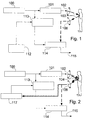
- Fig. 2 shows a block diagram of a radar system in accordance with the principle of the present invention.
- the system of the invention provides a skin echo detector 117.
- the echo signal from the receive antenna 106 is supplied to such echo detector 117 and the latter applies its output signal, which is a function of the path 104 between the skin and antennas (102 and 106), to the control input of the controlled delay generator 113 so as to adjust the range gate, i.e. the sampling window for the sampler and averager 114. This adjustment will take care of the instantaneous distance between the antennas and the body.
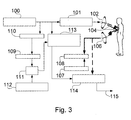
- FIG. 3 shows a first embodiment of the invention.
- the PRBS (Pseudo Random Binary Sequence) generator 100 produces a sequence of pulses with random varying interpulse period.
- the pulse sequence is made random - or pseudo-random - essentially for eliminating interference from other near RF (radio frequency) sources.
- the pulses are applied to the pulse generator 101 for producing UWB pulses (i.e. pulses of very short duration leading to a wide spectrum emitted radiation) to be radiated by the antenna 102. From the antenna the pulses can run on two paths.
- the shorter path 104 comprises skin reflection, while the longer path 103 considers penetration into the human body and reflection by the heart wall 105 (or any other internal organ of interest to be monitored). So the receiving antenna 106 will receive one very intense and early echo from the skin reflection and a subsequent weaker echo from the internal organ wall reflection.
- a skin echo detector is composed by a comparator 108, which outputs a signal when whatsoever echo signal is higher than a predefined reference voltage level supplied by a second reference level circuit 107.
- the output signal of the comparator samples the voltage level provided by the ramp generator 110 by means of the sample-and-hold circuit 109.
- This sampled voltage being proportional to the instantaneous distance between the skin and the antennas 102 and 106, is added by the adder 111 to a first reference voltage level provided by a first reference level circuit 112 for calibration, so that the resulting voltage is made directly proportional to the instantaneous distance of the heart wall to the antennas 102 and 106.
- This latter voltage is used to control the voltage controlled delay generator 113 for the operation of a boxcar averager, made of the sampler and averager circuit 114, to produce a final output signal 115.
- This final output signal is only proportional to the antenna-heart distance and will be further processed by processing means (not shown), such as a computer and display devices.
- Compensation of body movements is thus continuously made by the skin echo detector, so as to adapt the voltage controlled delay generator to the exact distance of the internal organ wall to the two antennas.
- Relative distance of the body organ wall to the skin is adjusted by varying the first reference voltage level of circuit 112 while relative distance of the skin to the antennas is controlled by the second reference voltage level 107.
- the ramp voltage signal out of the ramp generator is continuously reset to zero at each PRBS generator pulse.
- the first reference voltage level 112 can be negative so as to compensate even for excessive delay in response to the output signal of the comparator 108 which might happen even after the echo from the heart wall has arrived. In such a case, compensation will be effective on subsequent pulses, provided that the speed of movement of the body is very low with respect to the repetition frequency of pulses generated by the PRBS generator 100.
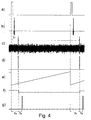
- Fig. 4 shows the different waveforms, which appear in the impulse radar system of Fig. 3 .
- Fig. 4.a shows PRBS pulses, as provided by PRBS generator 100. Typically, the average repetition frequency of these pulses is in the range of 1 to 10 MHz.
- Fig. 4.b shows UWB pulses generated by the pulse generator 101 from the pulses delivered by PRBS generator. As mentioned above, these pulses must have a short duration to cause the spectrum of the emitted radiation to be very large.
- Fig. 4.c shows the echo signal, as received by the receive antenna 106, which is applied to both the comparator circuit 108 and the sampler and averager circuit 114.
- the echo signal is strongly affected by noise except for peaks, which correspond to the echo signal from the skin surface and the amplitude of which is higher than the reference threshold voltage Tr that is used by the comparator circuit.
- the output signal of the comparator circuit shown in Fig. 4.d , is applied to the sample-and-hold circuit 109, which also receives the ramp voltage signal, shown in Fig. 4.e , delivered by the ramp generator 110. It must be noted that the ramp generator is reset by pulses generated by the PRBS generator 100.
- Fig. 4.f shows the output signal of circuit 109.
- the latency Ta between PRBS pulses and the signal of Fig. 4.f is representative of the distance between the skin and the antennas.
- a constant delay Tb given by the first reference level circuit 112 is added to Ta by the adder circuit 111 to generate a signal, shown in Fig. 4.g , which is applied to the voltage controlled delay generator 113.
- the latter can thus generate the sampling window for the target echo to be extracted by the sampler-and-averager circuit 114 from the echo signal ( Fig. 4.c ).
- Figure 5 shows a second embodiment of the present invention.
- the impulse radar system comprises the UWB pulse transmitter, as previously described, and a UWB pulse receiver consisting of a boxcar averager 114, synchronously locked to the emitted pulse with a phase shift, proportional to the time delay to the pulse-echo path to the heart (or lung) wall to be tracked.
- a skin echo detector has been added so as to detect in a continuous way and compensate for the variation in skin-antennas distance as follows:
- the skin echo detector of this second embodiment comprises a peak detector 116, the maximum amplitude of which is roughly proportional to the distance between the antenna and the skin of the patient, since the skin echo is supposed to be, not only the earliest echo signal but the one of the highest intensity.
- the signal out of the peak detector is adjusted to the correct compensation value, for the voltage controlled generator 113, by means of adder 111, which adds the output signal of said peak detector to the first reference voltage level provided by circuit 112.
- the resulting voltage is used to control the voltage controlled delay generator 113 for the operation of the boxcar averager, made of the sampler and averager circuit 114, to produce the final signal 115 out. This will only be proportional to the antennas-heart distance or M-mode heart wall signal.
- Fig. 6 shows the waveforms appearing at different points of the system of Fig. 5 .
- Figs. 6.a, 6.b and 6.c are identical to Figs. 4.a, 4.b and 4.c and therefore, will not be described again.
- Fig. 6.d shows a signal generated by the peak detector 116 and Fig. 6.e shows the output signal of this peak detector.
- the signal shown in Fig. 6.e exhibits a shift Ta with respect to PRBS pulses. Such shift corresponds to the path in the air between both antennas and the skin.
- an additional constant shift Tb is added to the delay Ta through the first reference level circuit 112 and the adder circuit 111.
- the output signal of the adder circuit is applied to the voltage controlled delay generator, which delivers an output signal shown in Fig. 6.f to the sampler-and-averager circuit 114.
- the signal produced by the latter circuit may be further processed by means known to anybody skilled in the art.
- FIG. 7 A possible implementation of the skin echo detector 117 of the first embodiment is shown in Figure 7 .
- the output of comparator 303 drives the sample-and-hold circuit 304 (made of the switch S1 and capacitor C2 [1.8nF]), which samples the ramp signal generated by the ramp generator 110.
- the latter comprises a constant current source 301 (transistor Q1 [PN3640] and resistors R1 [680 ⁇ ], R2 [82 ⁇ ], R3 [3.9k ⁇ ] and R5 [150 ⁇ ]) and a capacitor C1 [1.8nF].
- the output of sample-and-hold circuit 304 is added to the first reference level provided by circuit 305 (adjustable resistor VR1 [10k ⁇ ] and resistor R8 [1k ⁇ ]).
- the resulting signal is applied to the non-inverting input of the amplifier 306 [LM6132B].
- the ramp generator 110 is periodically reset by pulses from the PRBS generator through N-MOS transistor Q2 [BSH101]. When activated, the transistor Q2 rapidly discharges the capacitor C1, thus resetting said ramp generator.
- the output signal Vout can then drive the Voltage Controlled Delay Generator of Figure 3 .
- FIG. 8 Another implementation of the skin echo detector according to the second embodiment of the invention is shown in Figure 8 .
- Circuit 310 comprises an operational amplifier X2 [LM6132B] and a Schottky diode D1 [BAT85]. Schottky diodes are known to exhibit a very low direct voltage drop and a very fast switching time. The time constant of the circuit arrangement 311 is large enough, so that the voltage at the common node of capacitor C3 and resistor R10 is always above the noise level of the echo signal within the repetition period. As in figure 7 , the output signal of the peak detector is added to the second reference level provided by circuit 305 and the resulting signal is amplified by the amplifier 306.
- Exemplary applications of the present invention may include, without any limitation
Landscapes
- Engineering & Computer Science (AREA)
- Radar, Positioning & Navigation (AREA)
- Remote Sensing (AREA)
- Health & Medical Sciences (AREA)
- Life Sciences & Earth Sciences (AREA)
- Physics & Mathematics (AREA)
- Computer Networks & Wireless Communication (AREA)
- General Physics & Mathematics (AREA)
- Biomedical Technology (AREA)
- Animal Behavior & Ethology (AREA)
- Biophysics (AREA)
- Pathology (AREA)
- Veterinary Medicine (AREA)
- Heart & Thoracic Surgery (AREA)
- Medical Informatics (AREA)
- Molecular Biology (AREA)
- Surgery (AREA)
- Public Health (AREA)
- General Health & Medical Sciences (AREA)
- Radiology & Medical Imaging (AREA)
- Nuclear Medicine, Radiotherapy & Molecular Imaging (AREA)
- Physiology (AREA)
- Dentistry (AREA)
- Oral & Maxillofacial Surgery (AREA)
- Radar Systems Or Details Thereof (AREA)
Abstract
The present invention concerns a monitor and a method for detecting, monitoring and measuring the movement of internal body organs, such as heart, lungs, foetus, womb, etc.
The monitor comprises an Ultra Wide Band impulse transmitter, consisting of a Pseudo Random Binary Sequence generator (100), a pulse generator (101) and a transmit antenna (102), and an UWB pulse receiver, consisting of a receive antenna (106) and a boxcar averager made of a voltage controlled delay generator (113), a reference level circuit (112) and a sampler-and-averager (114). The latter is synchronously locked to the emitted pulses with a phase shift proportional to the distance between the antennas and the body organ wall to be monitored. According to the present invention, there is also provided a skin echo detector (117) for continuously determining the distance between the antennas and the skin of the patient and using it to adjust the delay of the voltage controlled delay generator to permit the latter to compensate in real time for the movements of the body.
Description
- The present invention concerns, in general, the medical field and more particularly a monitor and a method for detecting, monitoring and measuring the movements of internal body organs, such as heart, lungs, foetus, womb, etc.
- More precisely, the present invention relates to a monitor and a method, as mentioned above, making use of an impulse radar system and comprising means to compensate for the movements as a whole of the body under monitoring.
- An impulse radar system for monitoring internal body organs is described in
U.S. Patent No. 5,573,012 and its continuation in partU.S. Patent No. 5,766,208 . These patents disclose (seeFig.1 of USP '012) an UWB radar consisting of an UWB (Ultra Wide Band) impulse transmitter (made of a "Pseudo Random Binary Sequence" -or PBRS-generator 100, apulse generator 101 and a transmit antenna 102), and an UWB pulse receiver comprising a receiveantenna 106 and a boxcar averager (made of a voltage controlleddelay generator 113, areference level circuit 112 and a sampler and averager 114), synchronously locked to the emitted pulses with a phase shift proportional to the time delay of the pulse-echo path to the body organ (for instance the heart) wall to be tracked. The voltage controlled delay generator receives PRBS pulses as well as a fixed delay provided byreference level circuit 112 from which it generates a sampling window (or time gating pulse) that corresponds to the measuring range of the target echo signal. No compensation is provided for the movement of the entire body so that, if the body moves, tracking of the heart wall, or of any other internal organ of interest, is extremely difficult to achieve due to the additional noise (i.e. artefacts), which is introduced into the useful signal by body movement or even impossible to achieve if, for the same reason, the echo signal arrives outside the fixed sampling window. - The prior art known in August 1994 has been extensively reviewed in the above-mentioned U.S. Patents. Other developments of - or improvements to - this technique may be found in the following documents:
U.S. Patent 5,345,471 ,EP 694 235 WO 04/ 057 367 - When using the apparatuses described in
U.S. Patent 5,573,012 andU.S. Patent 5,766,208 , the tracking of internal organ movement is greatly hampered by the movements of the body as a whole. With apparatuses of this prior art, either the system should be fixed on the body in order to maintain constant the distance between transmit and receive antennas and the body, or the body has to be kept still. In some applications, such constraints may prove to be insufferable. - So, there is still a need for a new radar system which is capable of detecting, monitoring and measuring the movement of intra-body organs and to operate, on one hand, without any contact with the body of the patient and, on the other hand, even if the body is moving with respect to said radar system.
- Accordingly, it is an object of the present invention to provide a sensing device, which overcomes the above-mentioned drawbacks of prior art systems.
- It is another object of the present invention to provide a body monitoring apparatus and method, which is able to operate without any contact between the apparatus and the body.
- It is still another object of the invention to provide a new impulse radar system, which is capable of detecting, monitoring and measuring intra-body movements without being limited by the movements of the body itself with respect to the radar system.
- Briefly, the above and further objects and advantages of the present invention are realised by a new impulse radar system for detecting, monitoring and imaging internal body organs, which exhibits an intrinsic robustness with respect to the whole body movement. More specifically, the system of the invention includes a skin echo detector that continuously detects and permits to compensate for the variations in the distance between the skin and the system antennas. Actually, besides receiving echoes from internal body organs under monitoring, the radar system also captures the early echo from the air-skin interface and makes use of it to estimate the distance to the body in real time and to adjust the time gating pulse accordingly.
- The skin echo detector adjusts the delay of the voltage controlled delay generator to correspond to the correct distance between the antennas and the body so as to maintain the tracking on the internal body organ wall of interest. The antenna-skin distance is estimated by detecting the skin echo, which is a very intense and early echo returning from the body.
- In the following description, identical components in various figures will be designated by the same reference numbers.
- The above and other features of the present invention and the manner of obtaining them will become apparent, and the invention itself will be best understood, by reference to the following description and the accompanying drawings, wherein:
-
FIG. 1 is a block diagram of the body monitoring and imaging apparatus of the prior art; -
FIG. 2 shows a block diagram of a radar system according to the principle of the present invention; -
FIG. 3 shows a block diagram of a first embodiment of the present invention; -
FIG. 4 shows a timing diagram of the embodiment ofFig. 3 ; -
FIG. 5 shows a block diagram of a second embodiment of the present invention; -
FIG. 6 shows a timing diagram of the embodiment ofFig. 5 ; -
FIG. 7 shows an implementation of the skin detector of said first embodiment; and -
FIG. 8 shows an implementation of the skin detector of said second embodiment. -
Fig. 2 shows a block diagram of a radar system in accordance with the principle of the present invention. Contrary to the prior art radar system in which the controlleddelay generator 113 is controlled by a reference level circuit 112 (seeFig. 1 ), which gives a fixed value for establishing a fixed detection range, the system of the invention provides askin echo detector 117. The echo signal from thereceive antenna 106 is supplied tosuch echo detector 117 and the latter applies its output signal, which is a function of thepath 104 between the skin and antennas (102 and 106), to the control input of the controlleddelay generator 113 so as to adjust the range gate, i.e. the sampling window for the sampler andaverager 114. This adjustment will take care of the instantaneous distance between the antennas and the body. -
Figure 3 shows a first embodiment of the invention. The PRBS (Pseudo Random Binary Sequence)generator 100 produces a sequence of pulses with random varying interpulse period. The pulse sequence is made random - or pseudo-random - essentially for eliminating interference from other near RF (radio frequency) sources. The pulses are applied to thepulse generator 101 for producing UWB pulses (i.e. pulses of very short duration leading to a wide spectrum emitted radiation) to be radiated by theantenna 102. From the antenna the pulses can run on two paths. Theshorter path 104 comprises skin reflection, while thelonger path 103 considers penetration into the human body and reflection by the heart wall 105 (or any other internal organ of interest to be monitored). So the receivingantenna 106 will receive one very intense and early echo from the skin reflection and a subsequent weaker echo from the internal organ wall reflection. - A skin echo detector is composed by a
comparator 108, which outputs a signal when whatsoever echo signal is higher than a predefined reference voltage level supplied by a secondreference level circuit 107. The output signal of the comparator samples the voltage level provided by theramp generator 110 by means of the sample-and-hold circuit 109. This sampled voltage, being proportional to the instantaneous distance between the skin and theantennas adder 111 to a first reference voltage level provided by a firstreference level circuit 112 for calibration, so that the resulting voltage is made directly proportional to the instantaneous distance of the heart wall to theantennas delay generator 113 for the operation of a boxcar averager, made of the sampler andaverager circuit 114, to produce afinal output signal 115. This final output signal is only proportional to the antenna-heart distance and will be further processed by processing means (not shown), such as a computer and display devices. - Compensation of body movements is thus continuously made by the skin echo detector, so as to adapt the voltage controlled delay generator to the exact distance of the internal organ wall to the two antennas. Relative distance of the body organ wall to the skin is adjusted by varying the first reference voltage level of
circuit 112 while relative distance of the skin to the antennas is controlled by the secondreference voltage level 107. The ramp voltage signal out of the ramp generator is continuously reset to zero at each PRBS generator pulse. - It is important to note that the first
reference voltage level 112 can be negative so as to compensate even for excessive delay in response to the output signal of thecomparator 108 which might happen even after the echo from the heart wall has arrived. In such a case, compensation will be effective on subsequent pulses, provided that the speed of movement of the body is very low with respect to the repetition frequency of pulses generated by thePRBS generator 100. -
Fig. 4 shows the different waveforms, which appear in the impulse radar system ofFig. 3 .Fig. 4.a shows PRBS pulses, as provided by PRBSgenerator 100. Typically, the average repetition frequency of these pulses is in the range of 1 to 10 MHz.Fig. 4.b shows UWB pulses generated by thepulse generator 101 from the pulses delivered by PRBS generator. As mentioned above, these pulses must have a short duration to cause the spectrum of the emitted radiation to be very large.Fig. 4.c shows the echo signal, as received by thereceive antenna 106, which is applied to both thecomparator circuit 108 and the sampler andaverager circuit 114. As shown, the echo signal is strongly affected by noise except for peaks, which correspond to the echo signal from the skin surface and the amplitude of which is higher than the reference threshold voltage Tr that is used by the comparator circuit. The output signal of the comparator circuit, shown inFig. 4.d , is applied to the sample-and-hold circuit 109, which also receives the ramp voltage signal, shown inFig. 4.e , delivered by theramp generator 110. It must be noted that the ramp generator is reset by pulses generated by thePRBS generator 100.Fig. 4.f shows the output signal ofcircuit 109. The latency Ta between PRBS pulses and the signal ofFig. 4.f is representative of the distance between the skin and the antennas. In order to take into account the distance between the skin and the organ surface under monitoring, a constant delay Tb, given by the firstreference level circuit 112, is added to Ta by theadder circuit 111 to generate a signal, shown inFig. 4.g , which is applied to the voltage controlleddelay generator 113. As already mentioned, the latter can thus generate the sampling window for the target echo to be extracted by the sampler-and-averager circuit 114 from the echo signal (Fig. 4.c ). -
Figure 5 shows a second embodiment of the present invention. Like in the first embodiment, the impulse radar system comprises the UWB pulse transmitter, as previously described, and a UWB pulse receiver consisting of aboxcar averager 114, synchronously locked to the emitted pulse with a phase shift, proportional to the time delay to the pulse-echo path to the heart (or lung) wall to be tracked. According to the invention, a skin echo detector has been added so as to detect in a continuous way and compensate for the variation in skin-antennas distance as follows: - The skin echo detector of this second embodiment comprises a
peak detector 116, the maximum amplitude of which is roughly proportional to the distance between the antenna and the skin of the patient, since the skin echo is supposed to be, not only the earliest echo signal but the one of the highest intensity. The signal out of the peak detector is adjusted to the correct compensation value, for the voltage controlledgenerator 113, by means ofadder 111, which adds the output signal of said peak detector to the first reference voltage level provided bycircuit 112. The resulting voltage is used to control the voltage controlleddelay generator 113 for the operation of the boxcar averager, made of the sampler andaverager circuit 114, to produce thefinal signal 115 out. This will only be proportional to the antennas-heart distance or M-mode heart wall signal. -
Fig. 6 shows the waveforms appearing at different points of the system ofFig. 5 .Figs. 6.a, 6.b and 6.c are identical toFigs. 4.a, 4.b and 4.c and therefore, will not be described again.Fig. 6.d shows a signal generated by thepeak detector 116 andFig. 6.e shows the output signal of this peak detector. As for the first embodiment, the signal shown inFig. 6.e exhibits a shift Ta with respect to PRBS pulses. Such shift corresponds to the path in the air between both antennas and the skin. In order to take into account the distance between the skin and the organ under monitoring, an additional constant shift Tb is added to the delay Ta through the firstreference level circuit 112 and theadder circuit 111. The output signal of the adder circuit is applied to the voltage controlled delay generator, which delivers an output signal shown inFig. 6.f to the sampler-and-averager circuit 114. As mentioned with respect to the first embodiment, the signal produced by the latter circuit may be further processed by means known to anybody skilled in the art. - A possible implementation of the
skin echo detector 117 of the first embodiment is shown inFigure 7 . The signal Vin coming from the receivingantenna 106, after an amplification step which is not shown for sake of clarity, is compared by comparator 303 [ref. LT1720] with a second reference level circuit 302 (made of an adjustable resistor of 10kΩ). The output ofcomparator 303 drives the sample-and-hold circuit 304 (made of the switch S1 and capacitor C2 [1.8nF]), which samples the ramp signal generated by theramp generator 110. The latter comprises a constant current source 301 (transistor Q1 [PN3640] and resistors R1 [680Ω], R2 [82Ω], R3 [3.9kΩ] and R5 [150Ω]) and a capacitor C1 [1.8nF]. The output of sample-and-hold circuit 304 is added to the first reference level provided by circuit 305 (adjustable resistor VR1 [10kΩ] and resistor R8 [1kΩ]). The resulting signal is applied to the non-inverting input of the amplifier 306 [LM6132B]. Theramp generator 110 is periodically reset by pulses from the PRBS generator through N-MOS transistor Q2 [BSH101]. When activated, the transistor Q2 rapidly discharges the capacitor C1, thus resetting said ramp generator. The output signal Vout can then drive the Voltage Controlled Delay Generator ofFigure 3 . - Another implementation of the skin echo detector according to the second embodiment of the invention is shown in
Figure 8 . - Signal Vin coming from the receiving
antenna 106, after an amplification step which is not shown for sake of clarity, is applied to a zero-threshold peak detector 116. This detector consists incircuit 310 and the circuit arrangement 311; the latter comprising a capacitor C3 [1nF] and a resistor R10 [470kΩ].Circuit 310 comprises an operational amplifier X2 [LM6132B] and a Schottky diode D1 [BAT85]. Schottky diodes are known to exhibit a very low direct voltage drop and a very fast switching time. The time constant of the circuit arrangement 311 is large enough, so that the voltage at the common node of capacitor C3 and resistor R10 is always above the noise level of the echo signal within the repetition period. As infigure 7 , the output signal of the peak detector is added to the second reference level provided bycircuit 305 and the resulting signal is amplified by theamplifier 306. - In the above description of both
figures 7 and 8 , references within brackets refer to the National Semiconductor catalogue or to the value of corresponding components. - Although the present description has been made in relation to an UWB radar system, it will be understood that it is also applicable to any other type of motion-mode radar tracing system.
- Exemplary applications of the present invention may include, without any limitation;
- Foetal and uterine contraction monitoring,
- Cardiac arrhythmia monitoring,
- Pressure-pulse velocity monitoring,
- Mobile heart monitoring,
- Driver vigilance monitoring.
- Changes and modifications in the specifically described embodiments can be carried out without departing from the scope of the invention, which is intended to be limited only by the scope of the appended claims.
Claims (6)
- A monitor for detecting the movement of one or more body parts, comprising:- a pulse generator (100) for producing and simultaneously inputting a sequence of pulses to a transmit path and a gating path;- an impulse generator (101) connected to said pulse generator for producing corresponding transmit pulses;- a transmit antenna (102) connected to said impulse generator to transmit said transmit pulses toward the one or more body parts;- a voltage controlled delay generator (113) connected to said pulse generator for generating timed gating pulses;- a receive antenna (106);- a sampler-and-averager receiver (114) connected to said receive antenna in a receive path;- said voltage controlled delay generator (113) being connected to said sampler-and-averager (114) and producing timed gating pulses at a range given by a first reference voltage circuit (112) and corresponding to the location of the one or more body parts so that said timed gating pulses cause said sampler-and-averager receiver to selectively sample pulses reflected from the one or more body parts and received by said receive antenna to produce an averaged sampled signal (115);- processing means connected to said sampler-and-averager (114) for detecting changes in the averaged sampled signal and providing an output signal indicative of motion of said one or more body parts; and- a skin echo detector (117) connected to the receive antenna (106), for determining the skin-antennas distance (104) and producing a driving signal (206, 214) which takes such distance into account in addition to the skin-organ distance and drives said sampler-and-averager receiver so that said gated pulses are always centered on said one or more body parts despite any variation in the distance between the body and the monitor.
- The monitor of claim 1, wherein said transmit pulses are of the Ultra Wide Band type.
- The monitor of any of claims 1 and 2, wherein said pulse generator has a repetition frequency in the range of 1 to 10 MHz.
- The monitor of any of claims 1 to 3, wherein said skin detector comprises:- a comparator (108) connected to the receive antenna and to a second reference level circuit (107) and producing a signal indicative of the distance between antennas and the skin;- a sample-and-hold circuit (109) connected to said comparator and to a ramp generator (110) and delivering a signal representative of the antenna-skin distance;- an adder circuit (111) connected to said sample-and-hold circuit and to a second reference level circuit (112) for adding said antenna-skin distance to the skin-organ wall distance and applying a corresponding calibration signal (206) to said voltage controlled delay generator.
- The monitor of any of claims 1 to 3, wherein said skin detector comprises:- a peak detector (116) connected to said receive antenna and producing a signal representative of the antenna-skin distance;- an adder circuit (111) connected to said peak detector and to said first reference level circuit (112) for adding said antenna-skin distance to the skin-organ wall distance and applying a corresponding calibration signal (206) to said voltage controlled delay generator.
- A method for monitoring the movement of one or more body parts, comprising:- simultaneously inputting a sequence of pulses to a transmit path and a gating path;- producing transmit pulses in said transmit path from said input sequence and launching said transmit pulses toward the one or more body parts;- determining the antenna-skin distance from pulses reflected from the skin and generating time gating pulses which are phase-shifted with respect to said sequence of pulses by an amount that corresponds to said antenna-skin distance plus the distance between the skin and the one or more body parts;- selectively receiving pulses reflected from the one or more body parts by receiving reflected signals coincident with the time gating pulses;- sampling and storing said selected reflected pulses to produce an averaged sampled signal; and- detecting changes in the averaged sampled signal to detect movement of the one or more body parts.
Priority Applications (1)
| Application Number | Priority Date | Filing Date | Title |
|---|---|---|---|
| EP07111887A EP2012139A1 (en) | 2007-07-06 | 2007-07-06 | Body monitoring apparatus and method |
Applications Claiming Priority (1)
| Application Number | Priority Date | Filing Date | Title |
|---|---|---|---|
| EP07111887A EP2012139A1 (en) | 2007-07-06 | 2007-07-06 | Body monitoring apparatus and method |
Publications (1)
| Publication Number | Publication Date |
|---|---|
| EP2012139A1 true EP2012139A1 (en) | 2009-01-07 |
Family
ID=38722994
Family Applications (1)
| Application Number | Title | Priority Date | Filing Date |
|---|---|---|---|
| EP07111887A Withdrawn EP2012139A1 (en) | 2007-07-06 | 2007-07-06 | Body monitoring apparatus and method |
Country Status (1)
| Country | Link |
|---|---|
| EP (1) | EP2012139A1 (en) |
Cited By (12)
| Publication number | Priority date | Publication date | Assignee | Title |
|---|---|---|---|---|
| WO2010099402A1 (en) * | 2009-02-27 | 2010-09-02 | PneumoSonics, Inc. | Non-invasive pneumothorax detection and apparatus |
| DE102009040198A1 (en) | 2009-09-07 | 2011-03-10 | Karlsruher Institut für Technologie | Radar sensor for monitoring fluid retention in the human body |
| WO2013003510A1 (en) * | 2011-06-29 | 2013-01-03 | The Procter & Gamble Company | Apparatus and method for contactlessly monitoring the condition of a living subject using electromagnetic waves |
| JP2016080398A (en) * | 2014-10-10 | 2016-05-16 | 株式会社日本ジー・アイ・ティー | Biological-information detection rader system |
| JPWO2017057524A1 (en) * | 2015-09-29 | 2018-08-02 | 国立大学法人神戸大学 | Imaging method and imaging apparatus |
| WO2020082000A1 (en) * | 2018-10-18 | 2020-04-23 | Deep Science, Llc | Systems and methods for micro impulse radar detection of physiological information |
| US11299260B2 (en) | 2018-07-24 | 2022-04-12 | Deep Science, Llc | Systems and methods for active control of surface drag |
| US11466709B2 (en) | 2021-02-17 | 2022-10-11 | Deep Science, Llc | In-plane transverse momentum injection to disrupt large-scale eddies in a turbulent boundary layer |
| US11519433B2 (en) | 2018-11-06 | 2022-12-06 | Deep Science, Llc | Systems and methods for active control of surface drag using wall coupling |
| US11744157B2 (en) | 2018-11-30 | 2023-08-29 | Deep Science, Llc | Systems and methods of active control of surface drag using selective wave generation |
| US11905983B2 (en) | 2020-01-23 | 2024-02-20 | Deep Science, Llc | Systems and methods for active control of surface drag using electrodes |
| US12065236B2 (en) | 2020-01-23 | 2024-08-20 | Enterprise Science Fund, Llc | Systems and methods for active control of surface drag using intermittent or variable actuation |
Citations (5)
| Publication number | Priority date | Publication date | Assignee | Title |
|---|---|---|---|---|
| US4000490A (en) * | 1975-01-30 | 1976-12-28 | General Dynamics Corporation | Traveling range gate tracking system |
| JPH06217975A (en) * | 1993-01-28 | 1994-08-09 | Toshiba Medical Eng Co Ltd | Ultrasonic doppler diagnostic device |
| US5573012A (en) * | 1994-08-09 | 1996-11-12 | The Regents Of The University Of California | Body monitoring and imaging apparatus and method |
| US6673020B2 (en) * | 2000-02-10 | 2004-01-06 | Aloka Co., Ltd. | Ultrasonic diagnostic apparatus |
| US20040249257A1 (en) * | 2003-06-04 | 2004-12-09 | Tupin Joe Paul | Article of manufacture for extracting physiological data using ultra-wideband radar and improved signal processing techniques |
-
2007
- 2007-07-06 EP EP07111887A patent/EP2012139A1/en not_active Withdrawn
Patent Citations (5)
| Publication number | Priority date | Publication date | Assignee | Title |
|---|---|---|---|---|
| US4000490A (en) * | 1975-01-30 | 1976-12-28 | General Dynamics Corporation | Traveling range gate tracking system |
| JPH06217975A (en) * | 1993-01-28 | 1994-08-09 | Toshiba Medical Eng Co Ltd | Ultrasonic doppler diagnostic device |
| US5573012A (en) * | 1994-08-09 | 1996-11-12 | The Regents Of The University Of California | Body monitoring and imaging apparatus and method |
| US6673020B2 (en) * | 2000-02-10 | 2004-01-06 | Aloka Co., Ltd. | Ultrasonic diagnostic apparatus |
| US20040249257A1 (en) * | 2003-06-04 | 2004-12-09 | Tupin Joe Paul | Article of manufacture for extracting physiological data using ultra-wideband radar and improved signal processing techniques |
Cited By (16)
| Publication number | Priority date | Publication date | Assignee | Title |
|---|---|---|---|---|
| WO2010099402A1 (en) * | 2009-02-27 | 2010-09-02 | PneumoSonics, Inc. | Non-invasive pneumothorax detection and apparatus |
| DE102009040198A1 (en) | 2009-09-07 | 2011-03-10 | Karlsruher Institut für Technologie | Radar sensor for monitoring fluid retention in the human body |
| WO2013003510A1 (en) * | 2011-06-29 | 2013-01-03 | The Procter & Gamble Company | Apparatus and method for contactlessly monitoring the condition of a living subject using electromagnetic waves |
| JP2016080398A (en) * | 2014-10-10 | 2016-05-16 | 株式会社日本ジー・アイ・ティー | Biological-information detection rader system |
| JPWO2017057524A1 (en) * | 2015-09-29 | 2018-08-02 | 国立大学法人神戸大学 | Imaging method and imaging apparatus |
| US11299260B2 (en) | 2018-07-24 | 2022-04-12 | Deep Science, Llc | Systems and methods for active control of surface drag |
| US11701020B2 (en) | 2018-10-18 | 2023-07-18 | Deep Science, Llc | Systems and methods for micro impulse radar detection of physiological information |
| WO2020082000A1 (en) * | 2018-10-18 | 2020-04-23 | Deep Science, Llc | Systems and methods for micro impulse radar detection of physiological information |
| US12138030B2 (en) | 2018-10-18 | 2024-11-12 | Deep Science, Llc | System and methods for micro impulse radar detection of physiological information |
| US11519433B2 (en) | 2018-11-06 | 2022-12-06 | Deep Science, Llc | Systems and methods for active control of surface drag using wall coupling |
| US11744157B2 (en) | 2018-11-30 | 2023-08-29 | Deep Science, Llc | Systems and methods of active control of surface drag using selective wave generation |
| US11905983B2 (en) | 2020-01-23 | 2024-02-20 | Deep Science, Llc | Systems and methods for active control of surface drag using electrodes |
| US12065236B2 (en) | 2020-01-23 | 2024-08-20 | Enterprise Science Fund, Llc | Systems and methods for active control of surface drag using intermittent or variable actuation |
| US11692566B2 (en) | 2021-02-17 | 2023-07-04 | Deep Science, Llc | In-plane transverse momentum injection to disrupt large-scale eddies in a turbulent boundary layer |
| US11933334B2 (en) | 2021-02-17 | 2024-03-19 | Enterprise Science Fund, Llc | In-plane transverse momentum injection to disrupt large-scale eddies in a turbulent boundary layer |
| US11466709B2 (en) | 2021-02-17 | 2022-10-11 | Deep Science, Llc | In-plane transverse momentum injection to disrupt large-scale eddies in a turbulent boundary layer |
Similar Documents
| Publication | Publication Date | Title |
|---|---|---|
| EP2012139A1 (en) | Body monitoring apparatus and method | |
| JP4195506B2 (en) | Wireless position system by time of flight | |
| RU2369323C1 (en) | Impulse superwide-band sensor | |
| US8754806B2 (en) | Pulse radar receiver | |
| US10610196B2 (en) | Shape injection into ultrasound image to calibrate beam patterns in real-time | |
| EP3907523B1 (en) | Radar-based target tracking using motion detection | |
| CN111289966B (en) | Motion Information Measurement Method Based on Coherent Phase Tracking of MIMO FMCW Radar | |
| JP2013512064A (en) | Localization of features in the heart using radio frequency imaging | |
| AU2018270254A1 (en) | Algorithmic approach for estimation of respiration and heart rates | |
| JP6434006B2 (en) | Highlight system and determination method | |
| US12295780B2 (en) | Ultrasound diagnostic apparatus, control method of ultrasound diagnostic apparatus, and processor for ultrasound diagnostic apparatus | |
| EP2858574A1 (en) | Systems and methods to detect and present interventional devices via ultrasound imaging | |
| Antide et al. | Comparative study of radar architectures for human vital signs measurement | |
| EP3335056B1 (en) | Coupled radar | |
| KR101971769B1 (en) | Apparatus and method of measuring bio signal by using rf impulse signal | |
| GB2274560A (en) | Echo pulse detection circuit | |
| JPH1090398A (en) | Unlocked W-band receiver with concurrent features | |
| WO2022249881A1 (en) | Electronic device, method for controlling electronic device, and program | |
| RU2392852C2 (en) | Impulse superbroadband sensor of remote breath and heartbeat monitoring | |
| CN201341897Y (en) | Hand-held heart ultrasonic testing instrument | |
| JPS6219854B2 (en) | ||
| US11324479B2 (en) | Shape injection into ultrasound image to calibrate beam patterns in real-time | |
| US11841424B2 (en) | Methods and electronic device for dynamic distance measurements | |
| CN117420538B (en) | Distance measurement method of ultra-wideband system | |
| US20250258276A1 (en) | Methods and system for object detection in a radar system |
Legal Events
| Date | Code | Title | Description |
|---|---|---|---|
| PUAI | Public reference made under article 153(3) epc to a published international application that has entered the european phase |
Free format text: ORIGINAL CODE: 0009012 |
|
| AK | Designated contracting states |
Kind code of ref document: A1 Designated state(s): AT BE BG CH CY CZ DE DK EE ES FI FR GB GR HU IE IS IT LI LT LU LV MC MT NL PL PT RO SE SI SK TR |
|
| AX | Request for extension of the european patent |
Extension state: AL BA HR MK RS |
|
| AKX | Designation fees paid | ||
| REG | Reference to a national code |
Ref country code: DE Ref legal event code: 8566 |
|
| STAA | Information on the status of an ep patent application or granted ep patent |
Free format text: STATUS: THE APPLICATION IS DEEMED TO BE WITHDRAWN |
|
| 18D | Application deemed to be withdrawn |
Effective date: 20090708 |