EP2012178A1 - Panneau à cristaux liquides et dispositif d'affichage à cristaux liquides - Google Patents
Panneau à cristaux liquides et dispositif d'affichage à cristaux liquides Download PDFInfo
- Publication number
- EP2012178A1 EP2012178A1 EP08703486A EP08703486A EP2012178A1 EP 2012178 A1 EP2012178 A1 EP 2012178A1 EP 08703486 A EP08703486 A EP 08703486A EP 08703486 A EP08703486 A EP 08703486A EP 2012178 A1 EP2012178 A1 EP 2012178A1
- Authority
- EP
- European Patent Office
- Prior art keywords
- liquid crystal
- optical element
- crystal panel
- polarizer
- panel according
- Prior art date
- Legal status (The legal status is an assumption and is not a legal conclusion. Google has not performed a legal analysis and makes no representation as to the accuracy of the status listed.)
- Withdrawn
Links
- 239000004973 liquid crystal related substance Substances 0.000 title claims abstract description 248
- 230000003287 optical effect Effects 0.000 claims abstract description 273
- 210000002858 crystal cell Anatomy 0.000 claims abstract description 68
- 150000001875 compounds Chemical class 0.000 claims abstract description 13
- -1 polycyclic compound Chemical class 0.000 claims description 40
- 238000010521 absorption reaction Methods 0.000 claims description 35
- 229920006254 polymer film Polymers 0.000 claims description 32
- 239000000178 monomer Substances 0.000 claims description 25
- 229920005989 resin Polymers 0.000 claims description 23
- 239000011347 resin Substances 0.000 claims description 23
- 229920002678 cellulose Polymers 0.000 claims description 21
- 229920000642 polymer Polymers 0.000 claims description 18
- JFNLZVQOOSMTJK-KNVOCYPGSA-N norbornene Chemical compound C1[C@@H]2CC[C@H]1C=C2 JFNLZVQOOSMTJK-KNVOCYPGSA-N 0.000 claims description 10
- 125000000623 heterocyclic group Chemical group 0.000 claims description 9
- 229920001577 copolymer Polymers 0.000 claims description 7
- 238000007142 ring opening reaction Methods 0.000 claims description 6
- 150000001925 cycloalkenes Chemical class 0.000 claims description 5
- 125000005842 heteroatom Chemical group 0.000 claims description 5
- 229910052757 nitrogen Inorganic materials 0.000 claims description 5
- 239000004711 α-olefin Substances 0.000 claims description 4
- PEEHTFAAVSWFBL-UHFFFAOYSA-N Maleimide Chemical compound O=C1NC(=O)C=C1 PEEHTFAAVSWFBL-UHFFFAOYSA-N 0.000 claims description 3
- 150000001336 alkenes Chemical class 0.000 claims description 3
- 125000004433 nitrogen atom Chemical group N* 0.000 claims description 3
- JRZJOMJEPLMPRA-UHFFFAOYSA-N olefin Natural products CCCCCCCC=C JRZJOMJEPLMPRA-UHFFFAOYSA-N 0.000 claims description 3
- 239000010408 film Substances 0.000 description 103
- 238000011282 treatment Methods 0.000 description 64
- 238000000034 method Methods 0.000 description 51
- 239000000243 solution Substances 0.000 description 45
- 239000010410 layer Substances 0.000 description 38
- 239000000463 material Substances 0.000 description 35
- 239000002585 base Substances 0.000 description 30
- 239000004820 Pressure-sensitive adhesive Substances 0.000 description 29
- XLYOFNOQVPJJNP-UHFFFAOYSA-N water Substances O XLYOFNOQVPJJNP-UHFFFAOYSA-N 0.000 description 28
- 239000000758 substrate Substances 0.000 description 20
- 238000002834 transmittance Methods 0.000 description 20
- 230000005684 electric field Effects 0.000 description 19
- 239000007864 aqueous solution Substances 0.000 description 18
- 239000002904 solvent Substances 0.000 description 17
- 239000000853 adhesive Substances 0.000 description 16
- 230000001070 adhesive effect Effects 0.000 description 16
- 239000012790 adhesive layer Substances 0.000 description 16
- 239000004372 Polyvinyl alcohol Substances 0.000 description 15
- 238000001035 drying Methods 0.000 description 15
- 229920002451 polyvinyl alcohol Polymers 0.000 description 15
- NLKNQRATVPKPDG-UHFFFAOYSA-M potassium iodide Chemical compound [K+].[I-] NLKNQRATVPKPDG-UHFFFAOYSA-M 0.000 description 15
- 239000004988 Nematic liquid crystal Substances 0.000 description 13
- 230000010287 polarization Effects 0.000 description 13
- 230000003247 decreasing effect Effects 0.000 description 12
- 239000005262 ferroelectric liquid crystals (FLCs) Substances 0.000 description 12
- 229920005992 thermoplastic resin Polymers 0.000 description 12
- 239000012788 optical film Substances 0.000 description 11
- 230000001747 exhibiting effect Effects 0.000 description 10
- LYCAIKOWRPUZTN-UHFFFAOYSA-N Ethylene glycol Chemical compound OCCO LYCAIKOWRPUZTN-UHFFFAOYSA-N 0.000 description 9
- 230000007423 decrease Effects 0.000 description 9
- 239000004990 Smectic liquid crystal Substances 0.000 description 8
- 239000000654 additive Substances 0.000 description 8
- 230000000996 additive effect Effects 0.000 description 8
- 210000004027 cell Anatomy 0.000 description 8
- 239000007788 liquid Substances 0.000 description 8
- 238000004519 manufacturing process Methods 0.000 description 8
- 238000007127 saponification reaction Methods 0.000 description 8
- 239000004976 Lyotropic liquid crystal Substances 0.000 description 7
- 230000002411 adverse Effects 0.000 description 7
- 239000003513 alkali Substances 0.000 description 7
- 238000005266 casting Methods 0.000 description 7
- 238000006243 chemical reaction Methods 0.000 description 7
- 238000005259 measurement Methods 0.000 description 7
- QTBSBXVTEAMEQO-UHFFFAOYSA-N Acetic acid Chemical compound CC(O)=O QTBSBXVTEAMEQO-UHFFFAOYSA-N 0.000 description 6
- YMWUJEATGCHHMB-UHFFFAOYSA-N Dichloromethane Chemical compound ClCCl YMWUJEATGCHHMB-UHFFFAOYSA-N 0.000 description 6
- XEKOWRVHYACXOJ-UHFFFAOYSA-N Ethyl acetate Chemical compound CCOC(C)=O XEKOWRVHYACXOJ-UHFFFAOYSA-N 0.000 description 6
- PEDCQBHIVMGVHV-UHFFFAOYSA-N Glycerine Chemical compound OCC(O)CO PEDCQBHIVMGVHV-UHFFFAOYSA-N 0.000 description 6
- HEMHJVSKTPXQMS-UHFFFAOYSA-M Sodium hydroxide Chemical compound [OH-].[Na+] HEMHJVSKTPXQMS-UHFFFAOYSA-M 0.000 description 6
- YXFVVABEGXRONW-UHFFFAOYSA-N Toluene Chemical compound CC1=CC=CC=C1 YXFVVABEGXRONW-UHFFFAOYSA-N 0.000 description 6
- 230000015572 biosynthetic process Effects 0.000 description 6
- BGTOWKSIORTVQH-UHFFFAOYSA-N cyclopentanone Chemical compound O=C1CCCC1 BGTOWKSIORTVQH-UHFFFAOYSA-N 0.000 description 6
- 150000002500 ions Chemical class 0.000 description 6
- 238000003475 lamination Methods 0.000 description 6
- 239000000203 mixture Substances 0.000 description 6
- 239000011241 protective layer Substances 0.000 description 6
- CSCPPACGZOOCGX-UHFFFAOYSA-N Acetone Chemical compound CC(C)=O CSCPPACGZOOCGX-UHFFFAOYSA-N 0.000 description 5
- 230000000694 effects Effects 0.000 description 5
- 230000001681 protective effect Effects 0.000 description 5
- QAOWNCQODCNURD-UHFFFAOYSA-N sulfuric acid Substances OS(O)(=O)=O QAOWNCQODCNURD-UHFFFAOYSA-N 0.000 description 5
- 239000004094 surface-active agent Substances 0.000 description 5
- 229920001567 vinyl ester resin Polymers 0.000 description 5
- 238000004804 winding Methods 0.000 description 5
- IJGRMHOSHXDMSA-UHFFFAOYSA-N Atomic nitrogen Chemical compound N#N IJGRMHOSHXDMSA-UHFFFAOYSA-N 0.000 description 4
- HEDRZPFGACZZDS-UHFFFAOYSA-N Chloroform Chemical compound ClC(Cl)Cl HEDRZPFGACZZDS-UHFFFAOYSA-N 0.000 description 4
- LFQSCWFLJHTTHZ-UHFFFAOYSA-N Ethanol Chemical compound CCO LFQSCWFLJHTTHZ-UHFFFAOYSA-N 0.000 description 4
- WYURNTSHIVDZCO-UHFFFAOYSA-N Tetrahydrofuran Chemical compound C1CCOC1 WYURNTSHIVDZCO-UHFFFAOYSA-N 0.000 description 4
- 235000010724 Wisteria floribunda Nutrition 0.000 description 4
- 238000004040 coloring Methods 0.000 description 4
- 238000004132 cross linking Methods 0.000 description 4
- JHIVVAPYMSGYDF-UHFFFAOYSA-N cyclohexanone Chemical compound O=C1CCCCC1 JHIVVAPYMSGYDF-UHFFFAOYSA-N 0.000 description 4
- 238000010586 diagram Methods 0.000 description 4
- 208000028659 discharge Diseases 0.000 description 4
- 238000005342 ion exchange Methods 0.000 description 4
- 239000004014 plasticizer Substances 0.000 description 4
- 238000006116 polymerization reaction Methods 0.000 description 4
- 230000002829 reductive effect Effects 0.000 description 4
- 159000000000 sodium salts Chemical class 0.000 description 4
- 238000003756 stirring Methods 0.000 description 4
- GEYOCULIXLDCMW-UHFFFAOYSA-N 1,2-phenylenediamine Chemical compound NC1=CC=CC=C1N GEYOCULIXLDCMW-UHFFFAOYSA-N 0.000 description 3
- ZWEHNKRNPOVVGH-UHFFFAOYSA-N 2-Butanone Chemical compound CCC(C)=O ZWEHNKRNPOVVGH-UHFFFAOYSA-N 0.000 description 3
- ZCYVEMRRCGMTRW-UHFFFAOYSA-N 7553-56-2 Chemical compound [I] ZCYVEMRRCGMTRW-UHFFFAOYSA-N 0.000 description 3
- UHOVQNZJYSORNB-UHFFFAOYSA-N Benzene Chemical compound C1=CC=CC=C1 UHOVQNZJYSORNB-UHFFFAOYSA-N 0.000 description 3
- RTZKZFJDLAIYFH-UHFFFAOYSA-N Diethyl ether Chemical compound CCOCC RTZKZFJDLAIYFH-UHFFFAOYSA-N 0.000 description 3
- IMROMDMJAWUWLK-UHFFFAOYSA-N Ethenol Chemical group OC=C IMROMDMJAWUWLK-UHFFFAOYSA-N 0.000 description 3
- KFZMGEQAYNKOFK-UHFFFAOYSA-N Isopropanol Chemical compound CC(C)O KFZMGEQAYNKOFK-UHFFFAOYSA-N 0.000 description 3
- ZMXDDKWLCZADIW-UHFFFAOYSA-N N,N-Dimethylformamide Chemical compound CN(C)C=O ZMXDDKWLCZADIW-UHFFFAOYSA-N 0.000 description 3
- DNIAPMSPPWPWGF-UHFFFAOYSA-N Propylene glycol Chemical compound CC(O)CO DNIAPMSPPWPWGF-UHFFFAOYSA-N 0.000 description 3
- AFPRJLBZLPBTPZ-UHFFFAOYSA-N acenaphthoquinone Chemical compound C1=CC(C(C2=O)=O)=C3C2=CC=CC3=C1 AFPRJLBZLPBTPZ-UHFFFAOYSA-N 0.000 description 3
- VRSLSEDOBUYIMM-UHFFFAOYSA-N acenaphthyleno[1,2-b]quinoxaline Chemical class C1=CC(C=2C3=NC4=CC=CC=C4N=2)=C2C3=CC=CC2=C1 VRSLSEDOBUYIMM-UHFFFAOYSA-N 0.000 description 3
- OJUGKFXHZFKXQP-UHFFFAOYSA-N acenaphthyleno[1,2-b]quinoxaline-2,5-disulfonic acid Chemical compound OS(=O)(=O)C1=CC2=CC(S(=O)(=O)O)=CC(C=3C4=NC5=CC=CC=C5N=3)=C2C4=C1 OJUGKFXHZFKXQP-UHFFFAOYSA-N 0.000 description 3
- OHQDPMIGEMIRKQ-UHFFFAOYSA-N acenaphthyleno[1,2-b]quinoxaline-5-sulfonic acid Chemical compound C1=CC2=CC(S(=O)(=O)O)=CC(C=3C4=NC5=CC=CC=C5N=3)=C2C4=C1 OHQDPMIGEMIRKQ-UHFFFAOYSA-N 0.000 description 3
- 229960000583 acetic acid Drugs 0.000 description 3
- 125000003118 aryl group Chemical group 0.000 description 3
- KGBXLFKZBHKPEV-UHFFFAOYSA-N boric acid Chemical compound OB(O)O KGBXLFKZBHKPEV-UHFFFAOYSA-N 0.000 description 3
- 239000004327 boric acid Substances 0.000 description 3
- BTANRVKWQNVYAZ-UHFFFAOYSA-N butan-2-ol Chemical compound CCC(C)O BTANRVKWQNVYAZ-UHFFFAOYSA-N 0.000 description 3
- 230000015556 catabolic process Effects 0.000 description 3
- 230000001413 cellular effect Effects 0.000 description 3
- 239000001913 cellulose Substances 0.000 description 3
- 239000003795 chemical substances by application Substances 0.000 description 3
- 230000000052 comparative effect Effects 0.000 description 3
- 239000000470 constituent Substances 0.000 description 3
- 238000003851 corona treatment Methods 0.000 description 3
- MTHSVFCYNBDYFN-UHFFFAOYSA-N diethylene glycol Chemical compound OCCOCCO MTHSVFCYNBDYFN-UHFFFAOYSA-N 0.000 description 3
- 239000006185 dispersion Substances 0.000 description 3
- 238000001125 extrusion Methods 0.000 description 3
- 230000002349 favourable effect Effects 0.000 description 3
- 239000007789 gas Substances 0.000 description 3
- 239000012362 glacial acetic acid Substances 0.000 description 3
- 235000011187 glycerol Nutrition 0.000 description 3
- 239000011630 iodine Substances 0.000 description 3
- 229910052740 iodine Inorganic materials 0.000 description 3
- 238000010030 laminating Methods 0.000 description 3
- 239000011159 matrix material Substances 0.000 description 3
- 230000004048 modification Effects 0.000 description 3
- 238000012986 modification Methods 0.000 description 3
- 150000002894 organic compounds Chemical class 0.000 description 3
- 239000003960 organic solvent Substances 0.000 description 3
- 238000009832 plasma treatment Methods 0.000 description 3
- 239000002244 precipitate Substances 0.000 description 3
- 238000002407 reforming Methods 0.000 description 3
- 230000004044 response Effects 0.000 description 3
- 230000002269 spontaneous effect Effects 0.000 description 3
- 239000000126 substance Substances 0.000 description 3
- HIFJUMGIHIZEPX-UHFFFAOYSA-N sulfuric acid;sulfur trioxide Chemical compound O=S(=O)=O.OS(O)(=O)=O HIFJUMGIHIZEPX-UHFFFAOYSA-N 0.000 description 3
- 238000003786 synthesis reaction Methods 0.000 description 3
- QQZOPKMRPOGIEB-UHFFFAOYSA-N 2-Oxohexane Chemical compound CCCCC(C)=O QQZOPKMRPOGIEB-UHFFFAOYSA-N 0.000 description 2
- GCQUOBKUEHYBMC-UHFFFAOYSA-N 3-(diethylamino)-7,8-dihydro-6h-cyclopenta[2,3]thieno[2,4-b][1,3]oxazin-1-one Chemical compound O=C1OC(N(CC)CC)=NC2=C1C(CCC1)=C1S2 GCQUOBKUEHYBMC-UHFFFAOYSA-N 0.000 description 2
- DQEFEBPAPFSJLV-UHFFFAOYSA-N Cellulose propionate Chemical compound CCC(=O)OCC1OC(OC(=O)CC)C(OC(=O)CC)C(OC(=O)CC)C1OC1C(OC(=O)CC)C(OC(=O)CC)C(OC(=O)CC)C(COC(=O)CC)O1 DQEFEBPAPFSJLV-UHFFFAOYSA-N 0.000 description 2
- 229920002284 Cellulose triacetate Polymers 0.000 description 2
- NTIZESTWPVYFNL-UHFFFAOYSA-N Methyl isobutyl ketone Chemical compound CC(C)CC(C)=O NTIZESTWPVYFNL-UHFFFAOYSA-N 0.000 description 2
- UIHCLUNTQKBZGK-UHFFFAOYSA-N Methyl isobutyl ketone Natural products CCC(C)C(C)=O UIHCLUNTQKBZGK-UHFFFAOYSA-N 0.000 description 2
- LRHPLDYGYMQRHN-UHFFFAOYSA-N N-Butanol Chemical compound CCCCO LRHPLDYGYMQRHN-UHFFFAOYSA-N 0.000 description 2
- 239000004642 Polyimide Substances 0.000 description 2
- DKGAVHZHDRPRBM-UHFFFAOYSA-N Tert-Butanol Chemical compound CC(C)(C)O DKGAVHZHDRPRBM-UHFFFAOYSA-N 0.000 description 2
- XTXRWKRVRITETP-UHFFFAOYSA-N Vinyl acetate Chemical compound CC(=O)OC=C XTXRWKRVRITETP-UHFFFAOYSA-N 0.000 description 2
- NNLVGZFZQQXQNW-ADJNRHBOSA-N [(2r,3r,4s,5r,6s)-4,5-diacetyloxy-3-[(2s,3r,4s,5r,6r)-3,4,5-triacetyloxy-6-(acetyloxymethyl)oxan-2-yl]oxy-6-[(2r,3r,4s,5r,6s)-4,5,6-triacetyloxy-2-(acetyloxymethyl)oxan-3-yl]oxyoxan-2-yl]methyl acetate Chemical compound O([C@@H]1O[C@@H]([C@H]([C@H](OC(C)=O)[C@H]1OC(C)=O)O[C@H]1[C@@H]([C@@H](OC(C)=O)[C@H](OC(C)=O)[C@@H](COC(C)=O)O1)OC(C)=O)COC(=O)C)[C@@H]1[C@@H](COC(C)=O)O[C@@H](OC(C)=O)[C@H](OC(C)=O)[C@H]1OC(C)=O NNLVGZFZQQXQNW-ADJNRHBOSA-N 0.000 description 2
- 239000006096 absorbing agent Substances 0.000 description 2
- 125000002777 acetyl group Chemical group [H]C([H])([H])C(*)=O 0.000 description 2
- NIXOWILDQLNWCW-UHFFFAOYSA-N acrylic acid group Chemical group C(C=C)(=O)O NIXOWILDQLNWCW-UHFFFAOYSA-N 0.000 description 2
- VSCWAEJMTAWNJL-UHFFFAOYSA-K aluminium trichloride Chemical compound Cl[Al](Cl)Cl VSCWAEJMTAWNJL-UHFFFAOYSA-K 0.000 description 2
- 229920006125 amorphous polymer Polymers 0.000 description 2
- RDOXTESZEPMUJZ-UHFFFAOYSA-N anisole Chemical compound COC1=CC=CC=C1 RDOXTESZEPMUJZ-UHFFFAOYSA-N 0.000 description 2
- 239000003963 antioxidant agent Substances 0.000 description 2
- 230000003078 antioxidant effect Effects 0.000 description 2
- 239000002216 antistatic agent Substances 0.000 description 2
- 230000008901 benefit Effects 0.000 description 2
- 230000000903 blocking effect Effects 0.000 description 2
- 230000005587 bubbling Effects 0.000 description 2
- 229920002301 cellulose acetate Polymers 0.000 description 2
- 229920001727 cellulose butyrate Polymers 0.000 description 2
- 229920006218 cellulose propionate Polymers 0.000 description 2
- 239000011248 coating agent Substances 0.000 description 2
- 238000000576 coating method Methods 0.000 description 2
- 239000003086 colorant Substances 0.000 description 2
- 239000003431 cross linking reagent Substances 0.000 description 2
- 239000012043 crude product Substances 0.000 description 2
- 238000006731 degradation reaction Methods 0.000 description 2
- 229920006351 engineering plastic Polymers 0.000 description 2
- 230000002708 enhancing effect Effects 0.000 description 2
- 150000002148 esters Chemical group 0.000 description 2
- 238000011049 filling Methods 0.000 description 2
- 239000003063 flame retardant Substances 0.000 description 2
- 239000012943 hotmelt Substances 0.000 description 2
- 125000002887 hydroxy group Chemical group [H]O* 0.000 description 2
- 239000004611 light stabiliser Substances 0.000 description 2
- 239000000314 lubricant Substances 0.000 description 2
- 229910052751 metal Inorganic materials 0.000 description 2
- 239000002184 metal Substances 0.000 description 2
- 229910021645 metal ion Inorganic materials 0.000 description 2
- 238000000465 moulding Methods 0.000 description 2
- VLKZOEOYAKHREP-UHFFFAOYSA-N n-Hexane Chemical compound CCCCCC VLKZOEOYAKHREP-UHFFFAOYSA-N 0.000 description 2
- 230000000474 nursing effect Effects 0.000 description 2
- XNLICIUVMPYHGG-UHFFFAOYSA-N pentan-2-one Chemical compound CCCC(C)=O XNLICIUVMPYHGG-UHFFFAOYSA-N 0.000 description 2
- 239000004417 polycarbonate Substances 0.000 description 2
- 229920000515 polycarbonate Polymers 0.000 description 2
- 125000003367 polycyclic group Chemical group 0.000 description 2
- 229920001721 polyimide Polymers 0.000 description 2
- 238000012545 processing Methods 0.000 description 2
- 239000000047 product Substances 0.000 description 2
- 125000001501 propionyl group Chemical group O=C([*])C([H])([H])C([H])([H])[H] 0.000 description 2
- 230000009467 reduction Effects 0.000 description 2
- 238000011160 research Methods 0.000 description 2
- 238000001223 reverse osmosis Methods 0.000 description 2
- 230000002441 reversible effect Effects 0.000 description 2
- 239000007787 solid Substances 0.000 description 2
- 230000008961 swelling Effects 0.000 description 2
- YLQBMQCUIZJEEH-UHFFFAOYSA-N tetrahydrofuran Natural products C=1C=COC=1 YLQBMQCUIZJEEH-UHFFFAOYSA-N 0.000 description 2
- 239000003017 thermal stabilizer Substances 0.000 description 2
- 229920001169 thermoplastic Polymers 0.000 description 2
- 239000002562 thickening agent Substances 0.000 description 2
- 239000013598 vector Substances 0.000 description 2
- 238000005406 washing Methods 0.000 description 2
- SCYULBFZEHDVBN-UHFFFAOYSA-N 1,1-Dichloroethane Chemical compound CC(Cl)Cl SCYULBFZEHDVBN-UHFFFAOYSA-N 0.000 description 1
- HPJKLCJJNFVOEM-UHFFFAOYSA-N 1,3,5-triazine-2,4,6-triamine;hydrochloride Chemical compound Cl.NC1=NC(N)=NC(N)=N1 HPJKLCJJNFVOEM-UHFFFAOYSA-N 0.000 description 1
- KEQGZUUPPQEDPF-UHFFFAOYSA-N 1,3-dichloro-5,5-dimethylimidazolidine-2,4-dione Chemical compound CC1(C)N(Cl)C(=O)N(Cl)C1=O KEQGZUUPPQEDPF-UHFFFAOYSA-N 0.000 description 1
- RYHBNJHYFVUHQT-UHFFFAOYSA-N 1,4-Dioxane Chemical compound C1COCCO1 RYHBNJHYFVUHQT-UHFFFAOYSA-N 0.000 description 1
- RNFJDJUURJAICM-UHFFFAOYSA-N 2,2,4,4,6,6-hexaphenoxy-1,3,5-triaza-2$l^{5},4$l^{5},6$l^{5}-triphosphacyclohexa-1,3,5-triene Chemical compound N=1P(OC=2C=CC=CC=2)(OC=2C=CC=CC=2)=NP(OC=2C=CC=CC=2)(OC=2C=CC=CC=2)=NP=1(OC=1C=CC=CC=1)OC1=CC=CC=C1 RNFJDJUURJAICM-UHFFFAOYSA-N 0.000 description 1
- XNWFRZJHXBZDAG-UHFFFAOYSA-N 2-METHOXYETHANOL Chemical compound COCCO XNWFRZJHXBZDAG-UHFFFAOYSA-N 0.000 description 1
- ZNQVEEAIQZEUHB-UHFFFAOYSA-N 2-ethoxyethanol Chemical compound CCOCCO ZNQVEEAIQZEUHB-UHFFFAOYSA-N 0.000 description 1
- JNRLEMMIVRBKJE-UHFFFAOYSA-N 4,4'-Methylenebis(N,N-dimethylaniline) Chemical compound C1=CC(N(C)C)=CC=C1CC1=CC=C(N(C)C)C=C1 JNRLEMMIVRBKJE-UHFFFAOYSA-N 0.000 description 1
- HFGHRUCCKVYFKL-UHFFFAOYSA-N 4-ethoxy-2-piperazin-1-yl-7-pyridin-4-yl-5h-pyrimido[5,4-b]indole Chemical compound C1=C2NC=3C(OCC)=NC(N4CCNCC4)=NC=3C2=CC=C1C1=CC=NC=C1 HFGHRUCCKVYFKL-UHFFFAOYSA-N 0.000 description 1
- LPEKGGXMPWTOCB-UHFFFAOYSA-N 8beta-(2,3-epoxy-2-methylbutyryloxy)-14-acetoxytithifolin Natural products COC(=O)C(C)O LPEKGGXMPWTOCB-UHFFFAOYSA-N 0.000 description 1
- YWFPGFJLYRKYJZ-UHFFFAOYSA-N 9,9-bis(4-hydroxyphenyl)fluorene Chemical compound C1=CC(O)=CC=C1C1(C=2C=CC(O)=CC=2)C2=CC=CC=C2C2=CC=CC=C21 YWFPGFJLYRKYJZ-UHFFFAOYSA-N 0.000 description 1
- QGZKDVFQNNGYKY-UHFFFAOYSA-O Ammonium Chemical class [NH4+] QGZKDVFQNNGYKY-UHFFFAOYSA-O 0.000 description 1
- 101100064324 Arabidopsis thaliana DTX48 gene Proteins 0.000 description 1
- DKPFZGUDAPQIHT-UHFFFAOYSA-N Butyl acetate Natural products CCCCOC(C)=O DKPFZGUDAPQIHT-UHFFFAOYSA-N 0.000 description 1
- 229910021555 Chromium Chloride Inorganic materials 0.000 description 1
- 206010059866 Drug resistance Diseases 0.000 description 1
- 206010052128 Glare Diseases 0.000 description 1
- VEXZGXHMUGYJMC-UHFFFAOYSA-N Hydrochloric acid Chemical compound Cl VEXZGXHMUGYJMC-UHFFFAOYSA-N 0.000 description 1
- DKNPRRRKHAEUMW-UHFFFAOYSA-N Iodine aqueous Chemical compound [K+].I[I-]I DKNPRRRKHAEUMW-UHFFFAOYSA-N 0.000 description 1
- 229920000106 Liquid crystal polymer Polymers 0.000 description 1
- FXHOOIRPVKKKFG-UHFFFAOYSA-N N,N-Dimethylacetamide Chemical compound CN(C)C(C)=O FXHOOIRPVKKKFG-UHFFFAOYSA-N 0.000 description 1
- CTQNGGLPUBDAKN-UHFFFAOYSA-N O-Xylene Chemical compound CC1=CC=CC=C1C CTQNGGLPUBDAKN-UHFFFAOYSA-N 0.000 description 1
- CBENFWSGALASAD-UHFFFAOYSA-N Ozone Chemical compound [O-][O+]=O CBENFWSGALASAD-UHFFFAOYSA-N 0.000 description 1
- 239000004696 Poly ether ether ketone Substances 0.000 description 1
- 229930182556 Polyacetal Natural products 0.000 description 1
- 239000004952 Polyamide Substances 0.000 description 1
- 239000004962 Polyamide-imide Substances 0.000 description 1
- 239000004695 Polyether sulfone Substances 0.000 description 1
- 239000004698 Polyethylene Substances 0.000 description 1
- 239000004734 Polyphenylene sulfide Substances 0.000 description 1
- 239000004743 Polypropylene Substances 0.000 description 1
- 239000004793 Polystyrene Substances 0.000 description 1
- 229920001328 Polyvinylidene chloride Polymers 0.000 description 1
- 239000004823 Reactive adhesive Substances 0.000 description 1
- UWHCKJMYHZGTIT-UHFFFAOYSA-N Tetraethylene glycol, Natural products OCCOCCOCCOCCO UWHCKJMYHZGTIT-UHFFFAOYSA-N 0.000 description 1
- ZJCCRDAZUWHFQH-UHFFFAOYSA-N Trimethylolpropane Chemical compound CCC(CO)(CO)CO ZJCCRDAZUWHFQH-UHFFFAOYSA-N 0.000 description 1
- 229920000122 acrylonitrile butadiene styrene Polymers 0.000 description 1
- 150000001298 alcohols Chemical class 0.000 description 1
- 150000001338 aliphatic hydrocarbons Chemical class 0.000 description 1
- 229910052783 alkali metal Inorganic materials 0.000 description 1
- 150000001340 alkali metals Chemical group 0.000 description 1
- 229910052784 alkaline earth metal Inorganic materials 0.000 description 1
- 150000001342 alkaline earth metals Chemical group 0.000 description 1
- AZDRQVAHHNSJOQ-UHFFFAOYSA-N alumane Chemical class [AlH3] AZDRQVAHHNSJOQ-UHFFFAOYSA-N 0.000 description 1
- 150000001408 amides Chemical class 0.000 description 1
- 125000003277 amino group Chemical group 0.000 description 1
- 238000004458 analytical method Methods 0.000 description 1
- 150000004945 aromatic hydrocarbons Chemical class 0.000 description 1
- QVGXLLKOCUKJST-UHFFFAOYSA-N atomic oxygen Chemical compound [O] QVGXLLKOCUKJST-UHFFFAOYSA-N 0.000 description 1
- WDIHJSXYQDMJHN-UHFFFAOYSA-L barium chloride Chemical compound [Cl-].[Cl-].[Ba+2] WDIHJSXYQDMJHN-UHFFFAOYSA-L 0.000 description 1
- 229910001626 barium chloride Inorganic materials 0.000 description 1
- 159000000009 barium salts Chemical class 0.000 description 1
- 239000011324 bead Substances 0.000 description 1
- 239000000227 bioadhesive Substances 0.000 description 1
- 238000000071 blow moulding Methods 0.000 description 1
- 238000003490 calendering Methods 0.000 description 1
- 229910052799 carbon Inorganic materials 0.000 description 1
- 125000004432 carbon atom Chemical group C* 0.000 description 1
- 150000007942 carboxylates Chemical group 0.000 description 1
- 125000002843 carboxylic acid group Chemical group 0.000 description 1
- 230000008859 change Effects 0.000 description 1
- XTHPWXDJESJLNJ-UHFFFAOYSA-N chlorosulfonic acid Substances OS(Cl)(=O)=O XTHPWXDJESJLNJ-UHFFFAOYSA-N 0.000 description 1
- 238000004587 chromatography analysis Methods 0.000 description 1
- 150000001844 chromium Chemical class 0.000 description 1
- QSWDMMVNRMROPK-UHFFFAOYSA-K chromium(3+) trichloride Chemical compound [Cl-].[Cl-].[Cl-].[Cr+3] QSWDMMVNRMROPK-UHFFFAOYSA-K 0.000 description 1
- 239000011247 coating layer Substances 0.000 description 1
- 238000000748 compression moulding Methods 0.000 description 1
- 238000006482 condensation reaction Methods 0.000 description 1
- 239000004020 conductor Substances 0.000 description 1
- 239000000356 contaminant Substances 0.000 description 1
- 238000007334 copolymerization reaction Methods 0.000 description 1
- 238000012937 correction Methods 0.000 description 1
- 239000013078 crystal Substances 0.000 description 1
- HPXRVTGHNJAIIH-UHFFFAOYSA-N cyclohexanol Chemical compound OC1CCCCC1 HPXRVTGHNJAIIH-UHFFFAOYSA-N 0.000 description 1
- 230000007547 defect Effects 0.000 description 1
- 230000006866 deterioration Effects 0.000 description 1
- 238000011161 development Methods 0.000 description 1
- 238000009792 diffusion process Methods 0.000 description 1
- 238000006073 displacement reaction Methods 0.000 description 1
- ODQWQRRAPPTVAG-GZTJUZNOSA-N doxepin Chemical compound C1OC2=CC=CC=C2C(=C/CCN(C)C)/C2=CC=CC=C21 ODQWQRRAPPTVAG-GZTJUZNOSA-N 0.000 description 1
- 229920001971 elastomer Polymers 0.000 description 1
- 238000005401 electroluminescence Methods 0.000 description 1
- YCUBDDIKWLELPD-UHFFFAOYSA-N ethenyl 2,2-dimethylpropanoate Chemical compound CC(C)(C)C(=O)OC=C YCUBDDIKWLELPD-UHFFFAOYSA-N 0.000 description 1
- GLVVKKSPKXTQRB-UHFFFAOYSA-N ethenyl dodecanoate Chemical compound CCCCCCCCCCCC(=O)OC=C GLVVKKSPKXTQRB-UHFFFAOYSA-N 0.000 description 1
- GFJVXXWOPWLRNU-UHFFFAOYSA-N ethenyl formate Chemical compound C=COC=O GFJVXXWOPWLRNU-UHFFFAOYSA-N 0.000 description 1
- AFSIMBWBBOJPJG-UHFFFAOYSA-N ethenyl octadecanoate Chemical compound CCCCCCCCCCCCCCCCCC(=O)OC=C AFSIMBWBBOJPJG-UHFFFAOYSA-N 0.000 description 1
- BLZSRIYYOIZLJL-UHFFFAOYSA-N ethenyl pentanoate Chemical compound CCCCC(=O)OC=C BLZSRIYYOIZLJL-UHFFFAOYSA-N 0.000 description 1
- UIWXSTHGICQLQT-UHFFFAOYSA-N ethenyl propanoate Chemical compound CCC(=O)OC=C UIWXSTHGICQLQT-UHFFFAOYSA-N 0.000 description 1
- 150000002170 ethers Chemical class 0.000 description 1
- 238000001704 evaporation Methods 0.000 description 1
- 230000005294 ferromagnetic effect Effects 0.000 description 1
- 239000011521 glass Substances 0.000 description 1
- 150000008282 halocarbons Chemical class 0.000 description 1
- 229910052736 halogen Inorganic materials 0.000 description 1
- 150000002367 halogens Chemical class 0.000 description 1
- FUZZWVXGSFPDMH-UHFFFAOYSA-M hexanoate Chemical compound CCCCCC([O-])=O FUZZWVXGSFPDMH-UHFFFAOYSA-M 0.000 description 1
- 125000004435 hydrogen atom Chemical group [H]* 0.000 description 1
- 239000012535 impurity Substances 0.000 description 1
- 238000001746 injection moulding Methods 0.000 description 1
- 229910001872 inorganic gas Inorganic materials 0.000 description 1
- 229910001867 inorganic solvent Inorganic materials 0.000 description 1
- 239000003049 inorganic solvent Substances 0.000 description 1
- 230000003993 interaction Effects 0.000 description 1
- 239000005453 ketone based solvent Substances 0.000 description 1
- 150000002576 ketones Chemical class 0.000 description 1
- HWSZZLVAJGOAAY-UHFFFAOYSA-L lead(II) chloride Chemical compound Cl[Pb]Cl HWSZZLVAJGOAAY-UHFFFAOYSA-L 0.000 description 1
- 230000031700 light absorption Effects 0.000 description 1
- 230000007257 malfunction Effects 0.000 description 1
- 239000012528 membrane Substances 0.000 description 1
- UZKWTJUDCOPSNM-UHFFFAOYSA-N methoxybenzene Substances CCCCOC=C UZKWTJUDCOPSNM-UHFFFAOYSA-N 0.000 description 1
- 229940057867 methyl lactate Drugs 0.000 description 1
- 239000012299 nitrogen atmosphere Substances 0.000 description 1
- 239000002736 nonionic surfactant Substances 0.000 description 1
- 239000001301 oxygen Substances 0.000 description 1
- 229910052760 oxygen Inorganic materials 0.000 description 1
- 229920003023 plastic Polymers 0.000 description 1
- 239000004033 plastic Substances 0.000 description 1
- 239000002985 plastic film Substances 0.000 description 1
- 229920006255 plastic film Polymers 0.000 description 1
- 229920003229 poly(methyl methacrylate) Polymers 0.000 description 1
- 229920000636 poly(norbornene) polymer Polymers 0.000 description 1
- 229920002492 poly(sulfone) Polymers 0.000 description 1
- 229920002647 polyamide Polymers 0.000 description 1
- 229920002312 polyamide-imide Polymers 0.000 description 1
- 229920001230 polyarylate Polymers 0.000 description 1
- 229920001707 polybutylene terephthalate Polymers 0.000 description 1
- 229920006393 polyether sulfone Polymers 0.000 description 1
- 229920002530 polyetherether ketone Polymers 0.000 description 1
- 229920000573 polyethylene Polymers 0.000 description 1
- 229920000139 polyethylene terephthalate Polymers 0.000 description 1
- 239000005020 polyethylene terephthalate Substances 0.000 description 1
- 239000002861 polymer material Substances 0.000 description 1
- 230000000379 polymerizing effect Effects 0.000 description 1
- 239000004926 polymethyl methacrylate Substances 0.000 description 1
- 229920006324 polyoxymethylene Polymers 0.000 description 1
- 229920001955 polyphenylene ether Polymers 0.000 description 1
- 229920000069 polyphenylene sulfide Polymers 0.000 description 1
- 229920001155 polypropylene Polymers 0.000 description 1
- 229920002223 polystyrene Polymers 0.000 description 1
- 229920001343 polytetrafluoroethylene Polymers 0.000 description 1
- 239000004810 polytetrafluoroethylene Substances 0.000 description 1
- 239000011118 polyvinyl acetate Substances 0.000 description 1
- 229920002689 polyvinyl acetate Polymers 0.000 description 1
- 239000004800 polyvinyl chloride Substances 0.000 description 1
- 229920000915 polyvinyl chloride Polymers 0.000 description 1
- 239000005033 polyvinylidene chloride Substances 0.000 description 1
- 239000000843 powder Substances 0.000 description 1
- 238000002360 preparation method Methods 0.000 description 1
- 230000008569 process Effects 0.000 description 1
- AGTIQJILUCODGM-UHFFFAOYSA-N pyrimidine-2,4,5,6-tetramine;hydrochloride Chemical compound Cl.NC1=NC(N)=C(N)C(N)=N1 AGTIQJILUCODGM-UHFFFAOYSA-N 0.000 description 1
- 229920005604 random copolymer Polymers 0.000 description 1
- 238000009877 rendering Methods 0.000 description 1
- 239000011342 resin composition Substances 0.000 description 1
- 239000005060 rubber Substances 0.000 description 1
- 150000003839 salts Chemical class 0.000 description 1
- 238000000926 separation method Methods 0.000 description 1
- 239000002356 single layer Substances 0.000 description 1
- 125000006850 spacer group Chemical group 0.000 description 1
- 239000007921 spray Substances 0.000 description 1
- 229910001220 stainless steel Inorganic materials 0.000 description 1
- 239000010935 stainless steel Substances 0.000 description 1
- 230000003068 static effect Effects 0.000 description 1
- 229910001631 strontium chloride Inorganic materials 0.000 description 1
- AHBGXTDRMVNFER-UHFFFAOYSA-L strontium dichloride Chemical compound [Cl-].[Cl-].[Sr+2] AHBGXTDRMVNFER-UHFFFAOYSA-L 0.000 description 1
- 159000000008 strontium salts Chemical class 0.000 description 1
- 238000006467 substitution reaction Methods 0.000 description 1
- 125000001273 sulfonato group Chemical group [O-]S(*)(=O)=O 0.000 description 1
- 125000000542 sulfonic acid group Chemical group 0.000 description 1
- 238000012360 testing method Methods 0.000 description 1
- 238000009210 therapy by ultrasound Methods 0.000 description 1
- 229920001187 thermosetting polymer Polymers 0.000 description 1
- 239000004416 thermosoftening plastic Substances 0.000 description 1
- 239000010409 thin film Substances 0.000 description 1
- 238000001721 transfer moulding Methods 0.000 description 1
- 230000007704 transition Effects 0.000 description 1
- ZIBGPFATKBEMQZ-UHFFFAOYSA-N triethylene glycol Chemical compound OCCOCCOCCO ZIBGPFATKBEMQZ-UHFFFAOYSA-N 0.000 description 1
- 229910021642 ultra pure water Inorganic materials 0.000 description 1
- 239000012498 ultrapure water Substances 0.000 description 1
- 238000004506 ultrasonic cleaning Methods 0.000 description 1
- KOZCZZVUFDCZGG-UHFFFAOYSA-N vinyl benzoate Chemical compound C=COC(=O)C1=CC=CC=C1 KOZCZZVUFDCZGG-UHFFFAOYSA-N 0.000 description 1
- 125000000391 vinyl group Chemical group [H]C([*])=C([H])[H] 0.000 description 1
- 229920002554 vinyl polymer Polymers 0.000 description 1
- 239000002699 waste material Substances 0.000 description 1
- 239000008096 xylene Substances 0.000 description 1
Images

Classifications
-
- G—PHYSICS
- G02—OPTICS
- G02B—OPTICAL ELEMENTS, SYSTEMS OR APPARATUS
- G02B5/00—Optical elements other than lenses
- G02B5/30—Polarising elements
- G02B5/3083—Birefringent or phase retarding elements
-
- G—PHYSICS
- G02—OPTICS
- G02F—OPTICAL DEVICES OR ARRANGEMENTS FOR THE CONTROL OF LIGHT BY MODIFICATION OF THE OPTICAL PROPERTIES OF THE MEDIA OF THE ELEMENTS INVOLVED THEREIN; NON-LINEAR OPTICS; FREQUENCY-CHANGING OF LIGHT; OPTICAL LOGIC ELEMENTS; OPTICAL ANALOGUE/DIGITAL CONVERTERS
- G02F1/00—Devices or arrangements for the control of the intensity, colour, phase, polarisation or direction of light arriving from an independent light source, e.g. switching, gating or modulating; Non-linear optics
- G02F1/01—Devices or arrangements for the control of the intensity, colour, phase, polarisation or direction of light arriving from an independent light source, e.g. switching, gating or modulating; Non-linear optics for the control of the intensity, phase, polarisation or colour
- G02F1/13—Devices or arrangements for the control of the intensity, colour, phase, polarisation or direction of light arriving from an independent light source, e.g. switching, gating or modulating; Non-linear optics for the control of the intensity, phase, polarisation or colour based on liquid crystals, e.g. single liquid crystal display cells
- G02F1/133—Constructional arrangements; Operation of liquid crystal cells; Circuit arrangements
- G02F1/1333—Constructional arrangements; Manufacturing methods
- G02F1/1335—Structural association of cells with optical devices, e.g. polarisers or reflectors
-
- G—PHYSICS
- G02—OPTICS
- G02B—OPTICAL ELEMENTS, SYSTEMS OR APPARATUS
- G02B27/00—Optical systems or apparatus not provided for by any of the groups G02B1/00 - G02B26/00, G02B30/00
- G02B27/28—Optical systems or apparatus not provided for by any of the groups G02B1/00 - G02B26/00, G02B30/00 for polarising
- G02B27/281—Optical systems or apparatus not provided for by any of the groups G02B1/00 - G02B26/00, G02B30/00 for polarising used for attenuating light intensity, e.g. comprising rotatable polarising elements
-
- G—PHYSICS
- G02—OPTICS
- G02B—OPTICAL ELEMENTS, SYSTEMS OR APPARATUS
- G02B5/00—Optical elements other than lenses
- G02B5/30—Polarising elements
-
- G—PHYSICS
- G02—OPTICS
- G02F—OPTICAL DEVICES OR ARRANGEMENTS FOR THE CONTROL OF LIGHT BY MODIFICATION OF THE OPTICAL PROPERTIES OF THE MEDIA OF THE ELEMENTS INVOLVED THEREIN; NON-LINEAR OPTICS; FREQUENCY-CHANGING OF LIGHT; OPTICAL LOGIC ELEMENTS; OPTICAL ANALOGUE/DIGITAL CONVERTERS
- G02F1/00—Devices or arrangements for the control of the intensity, colour, phase, polarisation or direction of light arriving from an independent light source, e.g. switching, gating or modulating; Non-linear optics
- G02F1/01—Devices or arrangements for the control of the intensity, colour, phase, polarisation or direction of light arriving from an independent light source, e.g. switching, gating or modulating; Non-linear optics for the control of the intensity, phase, polarisation or colour
- G02F1/13—Devices or arrangements for the control of the intensity, colour, phase, polarisation or direction of light arriving from an independent light source, e.g. switching, gating or modulating; Non-linear optics for the control of the intensity, phase, polarisation or colour based on liquid crystals, e.g. single liquid crystal display cells
- G02F1/133—Constructional arrangements; Operation of liquid crystal cells; Circuit arrangements
- G02F1/1333—Constructional arrangements; Manufacturing methods
- G02F1/1335—Structural association of cells with optical devices, e.g. polarisers or reflectors
- G02F1/13363—Birefringent elements, e.g. for optical compensation
- G02F1/133634—Birefringent elements, e.g. for optical compensation the refractive index Nz perpendicular to the element surface being different from in-plane refractive indices Nx and Ny, e.g. biaxial or with normal optical axis
-
- C—CHEMISTRY; METALLURGY
- C09—DYES; PAINTS; POLISHES; NATURAL RESINS; ADHESIVES; COMPOSITIONS NOT OTHERWISE PROVIDED FOR; APPLICATIONS OF MATERIALS NOT OTHERWISE PROVIDED FOR
- C09K—MATERIALS FOR MISCELLANEOUS APPLICATIONS, NOT PROVIDED FOR ELSEWHERE
- C09K2323/00—Functional layers of liquid crystal optical display excluding electroactive liquid crystal layer characterised by chemical composition
- C09K2323/03—Viewing layer characterised by chemical composition
- C09K2323/031—Polarizer or dye
-
- G—PHYSICS
- G02—OPTICS
- G02F—OPTICAL DEVICES OR ARRANGEMENTS FOR THE CONTROL OF LIGHT BY MODIFICATION OF THE OPTICAL PROPERTIES OF THE MEDIA OF THE ELEMENTS INVOLVED THEREIN; NON-LINEAR OPTICS; FREQUENCY-CHANGING OF LIGHT; OPTICAL LOGIC ELEMENTS; OPTICAL ANALOGUE/DIGITAL CONVERTERS
- G02F1/00—Devices or arrangements for the control of the intensity, colour, phase, polarisation or direction of light arriving from an independent light source, e.g. switching, gating or modulating; Non-linear optics
- G02F1/01—Devices or arrangements for the control of the intensity, colour, phase, polarisation or direction of light arriving from an independent light source, e.g. switching, gating or modulating; Non-linear optics for the control of the intensity, phase, polarisation or colour
- G02F1/13—Devices or arrangements for the control of the intensity, colour, phase, polarisation or direction of light arriving from an independent light source, e.g. switching, gating or modulating; Non-linear optics for the control of the intensity, phase, polarisation or colour based on liquid crystals, e.g. single liquid crystal display cells
- G02F1/133—Constructional arrangements; Operation of liquid crystal cells; Circuit arrangements
- G02F1/1333—Constructional arrangements; Manufacturing methods
- G02F1/1335—Structural association of cells with optical devices, e.g. polarisers or reflectors
- G02F1/13363—Birefringent elements, e.g. for optical compensation
- G02F1/133635—Multifunctional compensators
-
- G—PHYSICS
- G02—OPTICS
- G02F—OPTICAL DEVICES OR ARRANGEMENTS FOR THE CONTROL OF LIGHT BY MODIFICATION OF THE OPTICAL PROPERTIES OF THE MEDIA OF THE ELEMENTS INVOLVED THEREIN; NON-LINEAR OPTICS; FREQUENCY-CHANGING OF LIGHT; OPTICAL LOGIC ELEMENTS; OPTICAL ANALOGUE/DIGITAL CONVERTERS
- G02F2413/00—Indexing scheme related to G02F1/13363, i.e. to birefringent elements, e.g. for optical compensation, characterised by the number, position, orientation or value of the compensation plates
- G02F2413/02—Number of plates being 2
-
- G—PHYSICS
- G02—OPTICS
- G02F—OPTICAL DEVICES OR ARRANGEMENTS FOR THE CONTROL OF LIGHT BY MODIFICATION OF THE OPTICAL PROPERTIES OF THE MEDIA OF THE ELEMENTS INVOLVED THEREIN; NON-LINEAR OPTICS; FREQUENCY-CHANGING OF LIGHT; OPTICAL LOGIC ELEMENTS; OPTICAL ANALOGUE/DIGITAL CONVERTERS
- G02F2413/00—Indexing scheme related to G02F1/13363, i.e. to birefringent elements, e.g. for optical compensation, characterised by the number, position, orientation or value of the compensation plates
- G02F2413/07—All plates on one side of the LC cell
-
- G—PHYSICS
- G02—OPTICS
- G02F—OPTICAL DEVICES OR ARRANGEMENTS FOR THE CONTROL OF LIGHT BY MODIFICATION OF THE OPTICAL PROPERTIES OF THE MEDIA OF THE ELEMENTS INVOLVED THEREIN; NON-LINEAR OPTICS; FREQUENCY-CHANGING OF LIGHT; OPTICAL LOGIC ELEMENTS; OPTICAL ANALOGUE/DIGITAL CONVERTERS
- G02F2413/00—Indexing scheme related to G02F1/13363, i.e. to birefringent elements, e.g. for optical compensation, characterised by the number, position, orientation or value of the compensation plates
- G02F2413/12—Biaxial compensators
Definitions
- the present invention relates to a liquid crystal panel having a liquid crystal cell, a polarizer, and an optical element.
- the present invention also relates to a liquid crystal display apparatus using the above liquid crystal panel.
- a liquid crystal display apparatus has noticeable features such as thinness, light weight, and low power consumption. Therefore, the liquid crystal display apparatus has been widely used in mobile equipment such as a cellular phone and a watch, OA equipment such as a personal computer monitor and a notebook computer, household electric products such as a video camera and a liquid crystal television, and the like.
- the reason why the liquid crystal display apparatus has been widely used as such is that the defects such as the variation in display characteristics depending upon the viewing angle of a screen, and the malfunction caused by a high temperature, an extremely low temperature, or the like are being overcome by technical innovation.
- various properties tailored for the respective applications have been required.
- a contrast ratio of white/black displays may be about 10 in an oblique direction.
- This definition is derived from the contrast ratio of black ink printed on white paper such as newspaper and a magazine.
- the contrast ratio of white/black displays is required to be, for example, 20 or more.
- a liquid crystal display apparatus for example, used for a television application
- a liquid crystal cell widely adopts an in-plane switching (IPS) system as one drive mode.
- IPS in-plane switching
- This system is characterized in that liquid crystal molecules homogeneously aligned in the absence of an electric field are driven with a lateral electric field, whereby a display with a vivid color can be obtained.
- the conventional liquid crystal display apparatus having a liquid crystal cell of an IPS system there are problems of deterioration in display characteristics, such as the decrease in a contrast ratio in an oblique direction and the coloring of an image that varies depending upon the viewing angle (which is also referred to as a color shift in an oblique direction).
- the above ⁇ /2 plate exhibiting a refractive index profile of nx > nz > ny is produced by attaching shrinkable films on both sides of a polymer film, and stretching the resultant polymer film so that it expands in a thickness direction. Therefore, the thickness of the ⁇ /2 plate to be produced becomes large, whichmakes it difficult to reduce the thickness of a liquid crystal display apparatus.
- An object of the present invention is to provide very thin liquid crystal panel and liquid crystal display apparatus with a high contrast ratio in an oblique direction, less light leakage, and a small color shift in an oblique direction.
- a liquid crystal panel of the present invention has a liquid crystal cell, a first polarizer arranged on one side of the liquid crystal cell; a second polarizer arranged on the other side of the liquid crystal cell, a first optical element arranged between the first polarizer and the liquid crystal cell, and a second optical element arranged between the first optical element and the liquid crystal cell.
- the first optical element has substantially optically negative uniaxial property
- the second optical element exhibits a refractive index ellipsoid of nx > nz > ny, and is formed of one or more kinds of polycylic compound having a -SO 3 M group and/or a -COOM group (M represents a counter ion).
- the polycyclic compound has a heterocycle.
- a nitrogen atom is contained as a heteroatom in the heterocycle of the above polycylic compound.
- the above polycyclic compound is represented by General Formula (1).
- M represents a counter ion
- k and l respectively represent integers of 0 to 4 independently
- the sum of k and 1 is an integer of 0 to 4
- m and n respectively represent integers of 0 to 6 independently
- the sum of m and n is an integer of 0 to 6
- k, 1, m and n do not represent 0 at the same time.
- an Nz coefficient of the above second optical clement is 0.05 to 0.45.
- an in-plane retardation Re[590] of the above second optical element at a wavelength of 590 nm and 23°C is 100 to 300 nm.
- a thickness of the above second optical element is 0.05 to 10 ⁇ m.
- a thickness direction retardation Rth[590] of the above first optical element at a wavelength of 590 nm and 23°C is 10 to 100 nm.
- the above first optical element includes a polymer film containing a cellulose esteras a main component.
- a slow axis of the above second optical element is substantially perpendicular to an absorption axis of the above first polarizer.
- a third optical element having substantially optical isotropy is arranged between the above second polarizer and the above liquid crystal cell.
- an absolute value of a thickness direction retardation value Rth[590] of the above third optical element at a wavelength of 590 nm and 23°C is 10 nm or less.
- the above third optical element includes a polymer film containing, as a main component, at least one selected from a cellulose ester, a cycloolefin-based resin obtained by hydrogenating a ring-opening polymer of a norbornene-based monomer, an addition copolymer of a norbornene-based monomer and an ⁇ -olefin monomer, and an addition copolymer of a maleimide-based monomer and an olefin monomer.
- a drive mode of the above liquid crystal cell is an IPS mode.
- a liquid crystal display apparatus includes the above liquid crystal panel.
- very thin liquid crystal panel and liquid crystal display apparatus with a high contrast ratio in an oblique direction, less light leakage, and a small color shift in an oblique direction can be provided.
- the above effect can be expressed by arranging a first optical element, a second optical element and a third optical element having particular optical properties, and a liquid crystal cell in a particular positional relationship, and forming the second optical element exhibiting a refractive index ellipsoid of nx > nz > ny of a particular polycyclic compound.
- in-plane refractive indices in a slow axis direction and a fast axis direction are respectively defined as nx and ny, and a thickness direction refractive index is defined as nz.
- the slow axis direction refers to a direction in which an in-plane refractive index becomes maximum.
- substantially perpendicular in the specification of the present invention includes the case where an angle formed by two axes (for example, an absorption axis of a polarizer and an absorption axis of another polarizer) is 90° ⁇ 2.0°, preferably 90° ⁇ 1.0°, and more preferably 90° ⁇ 0.5°.
- substantially parallel in the specification of the present invention includes the case where an angle formed by two axes (for example, a slow axis of a retardation film and an absorption axis of a polarizer) is 0 ° ⁇ 2.0°, preferably 0 ° ⁇ 1.0°, and more preferably 0° ⁇ 0.5°.
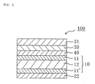
- FIG. 1 is a schematic sectional view of a liquid crystal panel according to a preferred embodiment of the present invention.
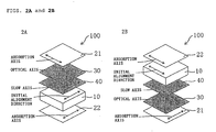
- Fig. 2A is a schematic perspective view of the liquid crystal panel employing O-mode
- Fig. 2B is a schematic perspective view of the liquid crystal panel employing E-mode. Note that, a ratio among length, width, and thickness of each member in Figs. 1 , 2A , and 2B is different from that of an actual member for clarity.
- a liquid crystal panel 100 includes a liquid crystal cell 10 having a liquid crystal layer containing liquid crystal molecules homogeneously aligned in the absence of an electric field, a first polarizer 21 arranged on one side (a viewer side in FIG.
- anysuitable protective layers can be arranged on outer sides of the first polarizer 21 and the second polarizer 22 .
- an absorption axis of the first polarizer 21 and an absorption axis of the second polarizer 22 are substantially perpendicular to each other, and an absorption axis of the first polarizer 21 and a slow axis of the second optical element 40 are substantially perpendicular to each other.
- the first optical element 30 has a substantially optically negative uniaxial property.
- the second optical element 40 exhibits a refractive index ellipsoid of nx > nz > ny, and is formed of one or more kinds of polycyclic compound having a -SO 3 M group and/or a -COOM group (M represents a counter ion).
- the third optical element 50 hassubstantiallyopticalisotropy. Bylaminatingsuchparticular optical elements respectively on a liquid crystal cell, very satisfactory optical compensation is conducted, and consequently, a liquid crystal display apparatus with a high contrast in an oblique direction of the liquid crystal display apparatus and a small color shift amount in the oblique direction can be realized.
- the second polarizer 22 is arranged so that an absorption axis thereof is substantially parallel to an initial alignment direction of the liquid crystal cell 10 .
- Thefirstpolarizer 21 is arranged so that an absorption axis thereof is substantially perpendicular to the initial alignment directionof the liquid crystal cell 10 .
- the liquid crystal panel of the present invention may be of so-called O-mode or so-called E-mode.
- liquid crystal panel of O-mode refers to a liquid crystal panel in which an absorption axis of a polarizer arranged on a backlight side of a liquid crystal cell and an initial alignment direction of the liquid crystal cell are parallel to each other.
- liquid crystal panel of E-mode refers to a liquid crystal panel in which an absorption axis of a polarizer arranged on a backlight side of a liquid crystal cell and the initial alignment direction of the liquid crystal cell are perpendicular to each other.
- the liquid crystal panel of O-mode as shown in Fig.
- the first polarizer 21 , the first optical element 30, and the second optical element 40 are preferably arranged on a viewer side of the liquid crystal cell 10
- the second polarizer 22 is preferably arranged on a backlight side of the liquid crystal cell 10.
- the first polarizer 21 , the first optical element 30 , and the second optical element 40 are preferably arranged on a backlight side of the liquid crystal cell 10
- the second polarizer 22 is preferably arranged on a viewer side of the liquid crystal cell 10 .
- an O-mode as shown in FIG. 2A is preferred. This is because more satisfactory optical compensation is realized with the O-mode arrangement.
- the second optical element including a retardation film is arranged on a farther side from the backlight, so a liquid crystal display apparatus that is unlikely to be adversely influenced by heat of the backlight and has small display unevenness can be obtained.
- the liquid crystal panel of the present invention is not limited to the above embodiment, and for example, other constituent members (for example, an optical pressure-sensitive adhesive with isotropy and an isotropic film) may be arranged between respective constituent members shown in FIG. 1 .
- other constituent members for example, an optical pressure-sensitive adhesive with isotropy and an isotropic film
- the constituent members of the liquid crystal panel of the present invention will be described in detail.
- the liquid crystal cell 10 used in the present invention is provided with a pair of substrates 11 and 11' and a liquid crystal layer 12 as a display medium interposed between the substrates 11 and 11' .
- One substrate (active matrix substrate) 11 ' is provided with as witching element (typically TFT) for controlling electrooptic properties of liquid crystals, a scanning line for providing a gate signal to the switching element and a signal line for providing a source signal thereto (all not shown).
- the other substrate (color filter substrate) 11 is provided with color filters (not shown) and black matrix (not shown). The color filters may be provided on the active matrix substrate 11' sideaswell. Adistance (cell gap) between the substrates 11 and 11' is controlled by a spacer (not shown).
- An alignment film (not shown) formed of, for example, polyimide is provided on a side of each of the substrates 11 and 11' , which is in contact with the liquid crystal layer 12 .
- the above liquid crystal layer 12 preferably includes a liquid crystal layer containing liquid crystal molecules aligned homogeneously in the absence of an electric field.
- initial alignment direction of the liquid crystal cell refers to a direction providing a maximum in-plane refractive index of the liquid crystal layer by alignment of the liquid crystal molecules in the liquid crystal layer in the absence of an electric field.
- Typical examples of drive mode using the liquid crystal layer exhibiting such refractive index profile include in-plane switching (IPS) mode, fringe field switching (FFS) mode, and ferroelectric liquid crystal (FLC) mode.
- Specific examples of liquid crystals used for those drive modes include nematic liquid crystals and smectic liquid crystals.
- the nematic liquid crystals are used for the IPS mode and the FFS mode
- the smectic liquid crystals are used for the FLC mode.
- homogeneously aligned liquid crystal molecules in the absence of an electric field respond in such an electric field as parallel to substrates generated between a counter electrode and a pixel electrode each formed of metal (also referred to as a horizontal electric field) by utilizing an electrically controlled birefringence (ECB) effect.
- EEB electrically controlled birefringence
- a normally black mode provides completely black display in the absence of an electric field by: adjusting an alignment direction of the liquid crystal cell without application of an electric field, to a direction of an absorption axis of one polarizer; and arranging polarizing plates above and below the liquid crystal cell to be perpendicular to each other. Under application of an electric field, liquid crystal molecules rotate while remaining parallel to substrates, to thereby obtain a transmittance in accordance with a rotation angle.
- the IPS mode includes super in-plane switching (S-IPS) mode and advanced super in-plane switching (AS-IPS) mode each employing a V-shaped electrode, a zigzag electrode, or the like.
- Examples of a commercially available liquid crystal display apparatus of such IPS mode include: 20V-type wide liquid crystal television “Wooo” (trade name, manufactured by Hitachi, Ltd.); 19-type liquid crystal display “ProLite E481S-1” (trade name, manufactured by Iiyama Corporation); and 17-type TFT liquid crystal display “FlexScanL565" (tradename, manufactured by Eizo Nanao Corporation).
- homogeneously aligned liquid crystal molecules in the absence of an electric field respond in such an electric field as parallel to substrates generated between a counter electrode and a pixel electrode each formed of transparent conductor (also referred to as a horizontal electric field) by utilizing an electrically controlled birefringence effect.
- the horizontal electric field in the FFS mode is also referred to as fringe electric field, which can be generated by setting a distance between the counter electrode and the pixel electrode each formed oftransparentconductornarrowerthanacellgap. Tobemorespecific, as described in " Society for Information Display (SID) 2001 Digest" (p. 484 to p.
- a normally black mode provides completely black display in the absence of an electric field by: adjusting an alignment direction of the liquid crystal cell without application of an electric field, to a direction of an absorption axis of one polarizer; and arranging polarizing plates above and below the liquid crystal cell to be perpendicular to each other. Under application of an electric field, liquid crystal molecules rotate while remaining parallel to substrates, to thereby obtain a transmittance in accordance with a rotation angle.
- A-FFS advanced fringe field switching
- U-FFS ultra fringe field switching
- An example of a commercially available liquid crystal display apparatus of such FFS mode includes Tablet PC "M1400" (trade name, manufactured by Motion Computing, Inc.).
- the above FLC mode utilizes property of ferromagnetic chiral smectic liquid crystals encapsulated between electrode substrates each having a thickness of about 1 to 2 ⁇ m to exhibit two stable states of molecular alignment, for example.
- the above ferroelectric chiral smectic liquid crystal molecules rotate within a plane parallel to the substrates and respond due to application of a voltage.
- the FLC mode can provide black and white displays based on the same principle as that of the above IPS mode or the above FFS mode. Further, the above FLC mode has such a feature in that a response speed is high compared with those in other drive modes.
- the above FLC mode includes surface stabilized ferroelectric liquid crystal (SS-FLC) mode, antiferroelectric liquid crystal (AFLC) mode, polymer stabilized ferroelectric liquid crystal (PS-FLC) mode, and V-shaped switching ferroelectric liquid crystal (V-FLC) mode.
- SS-FLC surface stabilized ferroelectric liquid crystal
- AFLC antiferroelectric liquid crystal
- PS-FLC polymer stabilized ferroelectric liquid crystal
- V-FLC V-shaped switching ferroelectric liquid crystal
- homogenous alignment includes a case where the above alignment vectors are slightly tilted with respect to the substrate plane, that is, a case where the above liquid crystal molecules are pretilted.
- a pretilt angle is preferably 20° or less for maintaining a large contrast ratio and obtaining favorable display characteristics.
- any suitable nematic liquid crystals may be employed as the above nematic liquid crystals depending on the purpose.
- the nematic liquid crystals may have positive dielectric anisotropy or negative dielectric anisotropy.
- a specific example of the nematic liquid crystals having positive dielectric anisotropy includes "ZLI-4535" (trade name, manufactured by Merck Ltd.).
- a specific example of the nematic liquid crystals having negative dielectric anisotropy includes "ZLI-2806" (trade name, manufactured by Merck Ltd.).
- a difference between an ordinary refractive index (no) and an extraordinary refractive index (ne) that is, a birefringent index ( ⁇ n LC ) of the above nematic liquid crystals can be appropriately selected in accordance with the response speed, transmittance, and the like of the above liquid crystals.
- the birefringence index is preferably 0.05 to 0.30, in general.
- smectic liquid crystals Any suitable smectic liquid crystals may be employed as the above smectic liquid crystals depending on the purpose.
- the smectic liquid crystals to be used preferably have an asymmetric carbon atom in a part of a molecular structure and exhibit ferroelectric property (also referred to as ferroelectric liquid crystals).
- smectic liquid crystals exhibiting ferroelectric property include p-decyloxybenzylidene-p'-amino-2-methylbutylcinnamate, p-hexyloxybenzylidene-p'-amino-2-chloropropylcinnamate, and 4-o-(2-methyl)butylresorcylidene-4'-octylaniline.
- ferroelectric liquid crystals examples include ZLI-5014-000(trade name, capacitance of 2.88 nF, spontaneous polarizationof -2.8 C/cm 2 , manufactured by Merck Ltd.), ZLI-5014-100 (trade name, capacitance of 3.19 nF, spontaneous polarization of -20.0 C/cm 2 , manufactured by Merck Ltd.), and FELIX-008 (trade name, capacitance of 2.26 nF, spontaneous polarization of -9.6 C/cm 2 , manufactured by Hoechst Aktiengesellschaft).
- any suitable cell gap may be employed as the cell gap (distance between substrates) of the above liquid crystal cell depending on the purpose.
- the cell gap is preferably 1.0 to 7.0 ⁇ m.
- a cell gap within the above range can reduce response time and provide favorable display characteristics.
- polarizer refers to an optical film capable of converting natural light or polarized light into any polarized light. Any suitable polarizer may be employed as a polarizer used in polarizing plate of the present invention. Preferably, a film capable of converting natural light or polarized light into linearly polarized light is used.
- the above polarizer may have any suitable thickness.
- the thickness of the polarizer is typically 5 to 80 ⁇ m, preferably 10 to 50 ⁇ m, and more preferably 20 to 40 ⁇ m.
- a thickness of the polarizer within the above ranges can provide excellent optical properties and mechanical strength.
- Atransmittance (alsoreferredtoassingleaxistransmittance) of the above polarizer measured by using a light having a wavelength of 440 nm at 23°C is preferably 41% or more, and more preferably 43% or more. Note that a theoretical upper limit of the single axis transmittance is 50%.
- a polarization degree is preferably 99.8 to 100%, and more preferably 99.9 to 100%.
- a transmittance and a polarization degree within the above ranges can further increase a contrast ratio in a front direction of a liquid crystal display apparatus employing the polarizer of the present invention.
- the above single axis transmittance and the polarization degree can be measured by using a spectrophotometer "DOT-3" (trade name, manufactured by Murakami Color Research Laboratory).
- the above polarization degree can be determined by measuring a parallel transmittance (H 0 ) and a perpendicular transmittance (H 90 ) of the polarizer and using the following equation.
- Polarization degree (%) ⁇ (H 0 -H 90 )/(H 0 +H 90 ) ⁇ 1/2 ⁇ 100.
- the above parallel transmittance (H 0 ) refers to a transmittance of a parallel laminate polarizer produced by piling two identical polarizers such that respective absorption axes of those are parallel to each other.
- the above perpendicular transmittance refers to a transmittance of a perpendicular laminate polarizer produced by piling two identical polarizers such that respective absorption axes thereof are perpendicular to each other.
- the transmittance refers to a Y value obtained through color correction by a two-degree field of view (C source) in accordance with JIS Z8701-1982.
- any suitable method may be employed as a method of arranging the first polarizer 21 and the second polarizer 22 depending on the purpose.
- the above first polarizer 21 and the second polarizer 22 are each provided with an adhesive layer or a pressure-sensitive adhesive layer (both not shown) on a surface opposing the liquid crystal cell. Then, the first polarizer 21 is bonded to a surface of the first optical element 30, and the second polarizer 22 is bonded to a surface of the third optical element 50 . In this way, contrast of a liquid crystal display apparatus employing the polarizers can be enhanced.
- a thickness of the above adhesive layer or pressure-sensitive adhesive layer may be appropriately determined in accordance with intended use, adhesive strength, and the like.
- the adhesive layer has a thickness of generally 0.1 to 50 ⁇ m, preferably 0.1 to 20 ⁇ m, and particularly preferably 0.1 to 10 ⁇ m.
- the pressure-sensitive adhesive layer has a thickness of generally 1 to 100 ⁇ m, preferably 5 to 80 ⁇ m, and particularly preferably 10 to 50 ⁇ m.
- any suitable adhesive or pressure-sensitive adhesive may be employed for forming the above adhesive layer or pressure-sensitive adhesive layer in accordance with the kind of adherend.
- an aqueous adhesive is preferably used as the adhesive.
- An adhesive containing a polyvinyl alcohol-based resin as a main component is more preferably used.
- the above first polarizer 21 is preferably arranged such that its absorption axis is substantially perpendicular to an absorption axis of the opposing second polarizer 22. With an increase in deviation from the above angle relationship of "substantially perpendicular", a contrast tends to decrease when used in a liquid crystal display apparatus.
- the above polarizer is formed of a stretched polymer film containing as a main component a polyvinyl alcohol-based resin, which contains a dichromatic substance, for example.
- the polymer film containing as a main component the above polyvinyl alcohol-based resin is produced through a method described in [Example 1] of JP 2000-315144 A , for example.
- the above polyvinyl alcohol-based resin to be used may be prepared by: polymerizing a vinyl ester-based monomer to obtain a vinyl ester-based polymer; and saponifying the resultant vinyl ester-based polymer to convert a vinyl ester unit into a vinyl alcohol unit.
- Examples of the above vinyl ester-based monomer include vinyl formate, vinyl acetate, vinyl propionate, vinyl valerate, vinyl laurate, vinyl stearate, vinyl benzoate, vinyl pivalate, and vinyl versatate. Of those, vinyl acetate is preferred.
- the above polyvinyl alcohol-based resin may have any suitable average polymerization degree.
- the average polymerization degree is preferably 1,200 to 3,600, more preferably 1,600 to 3,200, and most preferably 1,800 to 3,000. Note that the average polymerization degree of the polyvinyl alcohol-based resin can be measured through a method in accordance with JIS K6726-1994.
- a saponification degree of the above polyvinyl alcohol-based resin is preferably 90.0 to 99.9 mol%, more preferably 95.0 to 99.9 mol%, and most preferably 98.0 to 99.9 mol% from a viewpoint of durability of the polarizer.
- the above saponification degree refers to a ratio of units actually saponified into vinyl alcohol units to units which may be converted into vinyl alcohol units through saponification.
- the saponification degree of the polyvinyl alcohol-based resin may be determined in accordance with JIS K6726-1994.
- the polymer film containing as a main component a polyvinyl alcohol-based resin to be used in the present invention may preferably contain polyvalent alcohol as a plasticizer.
- the polyvalent alcohol include ethylene glycol, glycerin, propylene glycol, diethyleneglycol, triethyleneglycol, tetraethyleneglycol, and trimethylolpropane. They may be used alone or in combination.
- ethylene glycol or glycerin is preferably used from the viewpoints of stretchability, transparency, thermal stability, and the like.
- a use amount of the polyvalent alcohol in the present invention is preferably 1 to 30 (weight ratio), more preferably 3 to 25 (weight ratio) , and most preferably 0.05 to 0.3 (weight ratio) with respect to 100 of a total solid content in the polyvinyl alcohol-based resin.
- a use amount of the polyvalent alcohol within the above ranges can provide a polymer film having further improved coloring property, stretchability, and the like.
- dichromatic any suitable dichromatic substance may be employed as the above dichromatic substance.
- suitable dichromatic substance include iodine and a dichromatic dye.
- dichromatic refers to optical anisotropy in which light absorption differs in two directions of an optical axis direction and a direction perpendicular thereto.
- Examples of the above dichromatic dye include Red BR, Red LR, Red R, Pink LB, Rubin BL, Bordeaux GS, Sky Blue LG, Lemon Yellow, Blue BR, Blue 2R, Navy RY, Green LG, Violet LB, Violet B, Black H, Black B, Black GSP, Yellow 3G, Yellow R, Orange LR, Orange 3R, Scarlet GL, Scarlet KGL, Congo Red, Brilliant Violet BK, Supra Blue G, Supra Blue GL, Supra Orange GL, Direct Sky Blue, Direct First Orange S, and First Black.
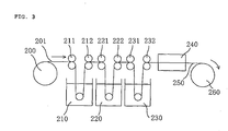
- Fig. 3 is a schematic diagram illustrating an overview of a typical production process of a polarizer used in the present invention.
- a polymer film 201 containing as a main component a polyvinyl alcohol-based resin is fed from a delivery part 200, immersed in an aqueous iodine solution bath 210, and subjected to swelling and coloring treatment under tension in a longitudinal direction of the film by rollers 211 and 212 at different speed ratios.
- the film is immersed in a bath 220 of an aqueous solution containing boric acid and potassium iodide, and subjected to cross linking treatment under tension in a longitudinal direction of the film by rollers 221 and 222 at different speed ratios.
- the film subjected to crosslinking treatment is immersed in a bath 230 of an aqueous solution containing potassium iodide by rollers 231 and 232 , and subjected to water washing treatment.
- the film subjected to water washing treatment is dried by drying means 240 to adjust its moisture content, and taken up in a winding part 260 .
- the polymer film containing as a main component the above polyvinyl alcohol-based resin may be stretched to a 5 to 7 times length of the original length through the above process to produce the polarizer 250.
- the above polarizer may have any suitable moisture content, but the moisture content is preferably 5% to 40%, more preferably 10% to 30%, and most preferably 20% to 30%.
- the polarizers may be the same or different from each other.
- the first optical element 30 is arranged between the first polarizer 21 and the second optical element 40 .
- the first optical element functions as a protective layer of the polarizer on a cell side to prevent the degradation in the polarizer. Consequently,the display characteristics of the liquid crystal display apparatus can be maintained high for a long period of time.
- the first optical element 30 has substantially optically negative uniaxial property.
- the optical element having optically negative uniaxial property ideally has an optical axis in a normal direction.
- the above first optical element is used for reducing light leakage in an oblique direction of a liquid crystal panel, in combination with the above second optical element.
- a liquid crystal panel in which two polarizers are arranged on both sides of a liquid crystal cell so that absorption axes are perpendicular to each other, light leakage is unlikely to occur in a front direction.
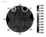
- light leakage occurs in an oblique direction, and in the case where the absorption axes of the respective polarizers are set to be 0° and 90°, the light leakage amount at an azimuth of 45° in the oblique direction tends to be maximum.
- the contrast ratio in the oblique direction can be enhanced to decrease a color shift amount in the oblique direction.
- An in-plane retardation value (Re [590]) of the first optical element used in the present invention is preferably 0 nm to 10 nm, more preferably 0 nm to 5 nm, and much more preferably 0 nm to 3 nm.
- the Rth [590] of the first optical element used in the present invention measured at a wavelength of 590 nm and 23°C, is preferably 10 nm to 100 nm, more preferably 20 nm to 80 nm, andmuchmore preferably 30 nm to 50 nm.
- any suitable method can be adopted depending on the purpose.
- adhesive layers or pressure-sensitive adhesive layers are provided on both surfaces of the above first optical element 30 , and then, the first optical element 30 is attached to the first polarizer 21 and the second optical element 40 .
- the relationship between the optical axes of the respective optical elements can be prevented from being lost and the respective optical elements can be prevented from rubbing against each other to damage them when the optical elements are incorporated in a liquid crystaldisplayapparatus.
- theinterfacereflectionbetween the layers of the respective optical elements is reduced, whereby the contrast ratio in a front direction and an oblique direction can be enhanced when they are used in a liquid crystal display apparatus.
- the thickness of the above adhesive layer or pressure-sensitive adhesive layer can be determined appropriately in a suitable range depending upon the use, the adhesive strength, and the like.
- the preferred thickness range of the adhesive is preferably 0.1 to 50 ⁇ m, more preferably 0.1 to 20 ⁇ m, and particularly preferably 0.1 to 10 ⁇ m.
- the preferred thickness range of the pressure-sensitive adhesive is preferably 1 to 100 ⁇ m, more preferably 5 to 80 ⁇ m, and particularly preferably 10 to 50 ⁇ m.
- any suitable adhesive or pressure-sensitive adhesive can be adopted.
- the adhesive include a thermoplastic adhesive, ahot-meltadhesive, a rubber-based adhesive, a thermosetting adhesive, a monomer reactive adhesive, an inorganic adhesive, and a natural adhesive.
- the pressure-sensitive adhesive include a solvent-type pressure-sensitive adhesive, a non-aqueous emulsion-type pressure-sensitive adhesive, an aqueous pressure-sensitive adhesive, a hot-melt pressure-sensitive adhesive, a liquid curable pressure-sensitive adhesive, a curable pressure-sensitive adhesive, and a pressure-sensitive adhesive by calendaring.
- the first optical element 30 in the case where nx and ny are exactly the same, a retardation value is not caused in a plane, so a slow axis is not detected, and the first optical element 30 can be arranged irrespective of the absorption axis of the first polarizer 21 and the slow axis of the second optical element 40. Even when nx and ny are substantially the same, in the case where nx and ny are slightly different from each other, a slow axis may bedetected. Inthiscase, preferably, theabovefirstopticalelement 30 is arranged so that the slow axis thereof is substantially parallel or perpendicular to the absorption axis of the first polarizer 21. As the degree at which the slow axis of the first optical element 30 is not perpendicular or parallel to the absorption axis of the first polarizer 21 increases, a contrast tends to decrease when the first optical element 30 is used in a liquid crystal display apparatus.
- the configuration (lamination structure) of the first optical element is not particularly limited, as long as the optical properties described in the above section D-1 are satisfied.
- the first optical element may be a single retardation film, or a laminate composed of two or more retardation films.
- the first optical element is a single retardation film. This is because the shift and unevenness of a retardation value caused by the shrinkage stress of a polarizer and the heat of a backlight are decreased, and the thickness of a liquid crystal panel can be reduced.
- the first optical element may include an adhesive layer and a pressure-sensitive adhesive layer.
- these retardation films may or may not be same. Note that the detail of the retardation film will be described later in the section D-4.
- the Rth [590] of the retardation film used in the first optical element can be appropriately selected depending upon the number of retardation films to be used.
- the Rth[590] of the retardation film is set to be equal to the Rth[590] of the first optical element.
- the retardation values of the pressure-sensitive adhesive layer, the adhesive layer, and the like used in laminating the above first optical element on the first polarizer and the second optical element is as small as possible.
- the total of the Rth [590] of the respective retardation films be designed to be equal to the Rth[590] of the first optical element.
- the Rth[590] of the respective retardation films can be set to be 20 nm.
- the Rth[590] of one retardation film can be set to be 10 nm, and the Rth[590] of the other retardation film can be set tobe 30 nm.
- the total thickness of the above first optical element is preferably 10 ⁇ m to 200 ⁇ m, more preferably 20 ⁇ m to 120 ⁇ m, and much more preferably 30 ⁇ m to 60 ⁇ m. Setting the above first optical element in the above thickness range can contribute to the reduction in a liquid crystal display apparatus.
- the retardation film used in the first optical element is not particularly limited, a film is preferably used which is excellent in transparency, mechanical strength, thermal stability, moisture blocking property, and the like, and in which optical unevenness is unlikely to occur due to distortion.
- the thickness of the above retardation film can be appropriately selected depending upon the purpose.
- the thickness is preferably 5 ⁇ m to 100 ⁇ m, more preferably 10 ⁇ m to 90 ⁇ m, and particularly preferably 15 ⁇ m to 60 ⁇ m. If the thickness is in the above range, a retardation film which is excellent in mechanical strength and optical uniformity and satisfies the optical properties described in the above section D-1 can be obtained.
- An absolute value (C[590] (m 2 /N)) of aphotoelastic coefficient of the above retardation film is preferably 1 ⁇ 10 -12 to 200 ⁇ 10 -12 , more preferably 1 ⁇ 10 -12 to 50 ⁇ 0 -12 , and most preferably 1 ⁇ 10 -12 to 30 ⁇ 10 -12 .
- the absolute value of the photoelastic coefficient is smaller, the shift and unevenness of a retardation value caused by the shrinkage stress of a polarizer and the heat of a backlight are unlikely to occur when the retardation film is used in a liquid crystal display apparatus, and a liquid crystal display apparatus excellent in display uniformity can be obtained.
- the transmittance of the above retardation film measured with light having a wavelength of 590 nm at 23°C, is preferably 80% or more, more preferably 85% or more, and particularly preferably 90% or more. It is preferred that the first optical element also have the similar light transmittance.
- the above retardation film is preferably a polymer film containing a thermoplastic resin as a main component.
- the above thermoplastic resin may be an amorphous polymer or a crystalline polymer.
- the amorphous polymer has an advantage of being excellent in transparency, and the crystalline polymer has an advantage of being excellent in stiffness, strength, and drug resistance.
- the polymer film containing the above thermoplastic resin as a main component may or may not be stretched.
- thermoplastic resin examples include: general purpose plastics such as polyethylene, polypropylene, polynorbornene, polyvinyl chloride, a cellulose ester, polystyrene, an ABS resin, an AS resin, polymethyl methacrylate, polyvinyl acetate, and polyvinylidene chloride; general purpose engineering plastics such as polyamide, polyacetal, polycarbonate, modified polyphenylene ether, polybutylene terephthalate, and polyethylene terephthalate; and super engineering plastics such as polyphenylene sulfide, polysulfone, polyethersulfone, polyetheretherketone, polyarylate, a liquid crystalline polymer, polyamideimide, polyimide, and polytetrafluoroethylene.
- general purpose plastics such as polyethylene, polypropylene, polynorbornene, polyvinyl chloride, a cellulose ester, polystyrene, an ABS resin, an AS resin, polymethyl methacrylate, polyvin
- thermoplastic resin may be used alone or in combination. Further, the above thermoplastic resin may be used after any suitable polymer modification. Examples of the polymer modification include copolymerization, crosslinking, and modifications in molecular terminals and stereoregularity.
- a retardation film used in the first optical element is particularly preferably a polymer film containing as a main component a cellulose ester.
- Any suitable cellulose ester may be employed as the above cellulose ester.
- Specific examples thereof include organic acid esters such as cellulose acetate, cellulose propionate, and cellulose butyrate.
- the above cellulose ester may be a mixed organic acid ester in which hydroxy groups of cellulose are partly substituted with an acetyl group and a propionyl group, for example.
- the above cellulose ester is produced, for example, through a method described in paragraphs [0040] and [0041] of JP 2001-188128 A .
- the above cellulose ester has a weight average molecular weight (Mw) of preferably 20,000 to 300,000, and more preferably 50,000 to 250,000, and particularly preferably 70,000 to 200,000.
- Mw weight average molecular weight
- a weight average molecular weight of the cellulose ester within the above ranges can provide a transparent film having excellent thermal stability and mechanical strength.
- Any suitable forming processing may be employed as a method of obtaining the polymer film containing as a main component the above thermoplastic resin.
- Any suitable method may be selected from compressionmolding, transfermolding, injectionmolding, extrusion molding, blow molding, powder molding, FRP molding, casting method, and the like. Of those, casting method is preferred because a highly smooth retardation film with small Re[590] and favorable optical uniformity (for example, uniformity of retardation value in plane and in the thickness direction) can be obtained.
- the above casting method involves: defoaming a rich solution (dope) prepared by dissolving in a solvent a resin composition containing a thermoplastic resin as main component, a plasticizer, an additive, and the like; uniformly casting the defoamed solution into a sheet on a surface of an endless stainless steel belt or rotating drum; and evaporating the solvent to produce a film.
- the conditions to be employed in formation of the polymer film containing as a main component the above thermoplastic resin may appropriately be selected in accordance with the composition or kind of the resin, a forming processing, and the like.
- a solvent to be used include cyclopentanone, cyclohexanone, methyl isobutyl ketone, toluene, ethyl acetate, dichloromethane, chloroform, and tetrahydrofuran.
- a retardation film having highly optical uniformity can be obtained.
- a temperature range for drying of the above solvent is preferably 50°C to 250°C, and more preferably 80°C to 150°C. A temperature within the above ranges can provide a retardation film having small Re [590] and highly optical uniformity.
- Rth[590] may appropriately be adjusted in accordance with drying conditions, a thickness of the film after formation, and the like.
- the polymer film containing as a main component the above thermoplastic resin may further contain any suitable additive.
- the additive include a plasticizer, a thermal stabilizer, a light stabilizer, a lubricant, an antioxidant, a UV absorber, a flame retardant, a colorant, an antistatic agent, a compatibilizing agent, a crosslinking agent, and a thickener.
- the kind and amount of the additive to be used may be appropriately set in accordance with the purpose.
- a content of the additive is preferably 10 (weight ratio) or less, more preferably 5 (weight ratio) or less, and most preferably 3 (weight ratio) or less with respect to 100 of a total solid content in the polymer film.
- a retardation film used in the above first optical element is a stretched film.
- the retardation film used in the above first optical element may be formed of a stretched film of the polymer film containing as a main component a thermoplastic resin.
- the term "stretched film” refers to a plastic film having enhanced alignment of molecules in a specific direction obtained by: applying tension to an unstretched film at an appropriate temperature; or applying tension to a film stretched in advance.
- Any suitable stretching method may be employed as a method of forming the above stretched film.
- Specific examples of the stretching method include a vertical uniaxial stretching method, a transverse uniaxial stretching method, a vertical and transverse simultaneous biaxial stretching method, and a vertical and transverse sequential biaxial stretching method.
- Any suitable stretching machine suchas a roll stretchingmachine, atenterstretchingmachine, or a biaxial stretching machine may be used as stretching means.
- a stretching temperature may be continuously changed or may be changed in steps. Further, the stretching may be performed in two or more steps.
- a commercially available optical film may be directly used as the polymer film containingasamaincomponenttheabovethermoplasticresin. Further, a commercially available optical film may be subj ected to fabrication such as stretching treatment and/or relaxation treatment before use.
- Specific examples of a commercially available polymer film containing a cellulose ester as a main component include "FUJITAC series" (TD, UZ, etc., trade name, available from Fuji Photo Film Co., Ltd.).
- the second optical element 40 is arranged between the first optical element 30 and the liquid crystal cell 10.
- the above second optical element is used for reducing light leakage in an oblique direction of a liquid crystal panel, in combination with the above first optical element.
- a liquid crystal panel in which two polarizers are arranged on both sides of a liquid crystal cell so that absorption axes are perpendicular to each other, light leakage is unlikely to occur in a front direction.
- light leakage occurs in an oblique direction, and in the case where the absorption axes of the respective polarizers are set to be 0° and 90°, the light leakage amount at an azimuth of 45° in the oblique direction tends to be maximum.
- the contrast ratio in the oblique direction can be enhanced to decrease a color shift amount in the oblique direction.
- the second optical element used in the present invention exhibits a refractive index ellipsoid of nx > nz > ny.
- the in-plane retardation Re [590] of the second optical element used in the present invention at a wavelength of 590 nm and 23°C is preferably 100 nm to 300 nm, more preferably 130 nm to 270 nm, and much more preferably 160 nm to 230 nm. In these ranges, a suitable value can be selected appropriately depending upon the value of Rth[590] of the first optical element described above.
- the sum of the Rth[590] of the first optical element and the Rth[590] of the second optical element is preferably [( ⁇ /2) - 100] nm to [( ⁇ /2) + 100] nm, more preferably [( ⁇ /2) - 80] nm to [( ⁇ /2) + 80] nm, and much more preferably [( ⁇ /2) - 50] nm to [( ⁇ /2) + 50] nm.
- the sum of the Rth[590] of the first optical element and the Re[590] of the second optical element is closer to ( ⁇ /2) nm, light leakage can be decreased.
- the retardation value of the optical element may change depending upon the wavelength. This is referred to as the wavelength dispersion properties of the optical element (or the retardation film).
- the above wavelength dispersion properties can be obtained by a ratio: Re[480]/Re[590] of retardation values in a plane measured with light having wavelengths of 480 nm and 590 nm at 23°C.
- Re[480]/Re[590] of the second optical element used in the present invention is preferably 0.8 to 1.2, more preferably 0.8 to 1.1, and particularly preferably 0.8 to 1.05.
- the retardation value becomes constant in a wider region of visible light. Therefore, in the case of using the second optical element in a liquid crystal display apparatus, the deviation of a wavelength is unlikely to occur in leaking light, and the color shift amount in an oblique direction of the liquid crystal display apparatus can be further decreased.
- the Rth [590] of the second optical element used in the present invention is preferably 30 nm to 130 nm, and more preferably 40 nm to 120 nm in a range satisfying 0 ⁇ Rth [590] ⁇ Re [590].
- the above Rth can be selected appropriately considering the ratio (which is also referred to as anNz coefficient) between the thickness direction retardation value (Rth[590]) and the in-plane retardation value (Re[590]) described later.
- the Rth[590]/Re[590] refers to a ratio (which is also referred to as anNz coefficient) between the thickness direction retardation value Rth[590] and the in-plane retardation value Re[590] measured with light having a wavelength of 590 nm at 23°C.
- the Nz coefficient of the above second optical element is preferably 0.05 to 0.45, more preferably 0.1 to 0.4, much more preferably 0.2 to 0.4, and particularly preferably 0.25 to 0.35.
- any suitable method can be adopted depending upon the purpose.
- a lyotropic liquid crystal aqueous solution forming the second optical element is applied to the surface of the first optical element (more preferably, the first optical element whose surface is subjected to saponification treatment), whereby the second optical element is formed on the first optical element.
- the second optical element by coating, a second optical element with a very small thickness can be obtained.
- the above second optical element 40 is arranged so that a slow axis thereof is substantially perpendicular to an absorption axis of the first polarizer 21 .
- the contrast tends to decrease when the second optical element 40 is used in a liquid crystal display apparatus.
- the configuration (lamination structure) of the second optical element is not particularly limited as long as the optical properties described in the above section E-1 are satisfied.
- the second optical element may be a single layer or a plurality of layers. The detail of a material and the like for forming the second optical element will be described later in the section E-4.
- the total thickness of the above second optical element is preferably 0.05 to 10 ⁇ m, more preferably 0.1 to 5 ⁇ m, and much more preferably 0.2 to 3 ⁇ m.
- the second optical element in the present invention is obtained as a layer (coating layer) formed by coating, so the second optical element can have a very small thickness as described above. This can contribute to the thinning of the liquid crystal display apparatus.
- the second optical element is formed of one or more kinds of polycylic compound having a -SO 3 M group and/or a-COOM group (M represents a counter ion).
- the -SO 3 M group represents a sulfonic acid group or a sulfonate group.
- the -COOM group represents a carboxylic acid group or a carboxylate group.
- examples of the M include a hydrogen atom, an alkali metal atom, an alkaline-earth metal atom, a metal ion, or a substituted or unsubstituted ammonium ion.
- examples of the above metal ion include Ni 2+ , Fe 3+ , Cu 2+ , Ag + , Zn 2+ , Al 3+ , Pd 2+ , Cd 2+ , Sn 2+ , Co 2+ , Mn 2+ , and Ce 3+ .
- the above polycyclic compound preferably exhibits a liquid crystal phase in a solution state (i.e., lyotropic liquid crystal).
- the above liquid crystal phase is preferably a nematic liquid crystal phase in terms of the excellent alignment property.
- the above polycyclic compound is preferably an organic compound having two or more aromatic rings and/or heterocycles in a molecular structure, more preferably an organic compound having 3 to 8 aromatic rings and/or heterocycles in a molecular structure, and much more preferably an organic compound having 4 to 6 aromatic rings and/or heterocycles in a molecular structure.
- the above polycylic compound necessarily contains heterocycles in a molecular structure.
- any suitable heteroatom can be selected.
- the heteroatom is preferably a nitrogen atom.
- the above polycyclic compound is preferably a compound represented by General Formula (1).
- M represents a counter ion
- k and 1 respectively represent integers of 0 to 4 independently
- the sum of k and 1 is an integer of 0 to 4
- m and n respectively represent integers of 0 to 6 independently
- the sum of m and n is an integer of 0 to 6
- k, 1, m and n do not represent 0 at the same time.
- a lyotropic liquid crystal aqueous solution containing both acenaphtho[1,2-b]quinoxaline-2-sulfonic acid, and acenaphtho [1,2-b] quinoxaline-2,5-disulfonic acid is applied to the surface of the first optical element (more preferably, the first optical element whose surface is subjected to saponification treatment) to form the second optical element.
- Acenaphtho[1,2-b]quinoxaline derivative represented by General Formula (1) can be obtained by sulfonating an acenaphtho[1,2-b]quinoxaline compound with sulfuric acid, fuming sulfuric acid, or chlorosulfonic acid, as represented by General Formula (2).
- the acenaphtho[1,2-b]quinoxaline derivative represented by General Formula (1) can also be obtained by the condensation reaction between a benzene-1,2-diamine compound and an acenaphthoquinone compound, as represented by General Formula (3).
- General Formula (3) Mrepresentsacounterion, kandlrespectively represent integers of 0 to 4 independently, the sum of k and 1 is an integer of 0 to 4, m and n respectively represent integers of 0 to 6 independently, the sum of m and n is an integer of 0 to 6, and k, 1, m and n do not represent 0 at the same time.
- the second optical element of the present invention can be formed by any suitable method.
- the second optical element is produced by a method including the following steps (1) to (3) .
- the above solution is prepared, preferably, by dissolving two or more kinds of polycylic compounds having different substitution positions of a -SO 3 M group and/or a -COOM group in a solvent.
- the number of kinds of the polycyclic compounds contained in the above solution is preferably 2 or more, more preferably 2 to 6, and particularly preferably 2 to 4, excluding a trance amount of compounds contained as impurities.
- the above solvent is used for dissolving the above polycyclic compounds to allow a nematic liquid crystal phase to be expressed.
- any suitable one can be selected.
- the above solvent may be, for example, an inorganic solvent such as water, or an organic solvent such as alcohols, ketones, ethers, esters, aliphatic and aromatic hydrocarbons, halogenated hydrocarbons, amides, and cellosolves.
- Examples of the above solvent include: n-butanol, 2-butanol, cyclohexanol, isopropyl alcohol, t-butyl alcohol, glycerine, ethylene glycol, acetone, methyl ethyl ketone, methyl isobutyl ketone, cyclohexanone, cyclopentanone, 2-pentanone, 2-hexanone, diethyl ether, tetrahydrofuran, dioxane, anisole, ethyl acetate, butyl acetate, methyl lactate, n-hexane, benzene, toluene, xylene, chloroform, dichloromethane, dichloroethane, dimethylformamide, dimethylacetamide, methyl cellosolve, ethyl cellosolve. These solvents may be used alone or as a mixture.
- the above solvent is preferably water.
- the electrical conductivity of the above water is preferably 20 ⁇ S/cm or less, more preferably 0.001 ⁇ S/cm to 10 ⁇ S/cm, and particularly preferably 0.01 ⁇ S/cm to 5 ⁇ S/cm.
- the lower limit value of the electrical conductivity of the above water is 0 ⁇ S/cm.
- the concentration of a polycyclic compound in the above solution can be appropriately prepared in a range exhibiting a nematic liquid crystal phase, depending upon the kind of a polycyclic compound to be used.
- the concentration of the polycyclic compound in the above solution is preferably 5% by weight to 40% by weight, more preferably 5% by weight to 35% by weight, and much more preferably 5% by weight to 30% by weight.
- the concentration of the solution in the above range the solution can form a stable liquid crystal state.
- the above nematic liquid crystal phase can be checked and identified based on the optical pattern of a liquid crystal phase observed with a polarization microscope.
- the above solution can further contain any suitable additive.
- suitable additive include a surfactant, a plasticizer, a thermal stabilizer, a light stabilizer, a lubricant, an antioxidant, a UV-absorber, a fire retardant, a colorant, an antistatic agent, a compatibilizing agent, a cross-linking agent, and a thickener.
- the adding amount of the above additive is preferably more than 0 and 10 or less parts by weight with respect to 100 parts by weight of the solution.
- the above solution can further contain a surfactant.
- the surfactant is used for enhancing the wettability and application property of a polycylic compound with respect to the surface of a base material.
- the above surfactant is preferably a nonionic surfactant.
- the adding amount of the above surfactant is preferably more than 0 and 5 or less parts by weight with respect to 100 parts by weight of the solution.
- hydrophilization treatment in the above step (2) refers to the treatment of decreasing the contact angle of water with respect to a base material.
- the above hydrophilization treatment is used for enhancing the wettability and application property of the surface of a base material to which a polycyclic compound is to be applied.
- the above hydrophilization treatment is the treatment of decreasing the contact angle of water at 23°C with respect to a base material by preferably 10% or more, more preferably 15% to 80%, and much more preferably 20% to 70%, compared with that before the treatment.
- the decrease ratio (%) is obtained by an expression: ⁇ (Contact angle before treatment - Contact angle after treatment)/Contact angle before treatment ⁇ ⁇ 100.
- the above hydrophilization treatment is the treatment of decreasing the contact angle of water at 23°C with respect to a base material by preferably 5° or more, more preferably 10° to 65°, and much more preferably 20° to 65°, compared with that before the treatment.
- the above hydrophilization treatment is the treatment of setting the contact angle of water at 23°C with respect to a base material to preferably 5° to 60°, more preferably 5° to 50°, and much more preferably 5° to 45°.
- the above hydrophilization treatment may be, for example,adrytreatmentorwettreatment.
- thedrytreatment include: a discharge treatment such as a corona treatment, a plasma treatment, and a glow discharge treatment; and an ionization actinic rays treatment such as a frame treatment, an ozone treatment, a UV-ozone treatment, aUV-treatment, andanelectronic line treatment.
- the wet treatment include an ultrasonic treatment using a solvent such as water or acetone, an alkali treatment, and an anchor coat treatment. These treatments may be used alone or in combination.
- the above hydrophilization treatment is a corona treatment, a plasma treatment, an alkali treatment, or an anchor coat treatment.
- a second optical element having high alignment property and small variation in thickness can be obtained.
- the conditions of the above hydrophilization treatment such as a treatment time and intensity, can be appropriately and suitably adjusted so that the contact angle of water with respect to a base material is in the above range.
- the above corona treatment is typically a treatment of reforming the surface of a base material by allowing the base material to pass through a corona discharge generated by applying a high frequency and high voltage between a grounded dielectric roll and an insulated electrode to subject air therebetween to dielectric breakdown so that a irisionized.
- the above plasma treatment is typically a treatment of reforming the surface of a base material by allowing the base material to pass through a low-temperature plasma generated when a glow discharge occurs in inorganic gas such as low-pressure inactive gas, oxygen, or halogen gas, and a part of gas molecules are ionized.
- the above ultrasonic cleaning treatment is typically a treatment of improving the wett ability of a base material by removing a contaminant on the surface of a base material by immersing the base material in water or an organic solvent and applying an ultrasonic wave to the base material.
- the above alkali treatment is typically a treatment of reforming the surface of a base material by immersing the base material in an alkali treatment solution in which a basic material is dissolved in water or an organic solvent.
- the above anchor coat treatment is typically a treatment of applying an anchor coat agent to the surface of a base material.
- the base material used in the present invention is used for uniformly flow-casting a solution containing the above polycylic compound and solvent.
- the above base material any suitable one can be selected.
- the first optical element preferably can correspond to the above base material.
- the application speed of the solution in the above step (3) is preferably 50 mm/second or more, and more preferably 100 mm/second or more.
- a shear force suitable for aligning a polycyclic compound is applied to the solution used in the present invention, and a second optical element having a high in-plane birefringent index and a small variation in thickness can be obtained.
- any suitable application method employing a coater may be adopted.
- the above coater include a bar coater, a reverse roll coater, a positive rotation roll coater, a gravure coater, a knife coater, a rod coater, a slot die coater, a slot orifice coater, a curtain coater, a fountain coater, an air doctor coater, a kiss coater, a dip coater, a bead coater, a blade coater, a cast coater, a spray coater, a spin coater, an extrusion coater, and a hot melt coater.
- preferred examples of the coater used in the present invention include a bar coater, a reverse roll coater, a positive rotation roll coater, a gravure coater, a rod coater, a slot die coater, a slot orifice coater, a curtain coater, and a fountain coater.
- An application method employing the above coater can provide a very thin second optical element having a small variation in thickness.
- drying means such as an air-circulating thermostatic oven in which hot air or cool air circulates; a heater using microwaves, far infrared rays, or the like; a heated roller for temperature adjustment; a heat pipe roller; and a heated metal belt.
- the temperature for drying the above solution be an isotropic phase transition temperature or lower of the above solution, and the solution is dried by raising the temperature from a low temperature to a high temperature gradually.
- the above drying temperature is preferably 10°C to 80°C, and more preferably 20°C to 60°C. If the drying temperature is in the above temperature range, a second optical element having a small variation in thickness can be obtained.
- the time for drying the above solution may be appropriately selected depending upon the drying temperature and the kind of a solvent.
- the time for drying the above solution is preferably 1 minute to 30 minutes, and more preferably 1 mitute to 10 minutes.
- the second optical element of the present invention may be produced by further performing the following step (4) after the above steps (1) to (3).
- (4) The step of bringing a solution containing at least one kindof compound salt selected from the group consisting of an aluminum salt, a barium salt, a lead salt, a chromium salt, a strontium salt, and a compound salt having two or more amino groups in molecules into contact with the film obtained in the above step (3).
- the above step (4) is used for insolubilizing the second optical element or rendering it hardly soluble with respect to water.
- the above compound salt include aluminum chloride, barium chloride, lead chloride, chromium chloride, strontium chloride, 4,4'-tetramethyldiaminodiphenylmethane hydrochloride, 2,2'-dipyridyl hydrochloride, 4,4'-dipyridyl hydrochloride, melamine hydrochloride, and tetraaminopyrimidine hydrochloride.
- the compound salt concentration of a solution containing the above compound salt is preferably 3% by weight to 40% by weight, and more preferably 5% by weight to 30% by weight.
- any method can be adopted, such as a method of applying a solution containing the above compound salt to the surface of the second optical element and a method of immersing the second optical element in a solution containing the above compound salt.
- the obtained second optical element be washed with water or any solvent, and the resultant optical element is further dried, whereby a laminate excellent in adhesiveness of the interface between the base material and the second optical element can be obtained.
- a third optical element having substantially optical isotropy maybe arranged between the second polarizer and the liquid crystal cell.
- the third optical element functions as a protective layer of the polarizer on the cell side, which prevents the degradation of the polarizer, and consequently, the display characteristics of the liquid crystal display apparatus can be kept high for a long period of time.
- the present specification includes not only the case where nx, ny, and nz are each exactly the same, but also the case where they are substantially the same (nx ⁇ ny ⁇ nz).
- the phrase "the case where nx, ny, and nz are substantially the same” includes, for example, the case where an in-plane retardation value (Re [590]) is 10 nm or less and an absolute value of a thickness direction retardation value (Rth[590]) is 10 nm or less.
- the third optical element is used for eliminating the adverse influence exerted on the display characteristics of the liquid crystal display apparatus.
- a liquid crystal layer(consequently, a liquid crystal cell) containing liquid crystal molecules aligned homogeneously has a retardation comparable to the product of a cell gap and a birefringent index of a liquid crystal layer.
- the retardation of the liquid crystal layer may synergistically function with the retardation of the third optical element to adversely influence the display characteristics of the liquid crystal display apparatus greatly.
- the absolute value of the thickness direction retardation value of the above third optical element exceeds 10 nm, the light leakage of the liquid crystal display apparatus occurs, the contrast ratio in an oblique direction decreases, and the color shift amount in the oblique direction tends to increase.
- the adverse influence exerted on the display characteristics of the liquid crystal display apparatus by the retardation of the above liquid crystal layer can be eliminated. Consequently, the optical compensation obtained by the combination of the first optical element and the second optical element is exhibited sufficiently, and a liquid crystal display apparatus having satisfactory display characteristics can be obtained.
- the Re[590] of the third optical element that can be used in the present invention is preferably as small as possible.
- the Re [590] is preferably 5 nm or less, and more preferably 3 nm or less. If the Re [590] is in the above range, the contrast ratio in the oblique direction of the liquid crystal display apparatus is enhanced, and the color shift amount in the oblique direction can be decreased.
- the Rth [590] of the above third optical element is also preferably as small as possible.
- the absolute value of the Rth [590] is preferably 7 nm or less and more preferably 5 nm or less.
- any suitable method can be adopted depending upon the purpose.
- adhesive layers orpressure-sensitive adhesive layers are provided on both sides of the above third optical element, and the third optical element is attached to the liquid crystal cell and the second polarizer.
- the relationship between the optical axes of the respective optical elements can be prevented from being lost and the respective optical elements can be prevented from rubbing against each other to damage them when the optical elements are incorporated in a liquid crystal display apparatus.
- the interface reflection between the layers of the respective optical elements is reduced, whereby the contrast ratio in a front direction and an oblique direction can be enhanced when they are used in a liquid crystal display apparatus.
- the thickness of the above adhesive layer or pressure-sensitive adhesive layer and the kind of the adhesive or pressure-sensitive adhesive forming the adhesive layer or pressure-sensitive adhesive layer, those which are in the same range as those described in the above section D-2 can be adopted.
- the third optical element in the case where nx and ny are exactly the same, a retardation value is not caused in a plane, so a slow axis is not detected, and the third optical element can be arranged irrespective of the absorption axis of the second polarizer. Even when nx and ny are substantially the same, in the case where nx and ny are slightly different from each other, a slow axis may be detected.
- the above third optical element is arranged so that the slow axis thereof is substantially parallel or perpendicular to the absorption axis of the second polarizer. As the degree at which the slow axis of the third optical element is not perpendicular or parallel to the absorption axis of the second polarizer increases, a contrast tends to decrease when the third optical element is used in a liquid crystal display apparatus.
- the configuration (lamination structure) of the third optical element is not particularly limited, as long as the optical properties described in the above section F-1 are satisfied.
- the above third optical element may be a single optical film, or a laminate composed of two or more optical films.
- the third optical element may include an adhesive layer or a pressure-sensitive adhesive layer for attaching the above optical film.
- the above optical film may be an isotropic film or a retardation film.
- the respective retardation films are preferably arranged so that slow axes thereof are perpendicular to each other. Due to such arrangement, an in-plane retardation value can be decreased.
- the total thickness of the above third optical element is preferably 20 ⁇ m to 500 ⁇ m, more preferably 20 ⁇ m to 400 ⁇ m, and much more preferably 20 ⁇ m to 200 ⁇ m. Setting the total thickness in the above range can contribute to the reduction in thickness of the liquid crystal display apparatus.
- An optical film used in a third optical element is preferably an isotropic film.
- the term "isotropic film” refers to a film having a small optical difference in a three-dimensional direction, and exhibiting substantially no an isotropic optical properties such as birefringence. Note that the phrase "exhibiting substantially no an isotropic optical properties" refers to that the case where the display characteristics of the liquid crystal display apparatus is not adversely influenced practically even though birefringence occurs slightly is included in the isotropic case.
- the isotropic film used in the third optical element is not particularly limited, and a film is preferably used which is excellent in transparency, mechanical strength, thermal stability, moisture blocking property, and the like, and in which optical unevenness is unlikely to be caused by distortion.
- the thickness of the above isotropic film can be appropriately selected depending upon the purpose and the lamination structure of the third optical element.
- the thickness of the above isotropic film is preferably 20 ⁇ m to 200 ⁇ m, more preferably 20 ⁇ m to 180 ⁇ m, and much more preferably 20 ⁇ m to 150 ⁇ m. If the thickness of the above isotropic film is in the above range, an optical film being excellent in mechanical strength and optical uniformity and satisfying the optical properties described in the above section F-1 can be obtained.
- the absolute value (C[590](m 2 /N)) of the photoelastic coefficient of the above isotropic film is preferably 1 ⁇ 10 -12 to 100 ⁇ 10 -12 , more preferably 1 ⁇ 10 -12 to 50 ⁇ 10 -12 , much more preferably 1 ⁇ 10 -12 to 30 ⁇ 10 -12 , and particularly preferably 1 ⁇ 10 -12 to 8 ⁇ 10 -12 .
- the absolute value of the photoelastic coefficient is smaller, when the isotropic film is used in a liquid crystal display apparatus, the displacement and unevenness of retardation values caused by the shrinkage stress of a polarizer and the heat of a backlight are unlikely to occur, whereby a liquid crystal display apparatus excellent in display uniformity can be obtained.
- the transmittance of the above isotropic film measured with light having a wavelength of 590 nm at 23°C is preferably 80% or more, more preferably 85% or more, and much more preferably 90% or more. It is preferred that the third optical element have a light transmittance similar to the above.
- the above isotropic film is preferably a stretched film of a polymer film containing a thermoplastic resin as a main component.
- a thermoplastic polymer for example, any suitable polymer such as those described in the above section D-4 can be selected.
- the isotropic film used in the third optical element is more preferably a polymer film containing, as a main component, at least one resin selected from a cellulose ester, a cycloolefin-based resin obtained by hydrogenating a ring-opening polymer of a norbornene-based monomer, an addition copolymer of a norbornene-based monomer and an ⁇ -olefin monomer, and an addition copolymer of a maleimide-based monomer and an olefin monomer.
- any suitable cellulose ester can be adopted. Specific examples there of include organic acid esters such as cellulose acetate, cellulose propionate, and cellulose butyrate. Further, the above cellulose ester may be a mixed organic acid ester in which hydroxy groups of cellulose are partly substituted with an acetyl group and a propionyl group, for example.
- the film can be obtained by, for example, the method described in Example 1 of JP 7-112446 A . Further, the film can also be obtained with the Rth [590] before treatment decreased by swelling a commercially available film with a ketone-based solvent such as cyclopentanone, followed by drying.
- a ketone-based solvent such as cyclopentanone
- any suitable resin can be adopted.
- a polymer film containing, as a main component, the cycloolefin-based resin obtained by hydrogenating a ring-opening polymer of a norbornene-based monomer include "ZEONEX series" (480, 480R, etc.) (trade name) manufactured by Nippon Zeon Co., Ltd., "Zeonor series” (ZF14, ZF16, etc.) (trade name) manufactured by Nippon Zeon Co., Ltd.
- the film can be obtained by, for example, the method described in Example 1 of JP 4-301415 A .
- the above addition copolymer of a norbornene-based monomer and ⁇ -olefin monomer can be obtained by, for example, the method described in Example 1 of JP 61-292601 A .
- the liquid crystal panel of the present invention may be used for: a liquid crystal display apparatus such as a personal computer, a liquid crystal television, a cellular phone, or a personal digital assistance (PDA) ; or an image display apparatus such as an organic electroluminescence display (organic EL), a projector, a projection television, oraplasmatelevision.
- a liquid crystal display apparatus such as a personal computer, a liquid crystal television, a cellular phone, or a personal digital assistance (PDA)
- PDA personal digital assistance
- an image display apparatus such as an organic electroluminescence display (organic EL), a projector, a projection television, oraplasmatelevision.
- Inparticular,theliquidcrystal panel of the present invention is preferably used for a liquid crystal display apparatus, and particularly preferably used for a liquid crystal television.
- FIG. 4 is a schematic sectional view of a liquid crystal display apparatus according to a preferred embodiment of the present invention.
- a liquid crystal display apparatus 400 is provided with: a liquid crystal panel 100 of the present invention; protective layers 60 and 60' arranged on both sides of the liquid crystal panel 100; surface treated layers 70 and 70' arranged on outer sides of the protective layers 60 and 60'; a brightness enhancement film 80, a prism sheet 110, a light guide plate 120, and a lamp 130 arranged on an outer side (backlight side) of the surface treated layer 70'.
- Treated layers subjected to hard coat treatment, antireflection treatment, anti-sticking treatment, diffusion treatment (also referred to as anti-glare treatment), or the like are used as the above surface treated layers 70 and 70'.
- a polarization separation film having a polarization selection layer "D-BEF series" (trade name, available from Sumitomo 3M Limited, for example) or the like is used as the above brightness enhancement film 80.
- D-BEF series polarization selection layer
- Those optical members are used, to thereby obtain a display apparatus with better display characteristics.
- the optical members shown in Fig. 4 may be partly omitted or replaced by other members in accordance with the drive mode or application of the liquid crystal cell to be used as long as the effects of the present invention are obtained.
- the intended use of the liquid crystal panel and liquid crystal display apparatus of the present invention is not particularly limited, but the liquid crystal panel and the liquid crystal display apparatus of the present invention may be used for various purposes such as: office automation (OA) devices such as a personal computer monitor, a laptop personal computer, and a copying machine; portable devices such as a cellular phone, a watch, a digital camera, a personal digital assistance (PDA), and a portable game machine; domestic electric appliances such as a video camera, a liquid crystal television, andamicrowave; in-cardevicessuchasabackmonitor, acarnavigation system monitor, and a car audio; display devices such as a commercial information monitor; security devices such as a surveillance monitor; and nursing care/medical devices such as a nursing monitor and a medical monitor.
- OA office automation
- portable devices such as a cellular phone, a watch, a digital camera, a personal digital assistance (PDA), and a portable game machine
- domestic electric appliances such as a video camera, a liquid
- a polymer film "9P75R" (trade name, thickness: 75 ⁇ m, average polymerization degree: 2,400, saponification degree: 99.9 mol%, manufactured by Kuraray Co., Ltd.) containing polyvinyl alcohol as a main component was uniaxially stretched 2.5 times by using a roll stretching machine while the polymer film was colored in a coloring bath maintained at 30°C ⁇ 3°C and containing iodine and potassium iodide.
- the polymer film was uniaxially stretched to a 6 times length of the original length of the polyvinyl alcohol film in an aqueous solution maintained at 60°C ⁇ 3°C and containing boric acid and potassium iodide while a cross-linking reaction was performed.
- the obtained film was dried in an air circulating thermostatic oven at 50°C ⁇ 1°C for 30 minutes, to thereby obtain polarizers P1 and P2 with a moisture content of 26%, a thickness of 28 ⁇ m, a polarization degree of 99.9%, and a single axis transmittance of 43.5%.
- a triacetyl cellulose film "FUJITACUZ" (trade name, thickness: 80 ⁇ m, manufactured by Fuji Photo Film Co., Ltd.) was used as a polarizer protective film.
- a triacetylcellulose film "ZRF80S" (trade name, thickness: 80 ⁇ m, manufactured by Fuji Photo Film Co., Ltd.) was immersed in an aqueous solution in which sodium hydroxide was dissolved, and the surface of the film was subjected to an alkali treatment (saponification treatment) .
- the contact angle of water at 23°C with respect to the film after the alkali treatment was 42.2° (64.6° before the treatment).
- the o-phenylenediamine solution was gradually added to the acenaphthenequinone solution over 1 hour while stirring under a nitrogen atmosphere, and thereafter, they were allowed to react with each other by further continuing stirring for 3 hours.
- Ion exchange water was added to the obtained reaction solution, and a precipitate was filtered to obtain a crude product.
- the crude product was recrystallized with heated glacial acetic acid to obtain purified QAN.
- 2-sulfo-QAN obtained in Reference Example 5 and 2,5-sulfo-QAN obtained in Reference Example 6 were dissolved in 30 L of ion exchange water (electric conductivity: 0.1 ⁇ S/cm), and a sodium hydroxide aqueous solution was added to the solution to neutralize it.
- the obtained aqueous solution was arranged in a supply tank and circulation-filtered while reverse osmosis water was being added so as to obtain a constant liquid amount, using a high-pressure RO element test apparatus equipped with a reverse osmosis membrane filter "NTR-7430 filter element" (trade name, manufactured by Nitto Denko Corporation), and remaining sulfuric acid was removed until the electric conductivity of waste liquid reached 10 ⁇ S/cm.
- NTR-7430 filter element trade name, manufactured by Nitto Denko Corporation
- this aqueous solution was adjusted so that the concentration of a polycylic compound in an aqueous solution became 23% by weight, using a rotary evaporator.
- the aqueous solution thus obtained was observed with a polarizationmicroscope, it exhibited a lyotropic liquid crystal phase at 23°C.
- the composition ratio between the sodium salt of 2-sulfo-QAN and the sodium salt of 2, 5-sulfo-QAN in the aqueous solution was quantified by liquid chromatographic analysis, the composition ratio of the sodium salt of 2-sulfo-QAN and the sodium salt of 2,5-sulfo-QAN was 45 : 55.
- the reaction path is shown in Formulae (6) and (7).
- a commercially available polymer film "ZRF80S” (trade name, manufactured by Fuji Photo Film Co., Ltd.) containing a cellulose ester as a main component was used as a third optical element.
- Re [590] of the third optical element was 0 nm, and Rth[590] thereof was 1 nm.
- a lyotropic liquid crystal aqueous solution obtained in Reference Example 7 was applied to the surface of the first optical element subjected to the alkali treatment obtained in Reference Example 3 using a bar coater (wire bar H1.5 manufactured by BOSHMAN), and dried while air was blown to the applied surface in a thermostatic chamber at 23°C. After that, the lyotropic liquid crystal aqueous solution was further dried at 40°C for 3 minutes in an air circulating dryingoven. Consequently, a second optical element whose refractive index ellipsoid exhibited a relationship of nx > nz > ny was obtained on the surface of the first optical element.
- the thickness, Re [590], and NZ coefficient of the obtained second optical element were 0.65 ⁇ m, 197 nm, and 0.34, respectively.
- the polarizer protective film obtained in Reference Example 2 was attached to one surface of the polarizer obtained in Reference Example 1 and the first optical element side of the laminate of the first optical element/second optical element obtained in the above was attached to the other surface of the polarizer obtained in Reference Example 1 by roll-to-roll to obtain a polarizing plate (A). At this time, they were arranged so that a slow axis of the second optical element was substantially perpendicular to an absorption axis of the polarizer.
- the polarizer protective film obtained in Reference Example 2 was attached to one surface of the polarizer obtained in Reference Example 1 and the third optical element obtained in Reference Example 8 was attached to the other surface of the polarizer obtained in Reference Example 1 by roll-to-roll to obtain a polarizing plate (B).
- the above polarizing plate (A) was laminated on the viewer side surface of the liquid crystal cell obtained in Reference Example 9 and the above polarizing plate (B) was laminated on the backlight side surface of the liquid crystal cell via an acrylic pressure-sensitive adhesive (thickness: 20 ⁇ m).
- FIG. 5 shows a radar chart illustrating the contrast, light leakage, and color shift of the obtained liquid crystal panel (1).
- the liquid crystal panel (1) has a high contrast ratio in an oblique direction, less light leakage, and a small color shift in an oblique direction.
- the polarizer protective films obtained in Reference Example 2 were attached to both surfaces of the polarizer obtained inReference Example 1 by roll-to-roll to obtain a polarizing plate (C).
- the above polarizing plates (C) were laminated on the surfaces of the liquid crystal cell obtained in Reference Example 9 on the viewer side and the backlight side via an acrylic pressure-sensitive adhesive (thickness: 20 ⁇ m). At this time, they were arranged so that an absorption axis of the polarizer in the polarizing plate (C) on the viewer side was substantially perpendicular to an absorption axis of the polarizer in the polarizing plate (C) on the backlight side.
- a liquid crystal panel (C1) was obtained.
- FIG. 6 shows a radar chart illustrating the contrast, light leakage, and color shift of the obtained liquid crystal panel (C1) .
- the liquid crystal panel (C1) has a lower contrast ratio in an oblique direction, much more light leakage, and a larger color shift in an oblique direction, compared with the liquid crystal panel (1) obtained in Example 1.
- the liquid crystal panel of the present invention has a high contrast ratio in an oblique direction, less light leakage, and a small color shift in an oblique direction, and can be greatly reduced in thickness. Therefore, the liquid crystal panel of the present invention is considered to be very useful for the enhancement of display characteristics of a thin liquid crystal display apparatus.
- the liquid crystal panel of the present invention is preferably used for a liquid crystal display apparatus and a liquid crystal television.
Landscapes
- Physics & Mathematics (AREA)
- General Physics & Mathematics (AREA)
- Optics & Photonics (AREA)
- Nonlinear Science (AREA)
- Mathematical Physics (AREA)
- Chemical & Material Sciences (AREA)
- Crystallography & Structural Chemistry (AREA)
- Liquid Crystal (AREA)
- Polarising Elements (AREA)
Applications Claiming Priority (2)
| Application Number | Priority Date | Filing Date | Title |
|---|---|---|---|
| JP2007034840A JP2008197536A (ja) | 2007-02-15 | 2007-02-15 | 液晶パネルおよび液晶表示装置 |
| PCT/JP2008/050636 WO2008099637A1 (fr) | 2007-02-15 | 2008-01-18 | Panneau à cristaux liquides et dispositif d'affichage à cristaux liquides |
Publications (2)
| Publication Number | Publication Date |
|---|---|
| EP2012178A1 true EP2012178A1 (fr) | 2009-01-07 |
| EP2012178A4 EP2012178A4 (fr) | 2010-06-02 |
Family
ID=39689883
Family Applications (1)
| Application Number | Title | Priority Date | Filing Date |
|---|---|---|---|
| EP08703486A Withdrawn EP2012178A4 (fr) | 2007-02-15 | 2008-01-18 | Panneau à cristaux liquides et dispositif d'affichage à cristaux liquides |
Country Status (7)
| Country | Link |
|---|---|
| US (1) | US20090168000A1 (fr) |
| EP (1) | EP2012178A4 (fr) |
| JP (1) | JP2008197536A (fr) |
| KR (1) | KR101014587B1 (fr) |
| CN (1) | CN101542367A (fr) |
| TW (1) | TW200837407A (fr) |
| WO (1) | WO2008099637A1 (fr) |
Families Citing this family (6)
| Publication number | Priority date | Publication date | Assignee | Title |
|---|---|---|---|---|
| US7976741B2 (en) * | 2007-02-12 | 2011-07-12 | Ichia Technologies, Inc. | Method of manufacturing light guide plate of keypad |
| JP2011170234A (ja) * | 2010-02-22 | 2011-09-01 | Sumitomo Chemical Co Ltd | 液晶表示装置 |
| JP4691205B1 (ja) * | 2010-09-03 | 2011-06-01 | 日東電工株式会社 | 薄型高機能偏光膜を含む光学フィルム積層体の製造方法 |
| CN102232489B (zh) * | 2011-07-05 | 2012-11-21 | 中国科学院东北地理与农业生态研究所 | 一种野家杂猪促生长饲料添加剂 |
| JP2013101420A (ja) * | 2011-11-07 | 2013-05-23 | Japan Display West Co Ltd | 表示装置及び電子機器 |
| US11435610B2 (en) | 2014-11-17 | 2022-09-06 | Alphamicron Incorporated | Method for producing a flexible electro-optic cell |
Family Cites Families (14)
| Publication number | Priority date | Publication date | Assignee | Title |
|---|---|---|---|---|
| JP2619856B2 (ja) | 1985-06-21 | 1997-06-11 | 三井石油化学工業株式会社 | 光学材料 |
| JP3284558B2 (ja) | 1991-03-29 | 2002-05-20 | 日本ゼオン株式会社 | 熱可塑性飽和ノルボルネン系樹脂シート及びその製造方法 |
| JP3285437B2 (ja) | 1993-10-18 | 2002-05-27 | 富士写真フイルム株式会社 | 偏光板用保護膜の製造方法及び偏光板 |
| JP4037011B2 (ja) | 1998-11-05 | 2008-01-23 | 株式会社リコー | プリンタ選択装置、プリンタ選択方法および記憶媒体 |
| JP4641604B2 (ja) | 1999-10-21 | 2011-03-02 | コニカミノルタホールディングス株式会社 | 光学フィルム及びその製造方法並びにそれを用いた液晶表示装置 |
| KR100671509B1 (ko) | 2000-06-01 | 2007-01-19 | 비오이 하이디스 테크놀로지 주식회사 | 프린지 필드 구동 액정표시장치 |
| JP3499838B2 (ja) | 2001-03-13 | 2004-02-23 | 帝人化成株式会社 | 高屈折率低複屈折性ポリカーボネート樹脂から形成された位相差フィルム用フィルムおよびその利用 |
| US7045177B2 (en) * | 2003-11-21 | 2006-05-16 | Nitto Denko Corporation | Sulfoderivatives of acenaphtho[1,2-b]quinoxaline, lyotropic liquid crystal and anisotropic film on their base |
| JP2005338815A (ja) | 2004-04-30 | 2005-12-08 | Fuji Photo Film Co Ltd | 偏光板一体型光学補償フィルム、その製造方法、及び液晶表示装置 |
| JP3935489B2 (ja) | 2004-05-26 | 2007-06-20 | 日東電工株式会社 | 液晶表示装置 |
| JP3841306B2 (ja) * | 2004-08-05 | 2006-11-01 | 日東電工株式会社 | 位相差フィルムの製造方法 |
| JP3926824B2 (ja) * | 2004-11-29 | 2007-06-06 | 日東電工株式会社 | 液晶パネル及び液晶表示装置 |
| JP3851919B2 (ja) * | 2004-12-20 | 2006-11-29 | 日東電工株式会社 | 液晶パネルおよび液晶表示装置 |
| JP2006301739A (ja) | 2005-04-15 | 2006-11-02 | Prism:Kk | 帳票印刷システム |
-
2007
- 2007-02-15 JP JP2007034840A patent/JP2008197536A/ja active Pending
-
2008
- 2008-01-18 KR KR1020087025495A patent/KR101014587B1/ko not_active Expired - Fee Related
- 2008-01-18 EP EP08703486A patent/EP2012178A4/fr not_active Withdrawn
- 2008-01-18 CN CNA2008800003854A patent/CN101542367A/zh active Pending
- 2008-01-18 WO PCT/JP2008/050636 patent/WO2008099637A1/fr not_active Ceased
- 2008-01-18 US US12/300,816 patent/US20090168000A1/en not_active Abandoned
- 2008-01-28 TW TW097103123A patent/TW200837407A/zh unknown
Also Published As
| Publication number | Publication date |
|---|---|
| KR101014587B1 (ko) | 2011-02-16 |
| KR20090033827A (ko) | 2009-04-06 |
| CN101542367A (zh) | 2009-09-23 |
| JP2008197536A (ja) | 2008-08-28 |
| EP2012178A4 (fr) | 2010-06-02 |
| TW200837407A (en) | 2008-09-16 |
| US20090168000A1 (en) | 2009-07-02 |
| WO2008099637A1 (fr) | 2008-08-21 |
Similar Documents
| Publication | Publication Date | Title |
|---|---|---|
| US7463320B2 (en) | Liquid crystal panel and display apparatus having a negative biaxial element of 110 to 250 nm thickness direction retardation value and an Nz coefficient of 1.4 or more | |
| US20060082708A1 (en) | Polarizing plate, method of producing a polarizing plate, and liquid crystal panel, liquid crystal television, and liquid crystal display apparatus all using the same | |
| US7782429B2 (en) | Liquid crystal panel and liquid crystal display apparatus | |
| CN100410774C (zh) | 液晶面板、液晶电视和液晶显示装置 | |
| KR100698004B1 (ko) | 액정 패널 및 액정 표시 장치 | |
| US20090103029A1 (en) | Liquid crystal panel and liquid crystal display apparatus | |
| EP1757977B1 (fr) | Panneau à cristaux liquides, télévision à cristaux liquides, et dispositif d affichage à cristaux liquides | |
| US7602462B2 (en) | Polarizing element, liquid crystal panel, liquid crystal television, and liquid crystal display apparatus | |
| US7236222B2 (en) | Liquid crystal panel and liquid crystal display apparatus | |
| EP2012178A1 (fr) | Panneau à cristaux liquides et dispositif d'affichage à cristaux liquides | |
| JP2006268018A (ja) | 偏光素子、液晶パネル、液晶テレビ、および液晶表示装置 | |
| JP5252615B2 (ja) | 液晶パネル、及び液晶表示装置 | |
| US7969542B2 (en) | Liquid crystal panel and liquid crystal display apparatus | |
| CN100447593C (zh) | 相位差膜及制法,使用其的光学膜、液晶面板和显示装置 | |
| JP4697775B2 (ja) | 液晶パネルおよび液晶表示装置 | |
| CN100407001C (zh) | 液晶面板和液晶显示装置 | |
| CN100432784C (zh) | 液晶面板和液晶显示装置 | |
| JP5048279B2 (ja) | 液晶パネル及び液晶表示装置 | |
| CN100407000C (zh) | 液晶面板和液晶显示装置 |
Legal Events
| Date | Code | Title | Description |
|---|---|---|---|
| PUAI | Public reference made under article 153(3) epc to a published international application that has entered the european phase |
Free format text: ORIGINAL CODE: 0009012 |
|
| 17P | Request for examination filed |
Effective date: 20081024 |
|
| AK | Designated contracting states |
Kind code of ref document: A1 Designated state(s): AT BE BG CH CY CZ DE DK EE ES FI FR GB GR HR HU IE IS IT LI LT LU LV MC MT NL NO PL PT RO SE SI SK TR |
|
| AX | Request for extension of the european patent |
Extension state: AL BA MK RS |
|
| DAX | Request for extension of the european patent (deleted) | ||
| RBV | Designated contracting states (corrected) |
Designated state(s): DE FR GB |
|
| A4 | Supplementary search report drawn up and despatched |
Effective date: 20100507 |
|
| STAA | Information on the status of an ep patent application or granted ep patent |
Free format text: STATUS: THE APPLICATION HAS BEEN WITHDRAWN |
|
| 18W | Application withdrawn |
Effective date: 20100714 |