EP2012251B1 - Procédé destiné à l'optimisation du spectre de la fréquence d'émission d'une station d'écriture/lecture RFID - Google Patents
Procédé destiné à l'optimisation du spectre de la fréquence d'émission d'une station d'écriture/lecture RFID Download PDFInfo
- Publication number
- EP2012251B1 EP2012251B1 EP07111868A EP07111868A EP2012251B1 EP 2012251 B1 EP2012251 B1 EP 2012251B1 EP 07111868 A EP07111868 A EP 07111868A EP 07111868 A EP07111868 A EP 07111868A EP 2012251 B1 EP2012251 B1 EP 2012251B1
- Authority
- EP
- European Patent Office
- Prior art keywords
- modulation
- frequency spectrum
- variation
- frequency
- modulation parameter
- Prior art date
- Legal status (The legal status is an assumption and is not a legal conclusion. Google has not performed a legal analysis and makes no representation as to the accuracy of the status listed.)
- Active
Links
Images


Classifications
-
- G—PHYSICS
- G06—COMPUTING OR CALCULATING; COUNTING
- G06K—GRAPHICAL DATA READING; PRESENTATION OF DATA; RECORD CARRIERS; HANDLING RECORD CARRIERS
- G06K7/00—Methods or arrangements for sensing record carriers, e.g. for reading patterns
- G06K7/0008—General problems related to the reading of electronic memory record carriers, independent of its reading method, e.g. power transfer
Definitions
- the invention describes a method for optimizing the transmission frequency spectrum of an RFID read / write station.
- an RFID system for passive transponders consists of a read / write station and at least one antenna connected to it or integrated into the read / write station.
- the antenna of an RFID system is doing the task of the Read / Write station to transmit generated energy to the transponder (s) and transmit data signals to the transponder (s) and receive transponder response signals.
- the type of energy and data transmission depends essentially on the operating frequency used of the respective RFID system.
- they use an operating frequency, which they emit as a carrier frequency.
- data can be transferred from the read / write station to transponders.
- modulation of data in turn, different methods are known from the prior art.
- RFID systems for transmitting data to a transponder use so-called amplitude modulation, also known as “amplitude shift keying" (ASK). But also phase-modulated and frequency-modulated systems are state of the art.
- ISO / IEC 14443 describes a modified Miller code and an NRZ encoding
- ISO / IEC 15693 and ISO / IEC 18000-3 Mode 1 describe a 1 out of 256 or a 1 out of 4 coding.
- the standards describe a coding of the signals which specifies in which time interval (modulation rate) and at which temporal position (modulation position) and for which duration (modulation duration) the carrier signal is reduced by a certain amount (degree of modulation) in its amplitude is used to send data to a transponder in this way. This process is called modulation.
- the modulation of the carrier frequency produces a transmission frequency spectrum with a plurality of different frequencies, in which the frequencies contained in the spectrum and the amount with which these frequencies are present in the spectrum depend on the type of signal coding.
- Cause of the transmission frequency spectrum are harmonic Vibrations caused by modulating.
- the harmonic frequencies contained in the frequency spectrum can be determined and displayed in the frequency domain.
- phase-modulated systems are known in which instead of the amplitude, the phase position of the transmission signal is encoded in order to transmit data from the read / write station to the transponder.
- phase-modulated systems Such a system is described, for example, in ISO / IEC 18000-3 Mode 2.
- the modulation of the signal results in a transmission frequency spectrum having a multiplicity of different frequencies, it being possible to equate the degree of phase shift with the degree of modulation of an ASK-modulated system for further considerations.
- radio systems In order to prevent the interference of other radio systems on adjacent frequency bands, all radio systems, including RFID systems, must comply with prescribed limits within a defined frequency band.
- the limit values to be complied with are territorially different and are specified, for example, in the regulations ETSI EN 300200, ETSI EN 300 330 or FCC 47 CFR Part 15.
- a so-called spectrum mask is defined, which defines the maximum allowable transmitted power in individual frequency ranges and the measurement conditions for measuring the frequency spectrum, which is radiated by a radio system.
- the spectrum mask is in each case designed so that the RFID system in a narrow frequency range in the range of its carrier frequency of, for example, 125 kHz, 13.56 MHz or 868 MHz, a high transmission power allows. Outside this range, ie for frequencies that are above and below the carrier frequency, the allowable transmission power then decreases gradually.
- the spectrum mask thus takes into account that harmonic frequencies are generated by a modulation method for data transmission, but at the same time regulates the transmission power which may be radiated by these harmonic frequencies.
- the amount of transmission power over the defined frequency spectrum is determined metrologically and compared with the spectrum mask.
- the signal transmitted by the RFID system in any frequency range must not exceed the amount that is specified by the spectrum mask, with the approval requirements in addition to the spectrum mask usually also dictate the measurement method to be used.
- a mean value formation over the frequencies recorded in a certain frequency range (filter bandwidth) over a defined period of time (time constant) is frequently prescribed as the measuring method.
- a known measuring method is known as Quasi peak value measurement and described in DIN VDE 0876 Part 16, which in turn is based on the CISPR 16 standard entitled "Specification for radio interference and immunity measuring apparatus and methods".
- the quasi peak value measurement described therein is a special type of averaging for the measurement of pulses.
- the influencing variables of a 6 dB filter bandwidth of, for example, 9 kHz, an electrical charging time constant, an electrical discharge time constant and a mechanical time constant of the critically damped indicating instrument are taken into account as the result of this quasi-peak value measurement.
- the result of a quasi-peak measurement thus provides a time averaged value of a defined frequency band, which is determined by the filter bandwidth.
- the quasi-peak measurement or other averaging technique achieves that a frequency that occurs with high amplitude but rarely occurs less strongly than a frequency that occurs more frequently.
- the result of the quasi-peak measurement or another method of averaging is that it does not decide whether the spectrum mask is exceeded once by a discrete frequency as a criterion for the non-approval capability of the radio system, but a radio system is not allowed to be used until it has been determined Mean value in a frequency range exceeds the spectrum mask.
- Mean value in a frequency range exceeds the spectrum mask.
- This prior art method can not be applied to an RFID system because varying the clock frequency would equate to varying the carrier frequency, which is technically unimportant because the power radiated on the carrier frequency is already optimally matched to the allowed spectrum Is adapted and antennas of RFID systems and the antennas of the transponder in resonance, in order to ensure the best possible energy transfer, and because the harmonics caused by the modulation harmonic frequencies would not necessarily and minimized to the extent desired.
- the carrier frequency of an RFID system becomes state of the art The technique is usually given by a fixed frequency oscillator, and can not be varied constantly.
- the prior art (WO 01/35318 A2 ) includes a method by which the frequency spectrum radiated by an RFID reader can be minimized. For this purpose, it is proposed according to this prior art to approximate the edges of the modulation signals to a sinusoidal or cosinusoidal course. For this purpose, a hardware is described which forms the corresponding pulses ("pulse shaper circuit").
- the method belonging to this prior art has the disadvantage that a high expenditure on hardware is necessary in order to achieve the desired signal course and thus a reduction of the radiated frequency spectrum.
- This setting is made so that different transmission techniques / transmission standards can be performed with the reader.
- the reader uses according to this prior art, the parameters described static, so it can be adapted to different transmission techniques / transmission standards or regionally different radio limit values.
- the technical problem underlying the invention is to provide a method by which it is possible to operate a read / write station of an RFID system with the highest possible transmission power and at the same time to fall below the respective permissible spectrum mask, and which By changing the software of the read / write stations of an RFID system can be realized easily and inexpensively and executable within the tolerance range of the respective technical standards.
- the method according to the invention for optimizing a transmission frequency spectrum of an RFID read / write station for optimum utilization of the transmission frequency spectrum within a predetermined spectrum mask in which an averaging is performed to determine the transmission frequency spectrum is characterized in that at least one modulation parameter influencing the transmission frequency spectrum is varied to a degree that the at least one modulation parameter is varied within the tolerance limits of the respective technical standard and a modulation parameter or a combination of modulation parameters, in which the Spectrum mask is exceeded, only after a time that is greater than the time constant of averaging, is reset.
- At least one modulation parameter is varied simultaneously or independently of one another, which determines the transmission frequency spectrum of the read / write station as a consequence of the modulation of the carrier frequency.
- it is advantageously provided to vary the modulation rate (data rate) and / or the modulation duration and / or the degree of modulation and / or the modulation position in defined or random time intervals and to a degree that is permissible by the tolerance ranges of the respective technical standards.
- the temporal variation of one or more modulation parameters takes place after a defined time constant in such time intervals that the peak value of a harmonic frequency for a time duration that is greater than the time constant of the averaging no longer exceeds the spectrum mask.
- the temporal variation of the modulation parameters thus ensures that the mean value obtained by time-averaging from the averaged frequencies in the filter bandwidth does not exceed the spectrum mask, which ensures that a peak value has only a small influence on the averaging ,
- This has the advantage that the variation of the modulation parameters of is independent of other influencing variables and can be optimally adapted to the respective measuring method.
- the method according to the invention has the advantage that, with this method, a read / write station of an RFID system can transmit its transmission signals while observing territorially different radio regulations, each with a maximum transmission power.
- the variation of one or more modulation parameters takes place with each transmitted modulation signal. This achieves a good statistical distribution of the transmission frequency spectrum.
- the variation of one or more modulation parameters takes place after every transmitted data word, for example bytes.
- the variation, one or more modulation parameters takes place after the transmission of a complete command.
- this has the advantage that no variations occur during a transmission process, so that a transponder does not have to adjust to different modulation parameters during the reception of a command.
- this has the advantage that with typical instruction lengths of a few milliseconds, the modulation parameters are varied in a time grid which is approximately on the order of the time constant of the averaging of the typical measurement methods, so that when sending a next instruction, it is ensured that the peak values of the Transmit spectrum are no longer included in the averaging, which have significantly influenced the average when sending a previous command.
- the variation of one or more modulation parameters takes place after the transmission of a complete communication cycle.
- different algorithms are used for the variation of the modulation parameters, that is, different temporal conditions and using different combinations of varying modulation parameters, depending on which territorially different spectrum mask applies to the operation of RFID read / write stations.
- the variation of the modulation parameter (s) takes place such that at least one minimum of the envelope of a second frequency spectrum after the variation lies at a frequency at which the envelope of a first frequency spectrum has exceeded the spectrum mask.
- Fig. 1 shows by way of example an amplitude-modulated signal in the time domain, in which a carrier frequency shown as a black area has a high frequency, which is modulated in a time grid tr, which represents the modulation frequency.
- the illustrated modulation is the transmit signal of a 1 out of 4 coded signal in which the carrier signal is reduced in amplitude for the time tm by the amount Um 'to transmit one bit.
- the position at which this reduction of the send signal takes place defines whether a binary data value 00, 01, 10 or 11 is sent.
- This modulation position is in Fig. 1 by way of example for the transmission of a data value 01 with the time tp. From the ratio of the amplitude of the modulated signal Um to the amplitude of the unmodulated signal Us, the degree of modulation is determined.
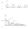
- Fig. 3 schematically the frequency spectrum of an in Fig. 2 shown pulse modulated signal shows.
- This in Fig. 2 shown pulse-modulated signal has a modulation frequency T and a modulation duration ⁇ 1.
- Fig. 3 By transformation of in Fig. 2 in a frequency domain, the signal represented in a time domain is obtained in Fig. 3 shown frequency spectrum.
- the spectrum itself has a minimum at the harmonic frequencies fh4, fh8 and fh12.
- the distance of these minima corresponds to the reciprocal of the modulation duration, ie the value 1 / ⁇ 1.
- the line S1 represents the envelope of the resulting transmission frequency spectrum, while the line SM shows a possible spectrum mask, such as this with increasing frequency allows a gradually decreasing amplitude of the frequencies contained in the transmission frequency spectrum.
- Fig. 3 represents only the upper (positive) half of the transmission frequency spectrum, which would have the same appearance in the negative region.
- the amplitude of the harmonic frequency fh3 would exceed the spectrum mask.
- Fig. 4 now shows a pulse modulated signal, which with the same modulation frequency T as the signal in Fig. 2 is modulated, but unlike the signal Fig. 2 has a different modulation duration ⁇ 2.
- Fig. 5 is the frequency spectrum of the signal off Fig. 4 applied. Since the harmonic frequencies fh1 to fh8 are determined by the value 1 / T, they have the same position as the harmonic frequencies fh1 to fh12 Fig. 3 , By changing the modulation period ⁇ 2, the frequency spectrum of the signal is off Fig. 4 however, minima at the harmonic frequencies fh3, fh6 and fh9. The envelope of this signal is marked S2.
- the envelopes S1 and S2 of the two frequency spectrums are off Fig. 3 and Fig. 5 applied, as well as an envelope S3. Since the signal with the modulation duration ⁇ 1 and the signal with the modulation duration ⁇ 2 according to the invention is only transmitted for a short period of time, ie the transmission frequency spectrum only occurs for a short period of time, the result of an averaging with a defined filter bandwidth and a time constant shows the envelope S3 that does not exceed the maximum permissible spectrum mask at any point.
Landscapes
- Engineering & Computer Science (AREA)
- Artificial Intelligence (AREA)
- Computer Vision & Pattern Recognition (AREA)
- Physics & Mathematics (AREA)
- General Physics & Mathematics (AREA)
- Theoretical Computer Science (AREA)
- Near-Field Transmission Systems (AREA)
- Radar Systems Or Details Thereof (AREA)
Claims (8)
- Procédé pour l'optimisation d'un spectre de fréquences d'émission d'une station d'écriture/lecture RFID pour une utilisation optimale du spectre de fréquences d'émission à l'intérieur d'un masque de spectre prédéterminé, dans lequel, afin de fournir le spectre de fréquences d'émission, la formation d'une valeur moyenne est réalisée, caractérisé en ce qu'on fait varier au moins un des paramètres de modulation influençant le spectre de fréquences d'émission à des intervalles temporels et, cela dans la mesure où on fait varier au moins un paramètre de modulation à l'intérieur des limites de tolérance de la norme technique respective, et en ce qu'un paramètre de modulation ou une combinaison de paramètres de modulation pour lesquels le masque de spectre est dépassé, est de nouveau réglé seulement après un certain temps qui est supérieur à la constante de temps de la formation de la valeur moyenne.
- Procédé selon la revendication 1, dans lequel comme paramètre de modulation on fait varier la fréquence de modulation et/ou la période de modulation et/ou la position de modulation et/ou le degré de modulation.
- Procédé selon la revendication 1 ou 2, caractérisé en ce que la variation d'au moins un paramètre de modulation est réalisée après chaque signal de modulation.
- Procédé selon la revendication 1 ou 2, caractérisé en ce que la variation d'au moins un paramètre de modulation est réalisée après chaque mot de données émis.
- Procédé selon la revendication 1 ou 2, caractérisé en ce que la variation d'au moins un paramètre de modulation est réalisée après au moins l'émission d'une commande.
- Procédé selon la revendication 1 ou 2, caractérisé en ce que la variation d'au moins un paramètre de modulation est réalisée après au moins un cycle de communication.
- Procédé selon l'une quelconque des revendications précédentes, caractérisé en ce que la variation d'au moins un paramètre de modulation est réalisée suite à une combinaison de différentes conditions temporelles.
- Procédé selon l'une quelconque des revendications précédentes, caractérisé en ce que la variation d'au moins un paramètre de modulation est réalisée de telle manière qu'au moins un minimum de l'enveloppe d'un deuxième spectre de fréquences suite à la variation, se trouve situé à une fréquence à laquelle l'enveloppe d'un premier spectre de fréquences a dépassé le masque de spectre.
Priority Applications (3)
| Application Number | Priority Date | Filing Date | Title |
|---|---|---|---|
| EP07111868A EP2012251B1 (fr) | 2007-07-05 | 2007-07-05 | Procédé destiné à l'optimisation du spectre de la fréquence d'émission d'une station d'écriture/lecture RFID |
| AT07111868T ATE494592T1 (de) | 2007-07-05 | 2007-07-05 | Verfahren zur optimierung des sendefrequenzspektrums einer rfid-schreib- /lesestation |
| DE502007006191T DE502007006191D1 (de) | 2007-07-05 | 2007-07-05 | Verfahren zur Optimierung des Sendefrequenzspektrums einer RFID-Schreib-/Lesestation |
Applications Claiming Priority (1)
| Application Number | Priority Date | Filing Date | Title |
|---|---|---|---|
| EP07111868A EP2012251B1 (fr) | 2007-07-05 | 2007-07-05 | Procédé destiné à l'optimisation du spectre de la fréquence d'émission d'une station d'écriture/lecture RFID |
Publications (2)
| Publication Number | Publication Date |
|---|---|
| EP2012251A1 EP2012251A1 (fr) | 2009-01-07 |
| EP2012251B1 true EP2012251B1 (fr) | 2011-01-05 |
Family
ID=38805570
Family Applications (1)
| Application Number | Title | Priority Date | Filing Date |
|---|---|---|---|
| EP07111868A Active EP2012251B1 (fr) | 2007-07-05 | 2007-07-05 | Procédé destiné à l'optimisation du spectre de la fréquence d'émission d'une station d'écriture/lecture RFID |
Country Status (3)
| Country | Link |
|---|---|
| EP (1) | EP2012251B1 (fr) |
| AT (1) | ATE494592T1 (fr) |
| DE (1) | DE502007006191D1 (fr) |
Family Cites Families (3)
| Publication number | Priority date | Publication date | Assignee | Title |
|---|---|---|---|---|
| WO2001035318A2 (fr) | 1999-11-09 | 2001-05-17 | Checkpoint Systems, Inc. | Processeur d'impulsion efficace de largeur de bande pour la communication de donnees d'identification de frequences radio |
| US7408466B2 (en) | 2004-04-13 | 2008-08-05 | Impinj, Inc. | Adjusting RFID waveform shape in view of detected RF energy |
| DE102004045918A1 (de) * | 2004-09-20 | 2006-03-23 | Feig Electronic Gmbh | Vorrichtung und Verfahren zur Analyse und Einstellung einer RFID Schreib-/Lesestation |
-
2007
- 2007-07-05 EP EP07111868A patent/EP2012251B1/fr active Active
- 2007-07-05 DE DE502007006191T patent/DE502007006191D1/de active Active
- 2007-07-05 AT AT07111868T patent/ATE494592T1/de active
Also Published As
| Publication number | Publication date |
|---|---|
| DE502007006191D1 (de) | 2011-02-17 |
| EP2012251A1 (fr) | 2009-01-07 |
| ATE494592T1 (de) | 2011-01-15 |
Similar Documents
| Publication | Publication Date | Title |
|---|---|---|
| EP0583690B1 (fr) | Carte à puce pourvue d'un détecteur d'intensité de champ | |
| EP0567889B1 (fr) | Système de transmission bidirectionnelle de données entre plusieurs stations fixés et une station mobile | |
| DE68920684T2 (de) | System zur Diskrimination von Signalen. | |
| EP1990755B1 (fr) | Procédé de fonctionnement d'une étiquette RFID dotée d'une localisation exacte | |
| DE19847135A1 (de) | Verfahren zum Lesen der in einem Transponder gespeicherten Daten und Transpondersystem zur Durchführung des Verfahrens | |
| EP1153362B1 (fr) | Systeme de transfert de donnees sans contact et procede pour le transfert de donnees sans contact | |
| DE10050878B4 (de) | Verfahren zur Übertragung von mehreren Informationssymbolen | |
| DE19731035B4 (de) | Verfahren zur Datenübertragung zwischen einem Schreib-Lesegerät und einem Transponder | |
| EP2012251B1 (fr) | Procédé destiné à l'optimisation du spectre de la fréquence d'émission d'une station d'écriture/lecture RFID | |
| DE10121855A1 (de) | Verfahren zur Übertragung von Daten | |
| DE29622767U1 (de) | Frequency-Hopping für passive und semi-passive Telemetrie- und Identifikationssysteme | |
| DE2808316A1 (de) | Befehlssignalgenerator fuer eine selbsttaetige kanalauswahlanordnung in einem in bezug aus sendestationen bewegenden rundfunkempfaenger | |
| WO2008064824A1 (fr) | Procédé de transmission sans fil de données entre une station de base et un transpondeur passif, ainsi que transpondeur passif | |
| DE69901665T2 (de) | Schreib/lesegerät zur nachrichtenübertragung mit transpondern, mit ersten und zweiten kodiermitteln | |
| DE10005503A1 (de) | Verfahren zur Erhöhung der Manipulationssicherheit bei einer bidirektionalen, kontaktlosen Datenübertragung | |
| DE10214113B4 (de) | Verfahren zum berührungslosen Austausch einer Sequenz von Datenbytes in einem Identifikationssystem | |
| DE19634134C1 (de) | Verfahren zum Übertragen von Daten zwischen einem Terminal und einem tragbaren Datenträger über eine drahtlose elektromagnetische Übertragungsstrecke | |
| DE102007028695A1 (de) | Verfahren und Vorrichtung zur Erzeugung eines amplituden-modulierten Signals | |
| DE102004031671B4 (de) | Modulator-Schaltkreis, Sende-/Empfangs-Einrichtung,Lese-Vorrichtung und Verfahren zum Bilden eines modulierten Signals | |
| EP2340512A2 (fr) | Unité transpondeur | |
| EP2362553B1 (fr) | Procédé de détermination d'un canal d'émission pour un système RFID | |
| DE102004045918A1 (de) | Vorrichtung und Verfahren zur Analyse und Einstellung einer RFID Schreib-/Lesestation | |
| DE2454311C3 (de) | Vorrichtung zur selbsttätigen Übertragung von Information von einem Informationsgeber zu einem Informationssuchempfänger | |
| DE69727034T2 (de) | Transpondersystem | |
| EP1136935B1 (fr) | Décodeur |
Legal Events
| Date | Code | Title | Description |
|---|---|---|---|
| PUAI | Public reference made under article 153(3) epc to a published international application that has entered the european phase |
Free format text: ORIGINAL CODE: 0009012 |
|
| AK | Designated contracting states |
Kind code of ref document: A1 Designated state(s): AT BE BG CH CY CZ DE DK EE ES FI FR GB GR HU IE IS IT LI LT LU LV MC MT NL PL PT RO SE SI SK TR |
|
| AX | Request for extension of the european patent |
Extension state: AL BA HR MK RS |
|
| 17P | Request for examination filed |
Effective date: 20090609 |
|
| AKX | Designation fees paid |
Designated state(s): AT BE BG CH CY CZ DE DK EE ES FI FR GB GR HU IE IS IT LI LT LU LV MC MT NL PL PT RO SE SI SK TR |
|
| 17Q | First examination report despatched |
Effective date: 20091130 |
|
| GRAP | Despatch of communication of intention to grant a patent |
Free format text: ORIGINAL CODE: EPIDOSNIGR1 |
|
| GRAC | Information related to communication of intention to grant a patent modified |
Free format text: ORIGINAL CODE: EPIDOSCIGR1 |
|
| GRAS | Grant fee paid |
Free format text: ORIGINAL CODE: EPIDOSNIGR3 |
|
| GRAA | (expected) grant |
Free format text: ORIGINAL CODE: 0009210 |
|
| AK | Designated contracting states |
Kind code of ref document: B1 Designated state(s): AT BE BG CH CY CZ DE DK EE ES FI FR GB GR HU IE IS IT LI LT LU LV MC MT NL PL PT RO SE SI SK TR |
|
| REG | Reference to a national code |
Ref country code: GB Ref legal event code: FG4D Free format text: NOT ENGLISH |
|
| REG | Reference to a national code |
Ref country code: CH Ref legal event code: EP |
|
| REG | Reference to a national code |
Ref country code: IE Ref legal event code: FG4D Free format text: LANGUAGE OF EP DOCUMENT: GERMAN |
|
| REF | Corresponds to: |
Ref document number: 502007006191 Country of ref document: DE Date of ref document: 20110217 Kind code of ref document: P |
|
| REG | Reference to a national code |
Ref country code: DE Ref legal event code: R096 Ref document number: 502007006191 Country of ref document: DE Effective date: 20110217 |
|
| REG | Reference to a national code |
Ref country code: NL Ref legal event code: VDEP Effective date: 20110105 |
|
| PG25 | Lapsed in a contracting state [announced via postgrant information from national office to epo] |
Ref country code: SI Free format text: LAPSE BECAUSE OF FAILURE TO SUBMIT A TRANSLATION OF THE DESCRIPTION OR TO PAY THE FEE WITHIN THE PRESCRIBED TIME-LIMIT Effective date: 20110105 |
|
| LTIE | Lt: invalidation of european patent or patent extension |
Effective date: 20110105 |
|
| PG25 | Lapsed in a contracting state [announced via postgrant information from national office to epo] |
Ref country code: ES Free format text: LAPSE BECAUSE OF FAILURE TO SUBMIT A TRANSLATION OF THE DESCRIPTION OR TO PAY THE FEE WITHIN THE PRESCRIBED TIME-LIMIT Effective date: 20110416 Ref country code: IS Free format text: LAPSE BECAUSE OF FAILURE TO SUBMIT A TRANSLATION OF THE DESCRIPTION OR TO PAY THE FEE WITHIN THE PRESCRIBED TIME-LIMIT Effective date: 20110505 Ref country code: LT Free format text: LAPSE BECAUSE OF FAILURE TO SUBMIT A TRANSLATION OF THE DESCRIPTION OR TO PAY THE FEE WITHIN THE PRESCRIBED TIME-LIMIT Effective date: 20110105 Ref country code: SE Free format text: LAPSE BECAUSE OF FAILURE TO SUBMIT A TRANSLATION OF THE DESCRIPTION OR TO PAY THE FEE WITHIN THE PRESCRIBED TIME-LIMIT Effective date: 20110105 Ref country code: PT Free format text: LAPSE BECAUSE OF FAILURE TO SUBMIT A TRANSLATION OF THE DESCRIPTION OR TO PAY THE FEE WITHIN THE PRESCRIBED TIME-LIMIT Effective date: 20110505 Ref country code: LV Free format text: LAPSE BECAUSE OF FAILURE TO SUBMIT A TRANSLATION OF THE DESCRIPTION OR TO PAY THE FEE WITHIN THE PRESCRIBED TIME-LIMIT Effective date: 20110105 Ref country code: GR Free format text: LAPSE BECAUSE OF FAILURE TO SUBMIT A TRANSLATION OF THE DESCRIPTION OR TO PAY THE FEE WITHIN THE PRESCRIBED TIME-LIMIT Effective date: 20110406 |
|
| REG | Reference to a national code |
Ref country code: IE Ref legal event code: FD4D |
|
| PG25 | Lapsed in a contracting state [announced via postgrant information from national office to epo] |
Ref country code: FI Free format text: LAPSE BECAUSE OF FAILURE TO SUBMIT A TRANSLATION OF THE DESCRIPTION OR TO PAY THE FEE WITHIN THE PRESCRIBED TIME-LIMIT Effective date: 20110105 Ref country code: PL Free format text: LAPSE BECAUSE OF FAILURE TO SUBMIT A TRANSLATION OF THE DESCRIPTION OR TO PAY THE FEE WITHIN THE PRESCRIBED TIME-LIMIT Effective date: 20110105 Ref country code: BG Free format text: LAPSE BECAUSE OF FAILURE TO SUBMIT A TRANSLATION OF THE DESCRIPTION OR TO PAY THE FEE WITHIN THE PRESCRIBED TIME-LIMIT Effective date: 20110405 Ref country code: NL Free format text: LAPSE BECAUSE OF FAILURE TO SUBMIT A TRANSLATION OF THE DESCRIPTION OR TO PAY THE FEE WITHIN THE PRESCRIBED TIME-LIMIT Effective date: 20110105 Ref country code: CY Free format text: LAPSE BECAUSE OF FAILURE TO SUBMIT A TRANSLATION OF THE DESCRIPTION OR TO PAY THE FEE WITHIN THE PRESCRIBED TIME-LIMIT Effective date: 20110105 |
|
| PG25 | Lapsed in a contracting state [announced via postgrant information from national office to epo] |
Ref country code: EE Free format text: LAPSE BECAUSE OF FAILURE TO SUBMIT A TRANSLATION OF THE DESCRIPTION OR TO PAY THE FEE WITHIN THE PRESCRIBED TIME-LIMIT Effective date: 20110105 Ref country code: IE Free format text: LAPSE BECAUSE OF FAILURE TO SUBMIT A TRANSLATION OF THE DESCRIPTION OR TO PAY THE FEE WITHIN THE PRESCRIBED TIME-LIMIT Effective date: 20110105 Ref country code: DK Free format text: LAPSE BECAUSE OF FAILURE TO SUBMIT A TRANSLATION OF THE DESCRIPTION OR TO PAY THE FEE WITHIN THE PRESCRIBED TIME-LIMIT Effective date: 20110105 |
|
| PLBE | No opposition filed within time limit |
Free format text: ORIGINAL CODE: 0009261 |
|
| STAA | Information on the status of an ep patent application or granted ep patent |
Free format text: STATUS: NO OPPOSITION FILED WITHIN TIME LIMIT |
|
| PG25 | Lapsed in a contracting state [announced via postgrant information from national office to epo] |
Ref country code: CZ Free format text: LAPSE BECAUSE OF FAILURE TO SUBMIT A TRANSLATION OF THE DESCRIPTION OR TO PAY THE FEE WITHIN THE PRESCRIBED TIME-LIMIT Effective date: 20110105 Ref country code: SK Free format text: LAPSE BECAUSE OF FAILURE TO SUBMIT A TRANSLATION OF THE DESCRIPTION OR TO PAY THE FEE WITHIN THE PRESCRIBED TIME-LIMIT Effective date: 20110105 Ref country code: RO Free format text: LAPSE BECAUSE OF FAILURE TO SUBMIT A TRANSLATION OF THE DESCRIPTION OR TO PAY THE FEE WITHIN THE PRESCRIBED TIME-LIMIT Effective date: 20110105 |
|
| 26N | No opposition filed |
Effective date: 20111006 |
|
| PG25 | Lapsed in a contracting state [announced via postgrant information from national office to epo] |
Ref country code: MT Free format text: LAPSE BECAUSE OF FAILURE TO SUBMIT A TRANSLATION OF THE DESCRIPTION OR TO PAY THE FEE WITHIN THE PRESCRIBED TIME-LIMIT Effective date: 20110105 |
|
| BERE | Be: lapsed |
Owner name: FEIG ELECTRONIC G.M.B.H. Effective date: 20110731 |
|
| REG | Reference to a national code |
Ref country code: DE Ref legal event code: R097 Ref document number: 502007006191 Country of ref document: DE Effective date: 20111006 |
|
| PG25 | Lapsed in a contracting state [announced via postgrant information from national office to epo] |
Ref country code: MC Free format text: LAPSE BECAUSE OF NON-PAYMENT OF DUE FEES Effective date: 20110731 |
|
| REG | Reference to a national code |
Ref country code: CH Ref legal event code: PL |
|
| PG25 | Lapsed in a contracting state [announced via postgrant information from national office to epo] |
Ref country code: CH Free format text: LAPSE BECAUSE OF NON-PAYMENT OF DUE FEES Effective date: 20110731 Ref country code: LI Free format text: LAPSE BECAUSE OF NON-PAYMENT OF DUE FEES Effective date: 20110731 Ref country code: BE Free format text: LAPSE BECAUSE OF NON-PAYMENT OF DUE FEES Effective date: 20110731 |
|
| PG25 | Lapsed in a contracting state [announced via postgrant information from national office to epo] |
Ref country code: LU Free format text: LAPSE BECAUSE OF NON-PAYMENT OF DUE FEES Effective date: 20110705 |
|
| REG | Reference to a national code |
Ref country code: AT Ref legal event code: MM01 Ref document number: 494592 Country of ref document: AT Kind code of ref document: T Effective date: 20120731 |
|
| PG25 | Lapsed in a contracting state [announced via postgrant information from national office to epo] |
Ref country code: TR Free format text: LAPSE BECAUSE OF FAILURE TO SUBMIT A TRANSLATION OF THE DESCRIPTION OR TO PAY THE FEE WITHIN THE PRESCRIBED TIME-LIMIT Effective date: 20110105 |
|
| PG25 | Lapsed in a contracting state [announced via postgrant information from national office to epo] |
Ref country code: AT Free format text: LAPSE BECAUSE OF NON-PAYMENT OF DUE FEES Effective date: 20120731 Ref country code: HU Free format text: LAPSE BECAUSE OF FAILURE TO SUBMIT A TRANSLATION OF THE DESCRIPTION OR TO PAY THE FEE WITHIN THE PRESCRIBED TIME-LIMIT Effective date: 20110105 |
|
| REG | Reference to a national code |
Ref country code: FR Ref legal event code: PLFP Year of fee payment: 10 |
|
| REG | Reference to a national code |
Ref country code: FR Ref legal event code: PLFP Year of fee payment: 11 |
|
| REG | Reference to a national code |
Ref country code: FR Ref legal event code: PLFP Year of fee payment: 12 |
|
| P01 | Opt-out of the competence of the unified patent court (upc) registered |
Effective date: 20230513 |
|
| PGFP | Annual fee paid to national office [announced via postgrant information from national office to epo] |
Ref country code: DE Payment date: 20240423 Year of fee payment: 18 |
|
| PGFP | Annual fee paid to national office [announced via postgrant information from national office to epo] |
Ref country code: GB Payment date: 20240723 Year of fee payment: 18 |
|
| PGFP | Annual fee paid to national office [announced via postgrant information from national office to epo] |
Ref country code: FR Payment date: 20240729 Year of fee payment: 18 |
|
| PGFP | Annual fee paid to national office [announced via postgrant information from national office to epo] |
Ref country code: IT Payment date: 20240725 Year of fee payment: 18 |
|
| REG | Reference to a national code |
Ref country code: DE Ref legal event code: R082 Ref document number: 502007006191 Country of ref document: DE |
|
| REG | Reference to a national code |
Ref country code: DE Ref legal event code: R119 Ref document number: 502007006191 Country of ref document: DE |
|
| GBPC | Gb: european patent ceased through non-payment of renewal fee |
Effective date: 20250705 |
|
| PG25 | Lapsed in a contracting state [announced via postgrant information from national office to epo] |
Ref country code: GB Free format text: LAPSE BECAUSE OF NON-PAYMENT OF DUE FEES Effective date: 20250705 |
|
| PG25 | Lapsed in a contracting state [announced via postgrant information from national office to epo] |
Ref country code: DE Free format text: LAPSE BECAUSE OF NON-PAYMENT OF DUE FEES Effective date: 20260203 |
|
| PG25 | Lapsed in a contracting state [announced via postgrant information from national office to epo] |
Ref country code: FR Free format text: LAPSE BECAUSE OF NON-PAYMENT OF DUE FEES Effective date: 20250731 |