EP2012377A1 - Batteriepack - Google Patents
Batteriepack Download PDFInfo
- Publication number
- EP2012377A1 EP2012377A1 EP06746838A EP06746838A EP2012377A1 EP 2012377 A1 EP2012377 A1 EP 2012377A1 EP 06746838 A EP06746838 A EP 06746838A EP 06746838 A EP06746838 A EP 06746838A EP 2012377 A1 EP2012377 A1 EP 2012377A1
- Authority
- EP
- European Patent Office
- Prior art keywords
- battery pack
- cover
- battery
- lateral surface
- housing
- Prior art date
- Legal status (The legal status is an assumption and is not a legal conclusion. Google has not performed a legal analysis and makes no representation as to the accuracy of the status listed.)
- Withdrawn
Links
Images




Classifications
-
- H—ELECTRICITY
- H01—ELECTRIC ELEMENTS
- H01M—PROCESSES OR MEANS, e.g. BATTERIES, FOR THE DIRECT CONVERSION OF CHEMICAL ENERGY INTO ELECTRICAL ENERGY
- H01M6/00—Primary cells; Manufacture thereof
- H01M6/50—Methods or arrangements for servicing or maintenance, e.g. for maintaining operating temperature
- H01M6/5044—Cells or batteries structurally combined with cell condition indicating means
-
- H—ELECTRICITY
- H01—ELECTRIC ELEMENTS
- H01M—PROCESSES OR MEANS, e.g. BATTERIES, FOR THE DIRECT CONVERSION OF CHEMICAL ENERGY INTO ELECTRICAL ENERGY
- H01M10/00—Secondary cells; Manufacture thereof
- H01M10/42—Methods or arrangements for servicing or maintenance of secondary cells or secondary half-cells
- H01M10/48—Accumulators combined with arrangements for measuring, testing or indicating the condition of cells, e.g. the level or density of the electrolyte
-
- H—ELECTRICITY
- H01—ELECTRIC ELEMENTS
- H01M—PROCESSES OR MEANS, e.g. BATTERIES, FOR THE DIRECT CONVERSION OF CHEMICAL ENERGY INTO ELECTRICAL ENERGY
- H01M50/00—Constructional details or processes of manufacture of the non-active parts of electrochemical cells other than fuel cells, e.g. hybrid cells
- H01M50/20—Mountings; Secondary casings or frames; Racks, modules or packs; Suspension devices; Shock absorbers; Transport or carrying devices; Holders
- H01M50/204—Racks, modules or packs for multiple batteries or multiple cells
- H01M50/207—Racks, modules or packs for multiple batteries or multiple cells characterised by their shape
- H01M50/209—Racks, modules or packs for multiple batteries or multiple cells characterised by their shape adapted for prismatic or rectangular cells
-
- Y—GENERAL TAGGING OF NEW TECHNOLOGICAL DEVELOPMENTS; GENERAL TAGGING OF CROSS-SECTIONAL TECHNOLOGIES SPANNING OVER SEVERAL SECTIONS OF THE IPC; TECHNICAL SUBJECTS COVERED BY FORMER USPC CROSS-REFERENCE ART COLLECTIONS [XRACs] AND DIGESTS
- Y02—TECHNOLOGIES OR APPLICATIONS FOR MITIGATION OR ADAPTATION AGAINST CLIMATE CHANGE
- Y02E—REDUCTION OF GREENHOUSE GAS [GHG] EMISSIONS, RELATED TO ENERGY GENERATION, TRANSMISSION OR DISTRIBUTION
- Y02E60/00—Enabling technologies; Technologies with a potential or indirect contribution to GHG emissions mitigation
- Y02E60/10—Energy storage using batteries
Definitions
- the present invention is relates to a battery pack in which cartridge-like batteries are stored in an attachable and removable manner.
- a battery cell or a pack combining a plurality of battery cells and a substrate are stored between a rear cover and a top cover, which are secured to each other by welding, adhesive bonding, or the like, as shown in e.g. patent document 1.
- covers divided in two are pressurized and heated by ultrasound to be melted and solidified for joining.
- the battery pack formed as described above has such features that it can be configured to have a simple structure and to be compact and staunch as compared with covers that are screw-fastened to each other for fixation and thus can be manufactured inexpensively.
- Patent Document 1 International Publication WO01/073879
- the covers joined together by ultrasound welding or the like can make the battery pack staunch; however, the covers cannot be opened in the event that the battery cell incorporated may cause trouble or the like. Because of relatively expensive, the battery pack has needed to be easily maintained.
- a battery pack of the present invention includes: a housing having four circumferential lateral surfaces one of which is opened; a lid body opening and closing the opened lateral surface of the housing; and a plurality of batteries attached to and detached from the inside of the housing.
- the housing is formed to be divided in two portions one of which is a top cover having the opened lateral surface and another one of the two portions is a rear cover mounted with a control substrate thereon.
- the inside of the top cover is partitioned by a partition plate into upper and lower battery-storing portions in each of which a cartridge-like battery can be stored.
- the lid body is opened and closed to open and close the open lateral surface of the housing so that the cartridge-like battery can be attached and removed.
- Such a configuration not only can achieve high-capacity by use of a plurality of batteries but can facilitate maintenance such as replacement or the like.
- the control substrate is mounted on the rear cover, a substrate cover is provided to cover the control substrate, and a projecting portion is provided on the substrate cover so as to project upward to carry the partition plate.
- the battery pack of this type is usually provided with a self-capacity output circuit and with a self-capacity output terminal to output remaining capacity to be displayed in the finder of a video camera or the like.
- the substrate adapted to control such data output is covered by the substrate cover so as not to be affected by other constituent elements inside the housing.
- a groove-like portion is provided at an end-edge of the opened lateral surface of the upper housing so as to attach thereto and remove therefrom the lid body by linearly sliding the lid body along a circumferential direction, and a recessed portion is provided at an end-edge of the opened lateral surface of the lower housing so as to be able to be fitted to a small projecting portion provided on the lid body.
- the lid body can easily be moved along the edge of the open lateral surface, can easily be positioned and can be made hard to disengage.
- a taking-out tub portion is provided on the opened lateral surface side of the partition plate so as to rise therefrom.
- This tub portion can control the release of the battery cartridge.
- the tub portion is configured to face the rear cover side, it usually restrains the movement of the battery cartridge mounted on the substrate cover and makes it possible for the battery cartridge to be freely movable only when the lid body is removed.
- a positioning projecting portion is provided on the partition plate so as to be abutted against an inner surface of a top surface of the top cover.
- an electrical and mechanical portion to be connected to other equipment such as a TV camera is provided on a rear surface of the rear cover and one lateral surface, and an inclined surface is provided at both lateral edges of the rear cover to prevent interference with the other equipment such as a TV camera.
- Other equipment such as a TV camera is formed with various projections due to some convenience for the manufacturer thereof. In particular, projections adapted to restrict the lateral surface position of the battery pack often hinder another company's equipment from being attached. However, since the inclined surface portion is provided, situations of avoiding such hindrance increase.
- the battery pack of the present invention has effects such that the cartridge-like batteries can simply be attached and removed, use of a plurality of the batteries can achieve high-capacity and operation such as the attachment-removal and replacement of the battery can be facilitated.
- FIG. 1 is an exploded perspective view of a battery pack according to an embodiment of the present invention.
- a battery pack 1 of the present embodiment mainly includes a top cover 2, a rear cover 3, a slide cover 5, and a plurality of cartridge-like batteries (hereinafter, referred to as the battery cartridges) 6a and 6b.
- the top cover 2 with four circumferential lateral surfaces one of which is opened and the rear cover 3 constitute a housing.
- the slide cover 5 serves as a lid body that opens and closes an open lateral surface 4 of the housing constituted by the top cover 2 and rear cover 3.
- the battery cartridges 6a, 6b are removably attached to the inside of the housing constituted by the top cover 2 and rear cover 3.
- the housing is formed to be divided in two portions one of which is the top cover 2 having the open lateral surface 4 and another one of the two portions is the rear cover 3 mounted with a control substrate 7 thereon.
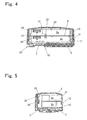
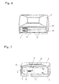
- the inside of the top cover 2 is vertically divided in two by a partition plate 8 to form battery-storing portions 9a and 9b which can store the battery cartridges 6a and 6b, respectively (see Figs. 4, 5 and 7 , etc.)
- the open lateral surface 4 of the housing is opened and closed by opening and closing the slide cover 5 so that the battery cartridges 6a, 6b can individually be attached and removed.
- maintenance such as replacement or the like can be performed easily and simply.
- the control substrate 7 is mounted on the rear cover 3 as described above and covered by a substrate cover 10. Pair of projecting wall portions 11, 11 are provided on the substrate cover 10 so as to project upward therefrom to carry the lower surface of the partition plate 8. Needless to say, the position where the projecting wall portions are provided corresponds to that of both ends of the open lateral surface 4.
- the control substrate 7 exercises control for outputting remaining capacity to be displayed in the finder of a video camera or the like, which is usually performed by battery packs of this type. To that end, the control substrate 7 is provided with a self-capacity output circuit and with self-capacity output terminals. The substrate 7 adapted to control such data output is covered by the substrate cover 10 so as not to be affected by other constituent elements inside the housing.
- a taking-out release tub 12 is provided at an edge of the partition plate 8 on the side of the open lateral surface 4.
- This release tub 12 is provided at the edge of the partition plate 8 in a vertically turnable manner so as to control the release of the battery cartridges 6a, 6b, particularly, of the battery cartridge 6b on the lower side in the figure. That is to say, for example, the release tub 12 may usually face the rear cover 3 and the battery cartridge 6b may be inserted by lifting the release tub 12 when attached. In such a configuration, the movement of the lower side battery cartridge 6b mounted on the substrate cover 10 is usually restrained but it can be made free only when the slide cover 5 is removed.
- pair of positioning projecting walls 13, 13 are provided on the partition plate 8 so as to be abutted against the internal top surface of the top cover 2.
- the partition plate 8 is surely positioned by these projecting walls 13, 13 and by the projecting wall portions 11, 11 so that the respective battery-storing portions 9a, 9b of the battery cartridges 6a, 6b are accurately defined in the housing.
- a groove-like portion 14 is provided at an edge portion, facing the open lateral surface 4, of the top cover 2 constituting part of the housing.
- the groove-like portion 14 is adapted to attach thereto and detach therefrom the slide cover 5 by linearly sliding the slide cover 5 along the outer circumferential direction.
- a projecting ridge 15 is provided at an upper edge and an end-edge of the slide cover 5 so as to be able to be fitted to the groove-like portion 14, the end-edge being the forefront when the slide cover 5 is moved in the closing direction.
- a recessed portion 17 is provided on an end-edge, facing the open lateral surface 4, of the rear cover 3 so as to be able to fitted to a small projection 16 provided at a lower edge, in the figure, of the slide cover 5 (see Fig. 7 ).
- reference numeral 18 denotes a locking screw.
- a folded portion 19 is provided at an end-edge of the slide cover 5, the end-edge being the forefront when the slide cover 5 is moved in the closing direction.
- a portion 20, of the top cover 2, corresponding to the folded portion 19 is notched to be recessed.
- a locking screw receiver 21 is provided at an edge of the portion 20. The locking screw 18 is screwed to the locking screw receiver 21 to secure the slide cover 5.
- An LED display section 23 for displaying a remaining level or the like and a push button 24 for performing operation of displaying and checking a remaining level are provided on a surface 22, of the top cover 2, opposed to the open lateral surface 4.
- a receiving plate 25 for a substrate or the like described later is provided at an edge, opposite to the open lateral surface 4, of the rear cover 3, to rise therefrom along the inner surface side of the above-mentioned surface 22.
- An LED substrate 26, an LED substrate guide 27 and a push button receiver 28 are provided on the receiving plate 25 on the side of the surface 22.
- a pair of battery contact connectors 29, 29 are provided to face the side opposite to the surface 22, i.e., to face the inside of the housing.
- a boss 30 for positioning or indexing the LED substrate guide 27 is provided at a generally central portion of the receiving plate 25.
- reference numeral 31 in the figure denotes a hook provided to restrict a thrusting-in position of the upper battery cartridge 6a.
- electrical and mechanical portions (a V-shaped locking plate 32, terminal portions 33 and the like) to be connected to other equipment such as a TV camera or the like are provided on a rear surface of the rear cover 3 and on a lateral surface 3a which is a bottom surface in the figure.
- inclined surface portions 34, 34 are provided at both lateral edges of the rear surface of the rear cover 3 to prevent interference with the projections of other equipment such as a TV camera or the like. Since the electrical and mechanical portions to be connected to other equipment such as a TV camera are well-known mechanisms, their explanations are omitted.
- the inclined surface portion 34 is provided to extend to the approximate middle of the rear surface of the rear cover 3.
- the inclined surface portion 34 is formed such that it is broad on the side of the lateral surface 3a which is the bottom surface and is more narrowed in width as it goes to the longitudinal central portion of the battery pack 1.
- the inclined surface portion 34 disappears at the generally central portion.
- Other equipment such as a TV camera is formed with various projections due to some convenience for the manufacturer thereof. In particular, projections adapted to restrict the lateral surface position of the battery pack often hinder another company's equipment from being attached.
- the inclined surface portions 34 are provided at both the lateral edges of the rear cover 3 as described above, situations of avoiding such hindrance increase. Needless to say, the shape of the inclined surface 34 can appropriately be modified.
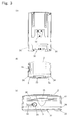
- the shape of the battery pack 1 according to the present embodiment is further described with reference to Fig. 2 .
- Both the upper edges of the top cover 2, the lateral surface 22 and the slide cover 5 are slightly curved and recessed only in the vicinity of the longitudinal center of the battery pack 1.
- the recessed portion 35 is formed parabolic as shown in Fig. 1 ; however, it may be appropriately formed. This is because the battery pack 1 can easily be grabbed by a person's hand compared with the case where the battery pack 1 formed of simple flat surfaces.
- a plurality of projecting ridges 36 are provided at the recessed portion 35 as slip stoppers acting when the battery pack 1 is grabbed so as to straddle the recessed portion 35.
- a recessed portion may be provided instead of the projecting ridges 36.
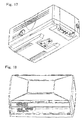
- the upper surface of the top cover 2 is formed like a truncated pyramid with low height. This is because of making it easy to grab the battery pack 1.
Landscapes
- Chemical & Material Sciences (AREA)
- Chemical Kinetics & Catalysis (AREA)
- Electrochemistry (AREA)
- General Chemical & Material Sciences (AREA)
- Engineering & Computer Science (AREA)
- Manufacturing & Machinery (AREA)
- Battery Mounting, Suspending (AREA)
Applications Claiming Priority (3)
| Application Number | Priority Date | Filing Date | Title |
|---|---|---|---|
| JP2006010208 | 2006-04-20 | ||
| JP2006118785A JP5147193B2 (ja) | 2006-04-24 | 2006-04-24 | バッテリパック |
| PCT/JP2006/310459 WO2007122738A1 (ja) | 2006-04-20 | 2006-05-25 | バッテリパック |
Publications (2)
| Publication Number | Publication Date |
|---|---|
| EP2012377A1 true EP2012377A1 (de) | 2009-01-07 |
| EP2012377A4 EP2012377A4 (de) | 2015-02-11 |
Family
ID=38624666
Family Applications (1)
| Application Number | Title | Priority Date | Filing Date |
|---|---|---|---|
| EP06746838.9A Withdrawn EP2012377A4 (de) | 2006-04-20 | 2006-05-25 | Batteriepack |
Country Status (3)
| Country | Link |
|---|---|
| US (1) | US8420243B2 (de) |
| EP (1) | EP2012377A4 (de) |
| WO (1) | WO2007122738A1 (de) |
Cited By (1)
| Publication number | Priority date | Publication date | Assignee | Title |
|---|---|---|---|---|
| EP3166160A4 (de) * | 2015-02-05 | 2017-12-13 | LG Chem, Ltd. | Kompaktes sekundärbatteriemodul und sekundärbatteriepack damit |
Families Citing this family (3)
| Publication number | Priority date | Publication date | Assignee | Title |
|---|---|---|---|---|
| JP5531503B2 (ja) * | 2009-08-21 | 2014-06-25 | ソニー株式会社 | 電子機器、及びバッテリパックの装着方法 |
| KR101511950B1 (ko) | 2012-10-29 | 2015-04-14 | 주식회사 엘지화학 | Pcb 상에 led 소자를 포함하고 있는 전지모듈 |
| KR101808310B1 (ko) * | 2014-12-24 | 2017-12-12 | 주식회사 엘지화학 | Bms 통합형 컴팩트 이차전지 모듈 |
Family Cites Families (6)
| Publication number | Priority date | Publication date | Assignee | Title |
|---|---|---|---|---|
| US5626979A (en) * | 1994-04-08 | 1997-05-06 | Sony Corporation | Battery device and electronic equipment employing the battery device as power source |
| US5534366A (en) * | 1995-11-22 | 1996-07-09 | Motorola, Inc. | Modular battery pack |
| JPH11354089A (ja) * | 1998-06-09 | 1999-12-24 | Matsushita Electric Ind Co Ltd | 電池パック及びその製造方法 |
| US6835481B2 (en) | 2000-03-29 | 2004-12-28 | Idatech, Llc | Fuel cell system with load management |
| JP3614158B2 (ja) | 2002-08-21 | 2005-01-26 | ソニー株式会社 | バッテリーパック |
| JP3882818B2 (ja) * | 2004-01-15 | 2007-02-21 | ソニー株式会社 | 電池パック |
-
2006
- 2006-05-25 US US12/226,427 patent/US8420243B2/en not_active Expired - Fee Related
- 2006-05-25 EP EP06746838.9A patent/EP2012377A4/de not_active Withdrawn
- 2006-05-25 WO PCT/JP2006/310459 patent/WO2007122738A1/ja not_active Ceased
Cited By (2)
| Publication number | Priority date | Publication date | Assignee | Title |
|---|---|---|---|---|
| EP3166160A4 (de) * | 2015-02-05 | 2017-12-13 | LG Chem, Ltd. | Kompaktes sekundärbatteriemodul und sekundärbatteriepack damit |
| US10680213B2 (en) | 2015-02-05 | 2020-06-09 | Lg Chem, Ltd. | Compact secondary battery module and secondary battery pack using same |
Also Published As
| Publication number | Publication date |
|---|---|
| EP2012377A4 (de) | 2015-02-11 |
| WO2007122738A1 (ja) | 2007-11-01 |
| US20100310915A1 (en) | 2010-12-09 |
| US8420243B2 (en) | 2013-04-16 |
Similar Documents
| Publication | Publication Date | Title |
|---|---|---|
| JP3160044U (ja) | 電源供給装置 | |
| JP4232851B2 (ja) | バッテリー装置 | |
| EP2131415B1 (de) | Batterie mit einem Paar Griffanordnungen | |
| KR101122943B1 (ko) | 배터리 장치 및 전자 기기 | |
| KR20000062557A (ko) | 배터리 팩, 배터리 장착 장치, 전력 공급 장치 및, 전자기기 | |
| JP3637625B2 (ja) | バッテリ装置及びこのバッテリ装置が装着される電子機器 | |
| JPH04308652A (ja) | バッテリーパック | |
| US20170040574A1 (en) | Battery pack | |
| JP6943535B2 (ja) | 電池ケース | |
| EP1831941B1 (de) | Batteriehülle | |
| JPH04144056A (ja) | 電子機器 | |
| US8420243B2 (en) | Battery pack | |
| WO2005096413A1 (ja) | バッテリー装置 | |
| JP2017068972A (ja) | 電池パック | |
| JP2007324032A (ja) | 電池収納ケース | |
| JP5147193B2 (ja) | バッテリパック | |
| JP2004327206A (ja) | 電池パック | |
| JP5919904B2 (ja) | 電池パック | |
| JP5058618B2 (ja) | 電池パック | |
| JP5062660B2 (ja) | 電池収納筐体および電子機器 | |
| WO2016129204A1 (ja) | 電子機器 | |
| CN107591499A (zh) | 自行车用组件 | |
| JPH11307072A (ja) | バッテリーパック誤挿入防止装置 | |
| JP2004022275A (ja) | 電池格納構造 | |
| JP4001144B2 (ja) | Dcアダプタ及びこれを用いた電子機器 |
Legal Events
| Date | Code | Title | Description |
|---|---|---|---|
| PUAI | Public reference made under article 153(3) epc to a published international application that has entered the european phase |
Free format text: ORIGINAL CODE: 0009012 |
|
| 17P | Request for examination filed |
Effective date: 20081120 |
|
| AK | Designated contracting states |
Kind code of ref document: A1 Designated state(s): AT BE BG CH CY CZ DE DK EE ES FI FR GB GR HU IE IS IT LI LT LU LV MC NL PL PT RO SE SI SK TR |
|
| AX | Request for extension of the european patent |
Extension state: AL BA HR MK YU |
|
| DAX | Request for extension of the european patent (deleted) | ||
| A4 | Supplementary search report drawn up and despatched |
Effective date: 20150113 |
|
| RIC1 | Information provided on ipc code assigned before grant |
Ipc: H01M 2/10 20060101AFI20150107BHEP |
|
| STAA | Information on the status of an ep patent application or granted ep patent |
Free format text: STATUS: THE APPLICATION IS DEEMED TO BE WITHDRAWN |
|
| 18D | Application deemed to be withdrawn |
Effective date: 20150811 |