EP2012393B1 - Elément de contact pour montage en surface - Google Patents
Elément de contact pour montage en surface Download PDFInfo
- Publication number
- EP2012393B1 EP2012393B1 EP08012177A EP08012177A EP2012393B1 EP 2012393 B1 EP2012393 B1 EP 2012393B1 EP 08012177 A EP08012177 A EP 08012177A EP 08012177 A EP08012177 A EP 08012177A EP 2012393 B1 EP2012393 B1 EP 2012393B1
- Authority
- EP
- European Patent Office
- Prior art keywords
- coil spring
- contact member
- surface mount
- mount contact
- protrusion
- Prior art date
- Legal status (The legal status is an assumption and is not a legal conclusion. Google has not performed a legal analysis and makes no representation as to the accuracy of the status listed.)
- Active
Links
Images



Classifications
-
- H—ELECTRICITY
- H01—ELECTRIC ELEMENTS
- H01R—ELECTRICALLY-CONDUCTIVE CONNECTIONS; STRUCTURAL ASSOCIATIONS OF A PLURALITY OF MUTUALLY-INSULATED ELECTRICAL CONNECTING ELEMENTS; COUPLING DEVICES; CURRENT COLLECTORS
- H01R13/00—Details of coupling devices of the kinds covered by groups H01R12/70 or H01R24/00 - H01R33/00
- H01R13/02—Contact members
- H01R13/22—Contacts for co-operating by abutting
- H01R13/24—Contacts for co-operating by abutting resilient; resiliently-mounted
- H01R13/2407—Contacts for co-operating by abutting resilient; resiliently-mounted characterized by the resilient means
- H01R13/2421—Contacts for co-operating by abutting resilient; resiliently-mounted characterized by the resilient means using coil springs
-
- Y—GENERAL TAGGING OF NEW TECHNOLOGICAL DEVELOPMENTS; GENERAL TAGGING OF CROSS-SECTIONAL TECHNOLOGIES SPANNING OVER SEVERAL SECTIONS OF THE IPC; TECHNICAL SUBJECTS COVERED BY FORMER USPC CROSS-REFERENCE ART COLLECTIONS [XRACs] AND DIGESTS
- Y10—TECHNICAL SUBJECTS COVERED BY FORMER USPC
- Y10S—TECHNICAL SUBJECTS COVERED BY FORMER USPC CROSS-REFERENCE ART COLLECTIONS [XRACs] AND DIGESTS
- Y10S439/00—Electrical connectors
- Y10S439/94—Electrical connectors including provision for mechanical lifting or manipulation, e.g. for vacuum lifting
Definitions
- This invention belongs to a technical field of a surface mount contact member to be mounted on a surface of a printed circuit board in order to achieve conduction between the printed circuit board and, for example, a housing.
- a surface mount contact member to be mounted on a surface of the printed circuit board includes a coil spring connector provided with two coil springs and an insulating holder that holds the two coil springs apart, as disclosed in Unexamined Japanese Patent Publication No. 2002-170617 .
- a flat surface formed on the holder between the two coil springs is used as a nozzle suction surface to be sucked by a suction nozzle.
- GB-A-2 392 322 discloses a pin type terminal for a printed circuit board having a tubular portion made of a conductive material, a spring stored in the tubular portion, a contact pin supported slidably and in a conductive state in the tubular portion and urged by the spring to have a tip end protruded from one end of the tubular portion, and a connection portion electrically connecting the tubular portion to a contact terminal on a printed circuit board.
- the flat surface between the two coil springs can be sucked by the suction nozzle for automatic mounting.
- the coil spring connector is constituted of two (or more) coil springs and the insulating holder, a constitution with only a single coil spring, that is, reduction in number of components, has been desired.
- the surface mount contact member of the first aspect is mounted on a surface of the printed circuit board with its soldering surface soldered on the printed circuit board.
- Soldering is not limited only to the soldering surface. For example, not only the soldering surface but the side surface and so on of the metal base may be soldered.
- the metal base is provided with the nozzle suction surface to be sucked by the suction nozzle, other than the soldering surface.
- the soldering surface is faced downward when the nozzle auction surface is faced upward.
- the coil spring is attached to the metal base in an electrically conductive manner with the nozzle suction surface being exposed to the inner peripheral side of the coil spring. Therefore, automatic mounting of the contact member is achieved by inserting the suction nozzle through the interior of the coil spring and sucking the nozzle suction surface by the suction nozzle.
- the contact point is made of a coil spring, no plastic deformation but mere elastic deformation occurs even if the contact point is touched by a worker or other members. Also, the contact point made of a coil spring is unlikely to be damaged due to loss of spring elasticity even if repetitively used multiple times.
- the nozzle suction surface is the top surface of the protrusion provided to stand on the base portion.
- the coil spring is fitted over the protrusion. Therefore, for example, since no labor such as welding is required, operation to attach the coil spring to the metal base is easy.
- the coil spring has an opening only sufficient for the suction nozzle to pass through. Accordingly, the surface mount contact member of the third aspect is suitable to be sucked by the suction nozzle.
- the coil spring is fitted over the protrusion provided on the metal base, and a reverse section is provided at an upper end of the protrusion in order to inhibit the coil spring from coming off. Accordingly, the surface mount contact member of the fourth aspect can reliably inhibit drop off of the coil spring.
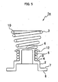
- a surface mount contact member 1 of the present embodiment includes a metal base 2 and a coil spring 3.
- the metal base 2 is formed of sheet metal such as brass, phosphor bronze, beryllium copper, and stainless steel.
- the coil spring 3 is formed of wire such as piano wire, beryllium copper, and stainless steel. Tinning or others may be applied to both the metal base 2 and the coil spring 3.
- the metal base 2 is provided with a rectangular base portion 4.
- a protrusion 5 is provided to stand in a center part of the base portion 4.
- the protrusion 5 has a cylindrical shape, whose top surface 6 is parallel to the surface of the base portion 4.
- the top surface 6 is used as a nozzle suction surface.
- Leg portions 7 extend from two mutually parallel sides of the base portion 4.
- the leg portions 7 are formed by bending the base portion 4 at a right angle so as to extend in a direction opposite to a protruding direction of the protrusion 5.
- the leg portions 7 are further bent at their ends at a right angle.
- the undersurfaces of the bent ends, which are parallel to the surface of the base portion 4, are used as soldering surfaces 8. That is, the top surface 6 and the soldering surfaces 8 are disposed such that the base portion 4 is located between the top surface 6 and the soldering surfaces 8.
- the base portion 4 (the surface), the top surface 6, and the soldering surfaces 8 are parallel to one another. As seen from FIG. 2 , when the top surface 6 is faced upward, the soldering surfaces 8 are faced downward.
- the above exemplified wire is formed into the coil spring 3 as shown in FIGS. 1A-1F , 2 and 3 .
- the above exemplified sheet metal is pressed into the metal base 2 as shown in FIGS. 1A-1F , 2 and 3 .
- a lower half of the coil spring 3 is then fitted over the protrusion 5 thereby to produce the surface mount contact member 1.
- the surface mount contact member 1 is gilded after the fitting of the coil spring 3 over the protrusion 5 in order to ensure conductivity of the surface of the surface mount contact member 1 and to prevent rust.
- the surface mount contact member 1 is housed in a recess formed by embossment of an emboss tape (emboss packaged) for shipping.
- the emboss packaged surface mount contact member 1 is provided to an automatic mounting apparatus. As seen in FIGS. 1A and 2 , since the coil spring 3 is fitted over the protrusion 5 (the metal base 2) with the top surface 6 of the protrusion 5 exposed to the inner peripheral side of the coil spring 3, a suction nozzle 11 of the automatic mounting apparatus can be inserted through the inner peripheral side of the horn of the coil spring 3 as shown in FIG. 3 to suck the top surface 6 of the protrusion 5.
- the surface mount contact member 1 is taken out of the recess formed by embossment by nozzle suction, automatically mounted on a printed circuit board, and then soldered onto the printed circuit board at the soldering surfaces 8 by reflow soldering for surface mounting.
- the base portion 4 has a rectangular shape.
- the coil spring 3 is fitted over the protrusion 5 provided to stand in the center of the base portion 4.
- a pair of leg portions 7 extend from two mutually parallel sides of the base portion 4.
- the coil spring 3 attached to the metal base 2 functions as a contact point and is brought into pressurized contact with a different conducting body (for example, a housing or other printed circuit board) from the printed circuit board having the surface mount contact member 1 soldered thereon. At that time, pressurized contact between the coil spring 3 and the housing or the like is maintained by compression of the coil spring 3.
- a different conducting body for example, a housing or other printed circuit board
- the contact point of the surface mount contact member 1 is made of the coil spring 3, no plastic deformation but mere elastic deformation occurs even if the contact point is touched by a worker or other members. Also, the contact point as the coil spring 3 is unlikely to be damaged due to loss of spring elasticity upon multiple repetition of use.
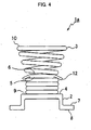
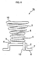
- a surface mount contact member 1b of the present embodiment is provided with a latch portion 13 formed by bending a tip on the side of the lower end 9 of the coil spring 3.
- the latch portion 13 is caught at an end section of the base portion 4.
- the surface mount contact member 1b has the same constitution with the surface mount contact member 1 of the first embodiment except for the latch portion 13.
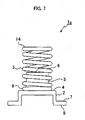
- a surface mount contact member 1c of the present embodiment is provided with the coil spring 3 which is not formed into a horn and has the same inner diameter from the lower end 9 through an upper end 14.
- the surface mount contact member 1c has the same constitution with the surface mount contact member 1 of the first embodiment except for absence of variation in diameter of turns of the coil spring 3.
- a surface mount contact member 1d is provided with the coil spring 3 having smaller diameters of upper-half turns on the side of an upper end 15.
- the surface mount contact member 1d has the same constitution with the surface mount contact member 1 of the first embodiment except for the spiral form of the coil spring 3.
Landscapes
- Coupling Device And Connection With Printed Circuit (AREA)
- Springs (AREA)
Claims (4)
- Organe de contact pour montage en surface qui inclut une base en métal (4) munie d'une surface d'aspiration par buse (6) pour aspiration par une buse d'aspiration et une surface de brasage (8) qui peut être brasée et est tournée vers le bas lorsque la surface d'aspiration par buse (6) est tournée vers le haut, caractérisé en ce que l'organe de contact pour montage en surface inclut un ressort à enroulement conducteur (3) attaché à la base en métal (4) d'une manière électriquement conductrice avec la surface d'aspiration par buse (6) exposée vers un côté périphérique interne du ressort à enroulement (3).
- Organe de contact pour montage en surface selon la revendication 1, dans lequel la surface d'aspiration par buse (6) est une surface supérieure d'une protubérance (5) amenée à se trouver sur une portion de base de la base en métal (4), le ressort à enroulement (3) est ajusté sur la protubérance, et la surface de brasage (8) est prévue sur une portion de patte (7) s'étendant dans une direction opposée à la protubérance.
- Organe de contact pour montage en surface selon la revendication 1, dans lequel le ressort à enroulement (3) comporte une ouverture seulement suffisante pour que la buse d'aspiration passe au travers.
- Organe de contact pour montage en surface selon la revendication 1, dans lequel le ressort à enroulement (3) est ajusté sur une protubérance prévue sur la base en métal (4), et une section inverse est disposée dans une extrémité supérieure de la protubérance afin d'inhiber le dégagement du ressort à enroulement (3).
Applications Claiming Priority (2)
| Application Number | Priority Date | Filing Date | Title |
|---|---|---|---|
| JP2007178605 | 2007-07-06 | ||
| JP2008080792A JP4868464B2 (ja) | 2007-07-06 | 2008-03-26 | 表面実装コンタクト |
Publications (2)
| Publication Number | Publication Date |
|---|---|
| EP2012393A1 EP2012393A1 (fr) | 2009-01-07 |
| EP2012393B1 true EP2012393B1 (fr) | 2011-08-03 |
Family
ID=39705334
Family Applications (1)
| Application Number | Title | Priority Date | Filing Date |
|---|---|---|---|
| EP08012177A Active EP2012393B1 (fr) | 2007-07-06 | 2008-07-05 | Elément de contact pour montage en surface |
Country Status (2)
| Country | Link |
|---|---|
| US (1) | US7503774B2 (fr) |
| EP (1) | EP2012393B1 (fr) |
Families Citing this family (10)
| Publication number | Priority date | Publication date | Assignee | Title |
|---|---|---|---|---|
| CN201138899Y (zh) * | 2007-12-12 | 2008-10-22 | 鸿富锦精密工业(深圳)有限公司 | 电子装置壳体 |
| US7736202B1 (en) | 2009-01-14 | 2010-06-15 | Gm Global Technology Operations, Inc. | Contact assembly for attachment to an electronics module |
| US7874880B2 (en) * | 2009-02-26 | 2011-01-25 | Ironwood Electronics, Inc. | Adapter apparatus with sleeve spring contacts |
| FI20115775A0 (fi) * | 2011-07-29 | 2011-07-29 | Salcomp Oyj | Sähköinen kontaktilaite |
| US20150351455A1 (en) * | 2012-12-11 | 2015-12-10 | Kimree Hi-Tech Inc. | Electronic cigarette and electronic cigarette device thereof |
| US20140165378A1 (en) | 2012-12-13 | 2014-06-19 | International Business Machines Corporation | Electronic component retainers |
| WO2017152959A1 (fr) * | 2016-03-08 | 2017-09-14 | Rosenberger Hochfrequenztechnik Gmbh & Co. Kg | Pointe à ressort |
| DE102018123994B4 (de) * | 2018-09-28 | 2022-05-25 | Knorr-Bremse Systeme für Nutzfahrzeuge GmbH | Kontaktiervorrichtung zum federbaren Kontaktieren einer Platine mit einem Kontaktelement für eine Magnetspule oder einen Sensor für ein Fahrzeugsystem, Fahrzeugsystem mit einer Kontaktiervorrichtung und Verfahren zum Herstellen einer Kontaktiervorrichtung |
| DE102020105298A1 (de) * | 2020-02-28 | 2021-09-02 | Knorr-Bremse Systeme für Nutzfahrzeuge GmbH | Leiterplatte mit einer Kontaktstelle |
| DE102020002076A1 (de) * | 2020-04-01 | 2021-10-07 | Kostal Automobil Elektrik Gmbh & Co. Kg | Axial federnder Einpresskontaktstift |
Family Cites Families (8)
| Publication number | Priority date | Publication date | Assignee | Title |
|---|---|---|---|---|
| US5189638A (en) * | 1990-04-26 | 1993-02-23 | Mitsubishi Denki Kabushiki Kaisha | Portable semiconductor memory device |
| JPH08167017A (ja) * | 1994-12-14 | 1996-06-25 | Mitsubishi Electric Corp | Icカード |
| CN1101068C (zh) | 1997-03-26 | 2003-02-05 | 柯克音响有限公司 | 一种接触装置及其处理工具 |
| JP2000149092A (ja) * | 1998-11-13 | 2000-05-30 | Nippon Conlux Co Ltd | シート材搬送装置 |
| JP2002170617A (ja) | 2000-12-04 | 2002-06-14 | Yokowo Co Ltd | コイルばねコネクタ |
| JP2004055243A (ja) | 2002-07-18 | 2004-02-19 | Smk Corp | プリント配線基板用ピン型端子及び該ピン型端子を使用した押し当て式コネクタ |
| JP3923889B2 (ja) * | 2002-12-11 | 2007-06-06 | シチズン電子株式会社 | 表面実装型スプリングコネクタの製造方法 |
| US20050023119A1 (en) * | 2003-07-29 | 2005-02-03 | Lu Yao Tsun | Restorable conductive elastic connector |
-
2008
- 2008-07-03 US US12/167,410 patent/US7503774B2/en active Active
- 2008-07-05 EP EP08012177A patent/EP2012393B1/fr active Active
Also Published As
| Publication number | Publication date |
|---|---|
| US7503774B2 (en) | 2009-03-17 |
| US20090011662A1 (en) | 2009-01-08 |
| EP2012393A1 (fr) | 2009-01-07 |
Similar Documents
| Publication | Publication Date | Title |
|---|---|---|
| US7503774B2 (en) | Surface mount contact member | |
| US8821191B2 (en) | Electrical connector assembly | |
| US8160290B2 (en) | Electroacoustic transducer having a slotted terminal structure for connection to a flexible wire, and an assembly of the same | |
| CA2245965C (fr) | Pince laterale pour carte miniature | |
| US7762834B2 (en) | Pluggable conductor terminal | |
| JP5413988B2 (ja) | 同軸コネクタ | |
| CN107026337B (zh) | 电连接器及其导电端子 | |
| US7585194B2 (en) | Conductor pin | |
| WO1998028818A9 (fr) | Pince laterale pour carte miniature | |
| US8251728B2 (en) | Card edge connector with retaining device | |
| JP2013191556A (ja) | 許容差補償部材を備えたコネクター | |
| TWI686018B (zh) | 導電性元件、導電性元件用的板狀構件及導電性元件的製造方法 | |
| EP3407428A1 (fr) | Structure de ressort en feuille métallique de borne de connexion électrique | |
| US4080037A (en) | Receptacle terminal for printed circuit board | |
| JP4291341B2 (ja) | 接続装置 | |
| US20160120024A1 (en) | Linear Conductor Connection Terminal | |
| US10033125B2 (en) | Spring contact, socket including spring contact, and method for manufacturing spring contact | |
| JP4868464B2 (ja) | 表面実装コンタクト | |
| JP2005243407A (ja) | ランプ装置および表示装置 | |
| US9570827B2 (en) | Contact member | |
| EP3407427A1 (fr) | Structure de ressort en feuille métallique de borne de connexion électrique | |
| TWI296867B (en) | Low insertion force socket | |
| KR102137880B1 (ko) | 단자 | |
| JP2011040354A (ja) | スプリングコネクタ | |
| JP2017107754A (ja) | 圧接コネクタ |
Legal Events
| Date | Code | Title | Description |
|---|---|---|---|
| PUAI | Public reference made under article 153(3) epc to a published international application that has entered the european phase |
Free format text: ORIGINAL CODE: 0009012 |
|
| AK | Designated contracting states |
Kind code of ref document: A1 Designated state(s): AT BE BG CH CY CZ DE DK EE ES FI FR GB GR HR HU IE IS IT LI LT LU LV MC MT NL NO PL PT RO SE SI SK TR |
|
| AX | Request for extension of the european patent |
Extension state: AL BA MK RS |
|
| 17P | Request for examination filed |
Effective date: 20090624 |
|
| AKX | Designation fees paid |
Designated state(s): DE GB |
|
| GRAP | Despatch of communication of intention to grant a patent |
Free format text: ORIGINAL CODE: EPIDOSNIGR1 |
|
| GRAS | Grant fee paid |
Free format text: ORIGINAL CODE: EPIDOSNIGR3 |
|
| GRAA | (expected) grant |
Free format text: ORIGINAL CODE: 0009210 |
|
| AK | Designated contracting states |
Kind code of ref document: B1 Designated state(s): DE GB |
|
| REG | Reference to a national code |
Ref country code: GB Ref legal event code: FG4D |
|
| REG | Reference to a national code |
Ref country code: DE Ref legal event code: R096 Ref document number: 602008008539 Country of ref document: DE Effective date: 20110929 |
|
| PLBE | No opposition filed within time limit |
Free format text: ORIGINAL CODE: 0009261 |
|
| STAA | Information on the status of an ep patent application or granted ep patent |
Free format text: STATUS: NO OPPOSITION FILED WITHIN TIME LIMIT |
|
| 26N | No opposition filed |
Effective date: 20120504 |
|
| REG | Reference to a national code |
Ref country code: DE Ref legal event code: R097 Ref document number: 602008008539 Country of ref document: DE Effective date: 20120504 |
|
| REG | Reference to a national code |
Ref country code: DE Ref legal event code: R082 Ref document number: 602008008539 Country of ref document: DE Representative=s name: PATENTANWAELTE MAGENBAUER & KOLLEGEN, DE |
|
| REG | Reference to a national code |
Ref country code: DE Ref legal event code: R082 Ref document number: 602008008539 Country of ref document: DE Representative=s name: PATENTANWAELTE MAGENBAUER & KOLLEGEN, DE Effective date: 20140613 Ref country code: DE Ref legal event code: R081 Ref document number: 602008008539 Country of ref document: DE Owner name: KITAGAWA INDUSTRIES CO., LTD., INAZAWA-SHI, JP Free format text: FORMER OWNER: KITAGAWA INDUSTRIES CO., LTD., NAGOYA, AICHI, JP Effective date: 20140613 Ref country code: DE Ref legal event code: R082 Ref document number: 602008008539 Country of ref document: DE Representative=s name: PATENTANWAELTE MAGENBAUER & KOLLEGEN PARTNERSC, DE Effective date: 20140613 |
|
| PGFP | Annual fee paid to national office [announced via postgrant information from national office to epo] |
Ref country code: DE Payment date: 20250722 Year of fee payment: 18 |
|
| PGFP | Annual fee paid to national office [announced via postgrant information from national office to epo] |
Ref country code: GB Payment date: 20250722 Year of fee payment: 18 |