EP2012444A2 - Sender und Übertragungsverfahren - Google Patents
Sender und Übertragungsverfahren Download PDFInfo
- Publication number
- EP2012444A2 EP2012444A2 EP08158300A EP08158300A EP2012444A2 EP 2012444 A2 EP2012444 A2 EP 2012444A2 EP 08158300 A EP08158300 A EP 08158300A EP 08158300 A EP08158300 A EP 08158300A EP 2012444 A2 EP2012444 A2 EP 2012444A2
- Authority
- EP
- European Patent Office
- Prior art keywords
- antennas
- amplifiers
- transmission
- specified number
- reception quality
- Prior art date
- Legal status (The legal status is an assumption and is not a legal conclusion. Google has not performed a legal analysis and makes no representation as to the accuracy of the status listed.)
- Withdrawn
Links
- 238000000034 method Methods 0.000 title claims description 19
- 230000005540 biological transmission Effects 0.000 claims abstract description 253
- 238000012545 processing Methods 0.000 claims abstract description 54
- 229920006395 saturated elastomer Polymers 0.000 claims abstract description 35
- 238000012360 testing method Methods 0.000 claims abstract description 32
- 230000003321 amplification Effects 0.000 claims abstract description 20
- 238000003199 nucleic acid amplification method Methods 0.000 claims abstract description 20
- 230000007274 generation of a signal involved in cell-cell signaling Effects 0.000 claims description 9
- 230000005855 radiation Effects 0.000 claims description 5
- 238000004891 communication Methods 0.000 description 15
- 230000014509 gene expression Effects 0.000 description 9
- 238000006243 chemical reaction Methods 0.000 description 5
- 238000010586 diagram Methods 0.000 description 5
- 230000015556 catabolic process Effects 0.000 description 4
- 238000006731 degradation reaction Methods 0.000 description 4
- 238000000411 transmission spectrum Methods 0.000 description 4
- 230000006866 deterioration Effects 0.000 description 3
- 238000009826 distribution Methods 0.000 description 3
- 238000009434 installation Methods 0.000 description 2
- 230000004044 response Effects 0.000 description 2
- 238000010998 test method Methods 0.000 description 2
- 238000012935 Averaging Methods 0.000 description 1
- 230000008901 benefit Effects 0.000 description 1
- 230000008859 change Effects 0.000 description 1
- 239000000470 constituent Substances 0.000 description 1
- 230000002542 deteriorative effect Effects 0.000 description 1
- 230000006872 improvement Effects 0.000 description 1
- 230000008569 process Effects 0.000 description 1
- 230000009467 reduction Effects 0.000 description 1
- 238000010187 selection method Methods 0.000 description 1
- 230000003595 spectral effect Effects 0.000 description 1
- 238000001228 spectrum Methods 0.000 description 1
- 238000006467 substitution reaction Methods 0.000 description 1
Images



Classifications
-
- H—ELECTRICITY
- H04—ELECTRIC COMMUNICATION TECHNIQUE
- H04B—TRANSMISSION
- H04B7/00—Radio transmission systems, i.e. using radiation field
- H04B7/02—Diversity systems; Multi-antenna system, i.e. transmission or reception using multiple antennas
- H04B7/04—Diversity systems; Multi-antenna system, i.e. transmission or reception using multiple antennas using two or more spaced independent antennas
- H04B7/06—Diversity systems; Multi-antenna system, i.e. transmission or reception using multiple antennas using two or more spaced independent antennas at the transmitting station
- H04B7/0602—Diversity systems; Multi-antenna system, i.e. transmission or reception using multiple antennas using two or more spaced independent antennas at the transmitting station using antenna switching
- H04B7/0608—Antenna selection according to transmission parameters
- H04B7/061—Antenna selection according to transmission parameters using feedback from receiving side
-
- H—ELECTRICITY
- H04—ELECTRIC COMMUNICATION TECHNIQUE
- H04B—TRANSMISSION
- H04B7/00—Radio transmission systems, i.e. using radiation field
- H04B7/02—Diversity systems; Multi-antenna system, i.e. transmission or reception using multiple antennas
- H04B7/04—Diversity systems; Multi-antenna system, i.e. transmission or reception using multiple antennas using two or more spaced independent antennas
- H04B7/06—Diversity systems; Multi-antenna system, i.e. transmission or reception using multiple antennas using two or more spaced independent antennas at the transmitting station
- H04B7/0686—Hybrid systems, i.e. switching and simultaneous transmission
- H04B7/0691—Hybrid systems, i.e. switching and simultaneous transmission using subgroups of transmit antennas
-
- Y—GENERAL TAGGING OF NEW TECHNOLOGICAL DEVELOPMENTS; GENERAL TAGGING OF CROSS-SECTIONAL TECHNOLOGIES SPANNING OVER SEVERAL SECTIONS OF THE IPC; TECHNICAL SUBJECTS COVERED BY FORMER USPC CROSS-REFERENCE ART COLLECTIONS [XRACs] AND DIGESTS
- Y02—TECHNOLOGIES OR APPLICATIONS FOR MITIGATION OR ADAPTATION AGAINST CLIMATE CHANGE
- Y02D—CLIMATE CHANGE MITIGATION TECHNOLOGIES IN INFORMATION AND COMMUNICATION TECHNOLOGIES [ICT], I.E. INFORMATION AND COMMUNICATION TECHNOLOGIES AIMING AT THE REDUCTION OF THEIR OWN ENERGY USE
- Y02D30/00—Reducing energy consumption in communication networks
- Y02D30/70—Reducing energy consumption in communication networks in wireless communication networks
Definitions
- the present invention relates to a transmitter including a plurality of antennas and a transmission method by the transmitter.
- FIG. 7 shows a configuration of an ordinary transmitter 100 including a plurality of antennas.
- the number of antennas of the transmitter 100 is denoted by N (N > 1).
- a digital signal processing unit 10 carries source information data out a digital signal processing.
- a digital-analog conversion processing unit 11 converts the resultant digital signal into an analog signal.
- An analog signal processing unit 12 processes the signal from the digital-analog conversion processing unit 11.
- Transmission power amplifiers 13-1 to 13-N hereinafter, also “amplifier 13" amplify the resultant analog signal, respectively.
- the amplified signals are radiated into the air from antennas 15-1 to 15-N (hereinafter, also “antennas 15”), respectively.
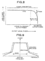
- FIG. 8 shows the relationship between output power and amplifier gain and power consumption in the ordinary transmission power amplifier such as the transmission power amplifier 13.
- the "gain" in the vertical axis of the graph of FIG. 8 represents a ratio of input power to output power of the transmission power amplifier.
- the gain is desirably constant irrespectively of the output power.
- saturated output power there is an upper limit (“saturated output power”) of the output power from the transmission power amplifier. Due to this, as shown in FIG. 8 , even if the input power of the transmission power amplifier is increased, the increase in the output power peaks near the saturated output power. In this case, an amplifier strain is generated, resulting in quality degradation of the transmission signal. To suppress such a quality degradation of the transmission signal, it is necessary to set back-off between the saturated output signal and the upper limit to the output power which can allow an amplifier strain.
- Power consumption P_dc of the transmission power amplifier 13 (13-1 to 13-N) is expressed by the following Equation (1) if the output power from the transmission power amplifier 13 is P_out.
- P_dc P_sat / ⁇ _max
- P_sat indicates the saturated output power and ⁇ _max indicates maximum efficiency decided by a configuration of the amplifier 13. If the maximum efficiency ⁇ _max is fixed, the power consumption P_dc of the transmission power amplifier 13 depends on the saturated power of the amplifier 13 and does not depend on the back-off. As shown in FIG. 8 , the power consumption is constant without dependence on the back-off.
- the degree of the nonlinear strain of the signal generated in the transmission power amplifier 13 depends on the back-off. Specifically, if the back-off is larger, the degree of the nonlinear strain is higher and modulation accuracy is higher. If the transmission rate is to be increased by increasing a modulation level to, for example, BPSK -> QPSK -> 16QAM -> 64QAM, the back-off for satisfying the modulation accuracy is increased in order of BPSK -> QPSK -> 16QAM - > 64QAM.
- required modulation accuracies are -5 dB, -8 dB, -10 dB, -13 dB, -16 dB, -19 dB, -22 dB, and -25 dB for transmission rate modes of 6 Mbps (BPSK coding rate 1/2), 9 Mbps (BPSK coding rate 3/4), 12 Mbps (QPSK coding rate 1/2), 18 Mbps (QPSK coding rate 3/4), 24 Mbps (16QAM coding rate 1/2), 36 Mbps (16QAM coding rate 3/4), 48 Mbps (64QAM coding rate 2/3), and 54 Mbps (64QAM coding rate 3/4) per 20-MHz band, respectively.
- 6 Mbps BPSK coding rate 1/2
- 9 BPSK coding rate 3/4 BPSK coding rate 3/4
- 12 Mbps QPSK coding rate 1/2
- 18 Mbps QPSK coding rate 3/4
- 48 Mbps 64QAM coding rate 2/3
- the saturated output power (P_sat) is higher, a physical size of the transmission power amplifier 13 (13-1 to 13-N) and a thermal tolerance cost in response to an increase in power consumption increase.
- a method of reducing the back-off while satisfying the required modulation accuracy so as to cut off cost is disclosed in, for example, Japanese Patent Application National Publication (Laid-Open) No. 2005-534268 to be described later.
- the Japanese Patent Application National Publication (Laid-Open) No. 2005-534268 discloses a method of processing an input signal to an amplifier in advance so as to prevent a high input signal from being input to the amplifier.
- the transmitter is configured to satisfy specifications for the wireless transmission system provided to correspond to different frequency bands, respectively.
- the specifications include specifications related to spectral mask (also known as "transmission mask”) such as a central frequency, a frequency band, and a channel leakage power, as well as maximum transmission power and modulation strain specifications.
- FIG. 9 shows transmission spectrums of an ordinary transmitter including a plurality of antennas.
- a solid line indicates the transmission spectrum of the transmitter and a broken line indicates a specified transmission spectrum.
- a signal (indicated by the solid line) transmitted from each antenna of the transmitter satisfies the spectrum specification (indicated by the broken line).
- a maximum transmission power Tx_max_Pow of the transmitter including a plurality of antennas is defined by the following Expression (2) if the number of transmission antennas used by the transmitter is N and an average transmission power per antenna is Tx_pow. N ⁇ Tx_Pow ⁇ Tx_max_Pow
- Transmission power amplifiers having equivalent performances are arranged to correspond to a plurality of antennas in the transmitter including the antennas because of easy installment of the amplifiers in a plurality of antenna-related systems, respectively. Whichever antenna-related system is selected, the corresponding transmission power amplifier operates so that a signal transmitted from the selected antenna-related system satisfies the transmission specifications.
- Equation (3) signifies that it is necessary to change the average transmission power Tx_Pow per antenna according to the number N of antennas used in communication so that the transmitter including a plurality of antennas satisfies the specifications of transmission power. It is to be noted that reduction in the average transmission power (Tx_Pow) per antenna is equivalent to setting of the back-off large in FIG. 8 .
- Table-1 shows the relationship between the number N of antennas used by the transmitter and the average transmission power Tx_Pow of the respective antennas.
- N 10
- it is necessary to increase the average transmission power Tx_Pow by 10 dB from the average transmission power Tx_Pow of one antenna (N 1), i.e., increase the back-off by 10 dB per antenna.
- Tx_Pow 10 Transmission power of each antenna-related system Tx_Pow
- Tx_max_Pow -0.0 1 Tx_max_Pow -0.0 2 Tx_max_Pow -3.0 3
- the transmission power amplifiers equivalent in performance are connected to the antennas, respectively.
- the corresponding transmission power amplifier operates according to the setting of the back-off to be able to ensure the modulation accuracy corresponding to the highest modulation level. Due to this, if a plurality of antennas is used for transmission, it is necessary to forcibly increase the back-off in light of the maximum transmission power (Tx_max_Pow).
- the modulation strain of the transmission power amplifier is reduced and the modulation accuracy is improved.
- factors deciding the modulation accuracy include not only the back-off but also fixed deterioration such as the phase noise of the oscillator. Due to this, even if the back-off is increased to reduce phase strain, the fixed deterioration such as the phase deterioration hampers the improvement in the modulation accuracy. This matter means consumption of an installation area of the transmission power amplifiers and consumption of power, which eventually prevents downsizing of the transmitter and the long service life of a battery.
- the present invention has been made to solve the conventional problems. It is an object of the present invention to provide a technique for a transmitter including a plurality of antennas capable of reducing power consumption while satisfying modulation accuracy necessary for communication.
- a transmitter comprising: a signal generation unit generating transmission signals by performing a signal processing, including coding and modulation, on data to be transmitted; a plurality of amplifiers amplifying the transmission signals by amplification characteristics having different saturated output powers, respectively; a plurality of antennas outputting the transmission signals amplified by the plurality of amplifiers, respectively; a switch connecting the plurality of amplifiers and the plurality of antennas in pairs; and a transmission control unit performing a test to determine antennas which are possible to output transmission signals each satisfying a predetermined reception quality from among the plurality of antennas, recognizing candidates of amplifiers connected to the antennas determined by the test, and selecting a specified number of amplifiers from among the candidates, wherein the transmission control unit sets higher ranks to candidates having the amplification characteristics of lower saturated output powers, applies the candidates given the higher ranks to the specified number of amplifiers, and performs a transmission processing using the specified number of amplifiers and the antennas connected to the specified number of amplifiers, respectively.
- a transmission method comprising: performing a test to determine antennas which are possible to output transmission signals each satisfying a predetermined reception quality out of a plurality of antennas; recognizing candidates of amplifiers connected to the antennas determined by the test from among a plurality of amplifiers amplifying transmission signals by amplification characteristics having different saturated output powers, respectively; setting higher ranks to candidates having amplification characteristic of lower saturated output powers, and selecting a specified number of amplifiers from among the candidates given the higher ranks; generating transmission signals by performing a signal processing, including coding and modulation, on data to be transmitted; and performing a transmission processing on the generated transmission signals using the selected specified number of amplifiers and the antennas connected to the specified number of amplifiers, respectively.
- the present invention it is possible to select amplifiers in view of the relationship between a communication quality and power consumption for a transmission processing performed by the transmitter. It is thereby possible to reduce the power consumption while satisfying the quality necessary for the communication.
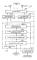
- FIG. 1 shows a configuration of a transmitter 50 according to an embodiment of the present invention.
- a signal generation unit 510 generates a transmission signal from data to be transmitted ("SOURCE INFORMATION DATA").
- N units of transmission power amplifiers 506-1 to 506-N amplify the transmission signal using different amplification characteristics, respectively.
- N units of antennas 507-1 to 507-N radiate the amplified transmission signals into the air, respectively.
- a route switch 508 connects a pair of one of the transmission power amplifiers 506-1 to 506-N and one of the antennas 507-1 to 507-N. Operations performed by these constituent elements of the transmitter 50 are controlled by a transmission control unit 500.
- the signal generation unit 510 is configured to include a coding processing unit 501, a modulation processing unit 502, a digital-analog conversion processing unit 503, and an analog signal processing unit 504.
- the coding processing unit 501 carries the source information data out a coding processing based on information of a coding rate supplied from the transmission control unit 500 and antenna information on the antennas.
- the modulation processing unit 502 performs a multilevel modulation processing, such as BPSK, QPSK, 16QAM and 64 QAM, based on information of a modulation level and the antenna information supplied from the transmission control unit 500.
- the digital-analog conversion processing unit 503 converts the digital signal from the modulation processing unit 502 into an analog signal according to the antenna information supplied from the transmission control unit 500.
- the analog signal processing unit 504 performs a predetermined signal processing on the analog signal from the digital-analog conversion processing unit 503 according to the antenna information supplied from the transmission control unit 500 and outputs the processed analog signal as a transmission signal.
- the transmission power amplifiers 506-1 to 506-N amplify the transmission signal from the signal generation unit 510 based on the antenna information supplied from the transmission control unit 500, respectively.
- the antennas 507-1 to 507-N radiate outputs from the transmission power amplifiers 506-1 to 506-N connected thereto by the route switch 508 into the air as wireless signals, respectively.
- the route switch 508 connects the transmission power amplifiers 506-1 to 506-N and the antennas 507-1 to 507-N in pairs using route switching information supplied from the transmission control unit 500.
- some of the antennas 507-1 to 507-N that are not used for the transmission processing are not connected to the corresponding amplifiers 506-1 to 506-N for saving of the power consumption.
- Amplification characteristics of the transmission power amplifiers 506-1 to 506-N included in the transmitter 50 configured as stated above will be described.
- a back-off value set to each of the transmission power amplifiers 506-1 to 506-N is defined as Bo.
- the Bo is a back-off value satisfying specifications of modulation accuracy if the number of transmission antennas is four.
- four transmission power amplifiers to 4 to which different saturated output powers P_sat(1) to P_sat(4) are set, respectively are prepared.
- the saturated output powers P_sat(1) to P_sat(4) are expressed by the following Equations (4) to (7), respectively.
- Saturated output power 1 P_sat 1 dB
- P_sat 2 P_sat 1 - 3.0 dB
- P_sat 4 P_sat 1 - 6.0 dB
- FIG. 2 shows characteristics indicated by the Expressions (8) to (11).
- a total power consumption Total_Pdc of the four transmission power amplifiers 1 to 4 having the characteristics expressed by the Expressions (8) to (11), respectively is expressed by the following Equation (12) if a true value of the saturated output power P_sat(1) is p_sat.
- a method of deciding an optimum antenna-related system from among those including the transmission power amplifiers 506-1 to 506-N and the antennas 507-1 to 507-N from viewpoints of high communication quality and low power consumption will be described.
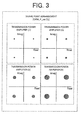
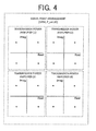
- Figs. 3 and 4 show signal point distributions of transmission signals if the four transmission power amplifiers 1 to 4 are used.
- the modulation scheme is QPSK and a magnitude of a signal point circle indicates a magnitude of errors of imaginary signal points relative to real signal points.
- FIG. 3 shows the signal point distribution if the output power from each of the four transmission power amplifiers 1 to 4 is P_sat(1) shown in FIG. 2 .
- FIG. 4 shows the signal point distribution if the output power from each of the four transmission power amplifiers 1 to 4 is P_sat(4) shown in FIG. 2 .
- the transmission power P_sat(1) is higher than P_sat(4) and that the total number of antennas used for the transmission processing is one.
- the errors in signal points are greater if the maximum transmission powers of the transmission power amplifiers 1 to 4 are lower, that is, in order of the amplifiers 1, 2, 3, and 4. This means that the modulation accuracy is deteriorated and the communication quality is degraded if the maximum transmission power is reduced.
- the power consumption is reduced in order of the transmission power amplifiers 4, 3, 2, and 1. If the power consumption is lower, battery duration is advantageously longer. In other words, the power consumption and the communication quality hold a tradeoff relationship. Therefore, an optimum transmission power amplifier is selected based on a reception quality of a receiver with which the transmitter communicates.
- P_sat(4) is selected as the output power, P_sat(4) is lower than P_sat(1), so that signals can be transmitted simultaneously from all of the four antennas.
- all the transmission power amplifiers 1 to 4 can ensure sufficient linearity in the amplification characteristics. Due to this, signal point errors are small and sufficiently high modulation accuracy can be obtained.
- Transmission power amplifier 1 (maximum power consumption-highest transmission quality) Transmission power amplifier 2 Transmission power amplifier 3
- Transmission power amplifier 4 (minimum power consumption-lowest transmission quality) 1 1 ⁇ - - - 2 1 - ⁇ - - 3 1 - - ⁇ - 4 1 - - - ⁇ 5 2 ⁇ ⁇ - - 6 2 ⁇ - ⁇ - 7 2 ⁇ - - ⁇ 8 2 - ⁇ ⁇ - 9 2 - ⁇ - ⁇ 10 2 - - ⁇ ⁇ 11 3 ⁇ ⁇ ⁇ - 12 3 ⁇ ⁇ - ⁇ 13 3 ⁇ - ⁇ ⁇ 14 3 - ⁇ ⁇ ⁇ 15 4 ⁇ ⁇ ⁇ ⁇ ⁇ ⁇
- a candidate No. "1" using the transmission power amplifier 1 shows the maximum power consumption and the highest transmission quality
- a candidate No. "4" using the transmission power amplifier 4 shows the minimum power consumption and the lowest transmission quality.
- a candidate No. "5" using the transmission power amplifiers 1 and 2 shows the maximum power consumption and the highest transmission quality
- a candidate No. "10” using the transmission power amplifiers 3 and 4 shows the minimum power consumption and the lowest transmission quality.
- a candidate No. "11” using the transmission power amplifiers 1, 2, and 3 shows the maximum power consumption and the highest transmission quality
- a candidate No. "14” using the transmission power amplifiers 2, 3 and 4 shows the minimum power consumption and the lowest transmission quality.
- the transmission control unit 500 selects an optimum transmission power amplifier for the transmission processing to be performed with a right balance between the power consumption and the communication quality. For such the selection, the transmission control unit 500 carries out a test to determine antennas which are possible to output a transmission signal satisfying a predetermined reception quality out of the antennas 507-1 to 507-N. The transmission control unit 500 recognizes amplifiers connected to the determined antennas as candidates, and selects a specified number of amplifiers from among the candidates.
- the transmission control unit 500 determines whether a power saving mode is selected by a user's operation or the like before starting a transmission processing in response to the data transmission request (step S1).
- the transmission control unit 500 transmits test packets for testing whether at what qualities a receiver receives the signals transmitted from the respective antennas of the transmitter 50 to the receiver (step S2).
- the test packets are transmitted by using all the transmission power amplifiers 506-1 to 506-N and the antennas 507-1 to 507-N of the transmitter 50.
- the receiver that receives the test packets transmits information on quality of reception of the test packets (hereinafter "reception quality information") to the transmitter 50.
- the reception quality information includes information on communication path and rate of successful reception.
- the transmission control unit 500 acquires the reception quality information mentioned above (step S3), it selects some of the transmission power amplifiers 506-1 to 506-N as many as the number of antennas for the current transmission processing, and decides to use the selected amplifiers for the transmission processing (step S4). At this time, the transmission control unit 500 can perform an averaging processing related to the communication quality to improve quality estimation accuracy if necessary.
- the transmission control unit 500 starts the transmission processing using the selected transmission power amplifiers and the antennas connected to the selected transmission power amplifiers (step S5).
- CINRs Carrier to Interference plus Noise Ratios
- the transmission control unit 500 compares each of four reception CINRs (CINR1, CINR2, CINR3, and CINR4) acquired by the four antennas 1 to 4 with a threshold CINR (Th_CINR) preset as a determination threshold value (step S11).
- the threshold CINR is not limited to a fixed value but can be changed according to a coding rate, a modulation level, a transmission band or the like applied to the signal generation unit 510.
- step S12: Yes the transmission control unit 500 recognizes that the transmission power amplifier corresponding to the reception CINR is effective to satisfy a communication quality standard. Then the transmission control unit 500 recognizes the transmission power amplifier as a candidate (step S13). If the reception CINR is equal to or lower than the threshold CINR (step S12: No), the transmission control unit 500 does not select the transmission power amplifier corresponding to the reception CINR as a candidate.
- some transmission power amplifiers which bring an optimum quality of communication are sorted from the transmission power amplifiers 506-1 to 506-N.
- the transmission control unit 500 sets ranks of the transmission power amplifiers 1, 2, and 4 selected as candidates in view of their power consumptions (step S15).
- the transmission control unit 500 sets a higher rank to the transmission power amplifier whose consumption power is lower, that is, whose P_sat (the saturated output power) is lower.
- the transmission power amplifier 4 is given the highest rank
- the transmission power amplifier 2 is given the second highest rank
- the transmission power amplifier 1 is given the lowest rank according to the characteristics shown in FIG. 2 .
- the transmission control unit 500 selects amplifiers as many as the number of antennas for the current transmission processing (step S16). If the number of antennas is preset as one, the transmission power amplifier 4 is selected. Because the transmission power amplifier 4 is given the highest rank. Then the transmission power amplifier 4 and the antenna 4 connected to the transmission power amplifier 4 are used for the transmission processing.
- the transmission power amplifier 4 given the highest rank and the transmission power amplifier 2 given the second highest rank are selected. Then a combination of the transmission power amplifier 4 and the antenna 4, and that of the transmission power amplifier 2 and the antenna 2 are used for the transmission processing.
- the transmission control unit 500 exerts control to select amplifier candidates using the reception quality information and to preferentially adopt candidates lower in power consumption for the transmission processing from among those candidates. It is thereby possible to select optimum amplifiers for the transmission processing in view of a balance between the communication quality and the power consumption.
- the CINRs are used as the reception quality information, it is possible to use other information as one.
- the test packet is transmitted to test the reception quality of the transmission signal, another test method can be adopted. For example, a test method including calculating the rate of successful reception as to each antenna using information on notifying success in reception of data packets (ACK), information on notifying failure in reception of data packets (NACK) or the like, and comparing the probability with a determination threshold.
- ACK notifying success in reception of data packets
- NACK notifying failure in reception of data packets
- the combination of pairs of the transmission power amplifiers 506-1 to 506-N and the antennas 507-1 to 507-N is assumed to be fixed.
- the combination is not limited to the fixed one but can be changed if necessary.
- some of the antennas to be used for the transmission processing are decided when starting the transmission processing, and are changed connections with amplifiers by the route switch 508 according to the selection of amplifiers. Such control is effective if the antennas of the transmitter 50 differ in their arrangement and radiation directions of radio wave.
- the route switch 508 connects the amplifier 1 to the antenna 1, and connects the amplifier 2 to the antenna 2.
- the amplifier 1 is selected as the transmission power amplifier for the transmission processing.
- the Table-3 there are two pairs as to the selected amplifier 1. Those are, a combination of the amplifier 1 and the antenna 1 as the initial setting, and the other combination of the amplifier 1 and the antenna 2. If the antenna 2 has been decided as the antenna used for the transmission processing since the beginning of that processing, the transmission control unit 500 controls the route switch 508 to connect the selected amplifier 1 with the antenna 2 instead of the antenna 1 as the initial setting.
- the transmission control unit 500 can make the above-stated determination using, for example, the reception quality information.
- the transmission control unit 500 acquires and records reception quality information per combination of the amplifier and the antenna. If the transmission control unit 500 recognizes degradation in the communication quality from the reception quality information for the current combination, the transmission control unit 500 instructs the route switch 508 to switch over antennas. Alternatively, if the acquired reception quality information slightly differs from the determination threshold, the transmission control unit 500 can instructs the route switch 508 to switch over antennas.
- An example 1 describes a transmitter comprising: a signal generation unit generating transmission signals by performing a signal processing, including coding and modulation, on data to be transmitted; a plurality of amplifiers amplifying the transmission signals by amplification characteristics having different saturated output powers, respectively; a plurality of antennas outputting the transmission signals amplified by the plurality of amplifiers, respectively; a switch connecting the plurality of amplifiers and the plurality of antennas in pairs; and a transmission control unit performing a test to determine antennas which are possible to output transmission signals each satisfying a predetermined reception quality from among the plurality of antennas, recognizing candidates of amplifiers connected to the antennas determined by the test, and selecting a specified number of amplifiers from among the candidates, wherein the transmission control unit sets higher ranks to candidates having the amplification characteristics of lower saturated output powers, applies the candidates given the higher ranks to the specified number of amplifiers, and performs a transmission processing using the specified number of amplifiers and the antennas connected to the specified number of amplifiers, respectively.
- An example 2 describes the transmitter according to the example 1, wherein the plurality of antennas is arranged so as to differ in radiation direction of radio wave, and the transmission control unit selects the antennas to be connected to the specified number of amplifiers based on the arrangement from among the plurality of antennas, and controls the switch to connect the selected antennas to the specified number of amplifiers, respectively.
- An example 3 describes the transmitter according to the example 1 or 2, wherein when the test is performed, the transmission control unit acquires reception quality information indicating a reception quality of each of the transmission signals output from the plurality of antennas from a receiver, and makes the determination of the antennas based on the reception quality information on each of the plurality of antennas.
- An example 4 describes the transmitter according to the example 3, wherein the transmission control unit acquires CINR (Carrier to Interference plus Noise Ratio) as the reception quality information.
- CINR Carrier to Interference plus Noise Ratio
- An example 5 describes the transmitter according to any one of the examples 1 to 4, wherein the transmission control unit changes a threshold value for the determination of the antennas in the test according to coding rate and modulation type applied to the signal generation unit.
- An example 6 describes a transmission method comprising: performing a test to determine antennas which are possible to output transmission signals each satisfying a predetermined reception quality out of a plurality of antennas; recognizing candidates of amplifiers connected to the antennas determined by the test from among a plurality of amplifiers amplifying transmission signals by amplification characteristics having different saturated output powers, respectively; setting higher ranks to candidates having amplification characteristic of lower saturated output powers, and selecting a specified number of amplifiers from among the candidates given the higher ranks; generating transmission signals by performing a signal processing, including coding and modulation, on data to be transmitted; and performing a transmission processing on the generated transmission signals using the selected specified number of amplifiers and the antennas connected to the specified number of amplifiers, respectively.
- An example 7 describes the transmission method according to the example 6, further comprising steps of arranging the plurality of antennas so as to differ in radiation direction of radio wave, and selecting the antennas to be connected to the specified number of amplifiers based on the arrangement of the plurality of antennas.
- An example 8 describes the transmission method according to the example 6 or 7, wherein the test includes steps of acquiring reception quality information indicating a reception quality of each of the transmission signals output from the plurality of antennas from a receiver, and making the determination of the antennas based on the reception quality information on each of the plurality of antennas.
- An example 9 describes the transmission method according to the example 8, wherein the reception quality information to be acquired from the receiver is CINR (Carrier to Interference plus Noise Ratio).
- An example 10 describes the transmission method according to any one of the examples 6 to 9, wherein the test includes step of changing a threshold value for the determination of the antennas according to coding rate and modulation type applied to the signal processing.
- a transmitter performs a test to determine antennas which are possible to output transmission signals each satisfying a predetermined reception quality out of among a plurality of antennas.
- the transmitter recognizes candidates of amplifiers connected to the antennas determined by the test from among a plurality of amplifiers amplifying transmission signals by amplification characteristics having different saturated output powers, respectively.
- the transmitter sets higher ranks to candidates having amplification characteristic of lower saturated output powers, and selects a specified number of amplifiers from among the candidates given the higher ranks.
- the transmitter performs a transmission processing on the transmission signals using the selected specified number of amplifiers and the antennas connected to the specified number of amplifiers, respectively.
Landscapes
- Engineering & Computer Science (AREA)
- Computer Networks & Wireless Communication (AREA)
- Signal Processing (AREA)
- Transmitters (AREA)
- Monitoring And Testing Of Transmission In General (AREA)
Applications Claiming Priority (1)
| Application Number | Priority Date | Filing Date | Title |
|---|---|---|---|
| JP2007176210A JP2009017193A (ja) | 2007-07-04 | 2007-07-04 | 送信機および送信方法 |
Publications (2)
| Publication Number | Publication Date |
|---|---|
| EP2012444A2 true EP2012444A2 (de) | 2009-01-07 |
| EP2012444A3 EP2012444A3 (de) | 2009-05-13 |
Family
ID=39797037
Family Applications (1)
| Application Number | Title | Priority Date | Filing Date |
|---|---|---|---|
| EP08158300A Withdrawn EP2012444A3 (de) | 2007-07-04 | 2008-06-16 | Sender und Übertragungsverfahren |
Country Status (5)
| Country | Link |
|---|---|
| US (1) | US20090011787A1 (de) |
| EP (1) | EP2012444A3 (de) |
| JP (1) | JP2009017193A (de) |
| CN (1) | CN101340226A (de) |
| TW (1) | TW200919997A (de) |
Cited By (1)
| Publication number | Priority date | Publication date | Assignee | Title |
|---|---|---|---|---|
| WO2013087508A1 (fr) * | 2011-12-13 | 2013-06-20 | Thomson Licensing | Terminal de communication mimo avec controle de puissance |
Families Citing this family (47)
| Publication number | Priority date | Publication date | Assignee | Title |
|---|---|---|---|---|
| US8854019B1 (en) | 2008-09-25 | 2014-10-07 | Rf Micro Devices, Inc. | Hybrid DC/DC power converter with charge-pump and buck converter |
| JP2010176330A (ja) | 2009-01-28 | 2010-08-12 | Sony Corp | 情報処理装置、及び表示制御方法 |
| US9166471B1 (en) | 2009-03-13 | 2015-10-20 | Rf Micro Devices, Inc. | 3D frequency dithering for DC-to-DC converters used in multi-mode cellular transmitters |
| JP5023170B2 (ja) * | 2009-04-27 | 2012-09-12 | 株式会社エヌ・ティ・ティ・ドコモ | ユーザ装置、基地局装置及び通信制御方法 |
| JP2012124967A (ja) * | 2009-04-27 | 2012-06-28 | Ntt Docomo Inc | ユーザ装置、基地局装置及び通信制御方法 |
| US8315576B2 (en) | 2009-05-05 | 2012-11-20 | Rf Micro Devices, Inc. | Capacitive compensation of cascaded directional couplers |
| JP5500894B2 (ja) * | 2009-07-22 | 2014-05-21 | シャープ株式会社 | 端末装置および通信方法 |
| US8548398B2 (en) * | 2010-02-01 | 2013-10-01 | Rf Micro Devices, Inc. | Envelope power supply calibration of a multi-mode radio frequency power amplifier |
| US8538355B2 (en) | 2010-04-19 | 2013-09-17 | Rf Micro Devices, Inc. | Quadrature power amplifier architecture |
| US9048787B2 (en) | 2010-04-20 | 2015-06-02 | Rf Micro Devices, Inc. | Combined RF detector and RF attenuator with concurrent outputs |
| US9008597B2 (en) | 2010-04-20 | 2015-04-14 | Rf Micro Devices, Inc. | Direct current (DC)-DC converter having a multi-stage output filter |
| US8842399B2 (en) | 2010-04-20 | 2014-09-23 | Rf Micro Devices, Inc. | ESD protection of an RF PA semiconductor die using a PA controller semiconductor die |
| US9077405B2 (en) | 2010-04-20 | 2015-07-07 | Rf Micro Devices, Inc. | High efficiency path based power amplifier circuitry |
| US8699973B2 (en) | 2010-04-20 | 2014-04-15 | Rf Micro Devices, Inc. | PA bias power supply efficiency optimization |
| US8983410B2 (en) | 2010-04-20 | 2015-03-17 | Rf Micro Devices, Inc. | Configurable 2-wire/3-wire serial communications interface |
| US9900204B2 (en) | 2010-04-20 | 2018-02-20 | Qorvo Us, Inc. | Multiple functional equivalence digital communications interface |
| US8989685B2 (en) | 2010-04-20 | 2015-03-24 | Rf Micro Devices, Inc. | Look-up table based configuration of multi-mode multi-band radio frequency power amplifier circuitry |
| US8731498B2 (en) | 2010-04-20 | 2014-05-20 | Rf Micro Devices, Inc. | Temperature correcting an envelope power supply signal for RF PA circuitry |
| US8892063B2 (en) | 2010-04-20 | 2014-11-18 | Rf Micro Devices, Inc. | Linear mode and non-linear mode quadrature PA circuitry |
| US8706063B2 (en) | 2010-04-20 | 2014-04-22 | Rf Micro Devices, Inc. | PA envelope power supply undershoot compensation |
| US9362825B2 (en) | 2010-04-20 | 2016-06-07 | Rf Micro Devices, Inc. | Look-up table based configuration of a DC-DC converter |
| US9577590B2 (en) | 2010-04-20 | 2017-02-21 | Qorvo Us, Inc. | Dual inductive element charge pump buck and buck power supplies |
| US9214900B2 (en) | 2010-04-20 | 2015-12-15 | Rf Micro Devices, Inc. | Interference reduction between RF communications bands |
| US8913971B2 (en) | 2010-04-20 | 2014-12-16 | Rf Micro Devices, Inc. | Selecting PA bias levels of RF PA circuitry during a multislot burst |
| US9553550B2 (en) | 2010-04-20 | 2017-01-24 | Qorvo Us, Inc. | Multiband RF switch ground isolation |
| US8942651B2 (en) | 2010-04-20 | 2015-01-27 | Rf Micro Devices, Inc. | Cascaded converged power amplifier |
| US8913967B2 (en) | 2010-04-20 | 2014-12-16 | Rf Micro Devices, Inc. | Feedback based buck timing of a direct current (DC)-DC converter |
| US8831544B2 (en) | 2010-04-20 | 2014-09-09 | Rf Micro Devices, Inc. | Dynamic device switching (DDS) of an in-phase RF PA stage and a quadrature-phase RF PA stage |
| US8712349B2 (en) | 2010-04-20 | 2014-04-29 | Rf Micro Devices, Inc. | Selecting a converter operating mode of a PA envelope power supply |
| US8942650B2 (en) | 2010-04-20 | 2015-01-27 | Rf Micro Devices, Inc. | RF PA linearity requirements based converter operating mode selection |
| US8958763B2 (en) | 2010-04-20 | 2015-02-17 | Rf Micro Devices, Inc. | PA bias power supply undershoot compensation |
| US9030256B2 (en) | 2010-04-20 | 2015-05-12 | Rf Micro Devices, Inc. | Overlay class F choke |
| US8811920B2 (en) | 2010-04-20 | 2014-08-19 | Rf Micro Devices, Inc. | DC-DC converter semiconductor die structure |
| US9214865B2 (en) | 2010-04-20 | 2015-12-15 | Rf Micro Devices, Inc. | Voltage compatible charge pump buck and buck power supplies |
| US8983407B2 (en) | 2010-04-20 | 2015-03-17 | Rf Micro Devices, Inc. | Selectable PA bias temperature compensation circuitry |
| US8947157B2 (en) | 2010-04-20 | 2015-02-03 | Rf Micro Devices, Inc. | Voltage multiplier charge pump buck |
| US8811921B2 (en) | 2010-04-20 | 2014-08-19 | Rf Micro Devices, Inc. | Independent PA biasing of a driver stage and a final stage |
| US9184701B2 (en) | 2010-04-20 | 2015-11-10 | Rf Micro Devices, Inc. | Snubber for a direct current (DC)-DC converter |
| CN102377463B (zh) * | 2010-08-09 | 2014-12-31 | 中兴通讯股份有限公司 | 多用户多入多出系统中的配对方法、数据传输方法及装置 |
| KR101919885B1 (ko) * | 2012-01-03 | 2018-11-19 | 엘지전자 주식회사 | 이동 단말기 |
| US9065505B2 (en) | 2012-01-31 | 2015-06-23 | Rf Micro Devices, Inc. | Optimal switching frequency for envelope tracking power supply |
| CN104052505B (zh) * | 2013-11-07 | 2016-04-13 | 无锡泽太微电子有限公司 | 单芯片无线发射机、发射芯片及信号发射方法 |
| CN106575986B (zh) * | 2014-08-13 | 2021-02-12 | 诺基亚通信公司 | 调节用于基于特征值的波束形成的传输功率的方法 |
| KR102516621B1 (ko) | 2016-04-08 | 2023-03-31 | 삼성전자주식회사 | 안테나를 제어하기 위한 방법 및 그 전자 장치 |
| US10211904B2 (en) * | 2016-04-19 | 2019-02-19 | Telefonaktiebolaget Lm Ericsson (Publ) | Power control and beamforming with a plurality of power amplifiers |
| CN110084712A (zh) * | 2016-10-26 | 2019-08-02 | 奥康科技有限公司 | 用于分析图像和提供反馈的可佩戴设备和方法 |
| CN113541755B (zh) * | 2020-04-17 | 2023-06-16 | 华为技术有限公司 | 天线选择方法及相关设备 |
Citations (1)
| Publication number | Priority date | Publication date | Assignee | Title |
|---|---|---|---|---|
| JP2007176210A (ja) | 2005-12-27 | 2007-07-12 | Auto Network Gijutsu Kenkyusho:Kk | 車両用電源制御装置 |
Family Cites Families (2)
| Publication number | Priority date | Publication date | Assignee | Title |
|---|---|---|---|---|
| KR100706634B1 (ko) * | 2004-11-12 | 2007-04-11 | 한국전자통신연구원 | 성능이 향상된 다중 안테나 시스템 |
| US20080212538A1 (en) * | 2005-07-15 | 2008-09-04 | Molisch Andreas F | Antenna Selection For Multi-Input Multi-Output System |
-
2007
- 2007-07-04 JP JP2007176210A patent/JP2009017193A/ja not_active Withdrawn
-
2008
- 2008-06-11 TW TW097121691A patent/TW200919997A/zh unknown
- 2008-06-16 EP EP08158300A patent/EP2012444A3/de not_active Withdrawn
- 2008-06-24 US US12/145,192 patent/US20090011787A1/en not_active Abandoned
- 2008-07-02 CN CNA2008101295739A patent/CN101340226A/zh active Pending
Patent Citations (1)
| Publication number | Priority date | Publication date | Assignee | Title |
|---|---|---|---|---|
| JP2007176210A (ja) | 2005-12-27 | 2007-07-12 | Auto Network Gijutsu Kenkyusho:Kk | 車両用電源制御装置 |
Cited By (1)
| Publication number | Priority date | Publication date | Assignee | Title |
|---|---|---|---|---|
| WO2013087508A1 (fr) * | 2011-12-13 | 2013-06-20 | Thomson Licensing | Terminal de communication mimo avec controle de puissance |
Also Published As
| Publication number | Publication date |
|---|---|
| US20090011787A1 (en) | 2009-01-08 |
| CN101340226A (zh) | 2009-01-07 |
| EP2012444A3 (de) | 2009-05-13 |
| TW200919997A (en) | 2009-05-01 |
| JP2009017193A (ja) | 2009-01-22 |
Similar Documents
| Publication | Publication Date | Title |
|---|---|---|
| EP2012444A2 (de) | Sender und Übertragungsverfahren | |
| KR101517170B1 (ko) | 다중 안테나 시스템에서 전력 소모를 줄이기 위한 장치 및 방법 | |
| CN101569113B (zh) | 利用发射分集的wcdma功率节省 | |
| US6393276B1 (en) | Mobile station assisted forward link open loop power and rate control in a CDMA system | |
| US6968201B1 (en) | Method and apparatus for controlling reverse link interference rise and power control instability in a wireless system | |
| US7209703B1 (en) | Wireless repeater with intelligent signal display | |
| US8588696B2 (en) | Adaptive cellular power control | |
| US8358615B2 (en) | Modulation and coding scheme selection method for a specific absorption rate compliant communication device | |
| US20100062799A1 (en) | Mobile communication system, base station, mobile station, and communication control method | |
| EP1576743B1 (de) | Geschaltete antennen-sende-diversität | |
| US7499681B2 (en) | Apparatus, system, and method for managing an antenna network during a half duplex call | |
| US20170019279A1 (en) | Wireless communication apparatus | |
| US8285220B2 (en) | Method and apparatus for reducing a channel deviation in a mobile communication terminal | |
| US8538474B2 (en) | Method and apparatus of adjusting transmission power | |
| US6738605B1 (en) | Method for optimizing an operating point of a power amplifier in a WCDMA mobile terminal | |
| US7379747B2 (en) | Method for controlling output power of handheld terminal in mobile communication system | |
| US6760604B2 (en) | Portable radio transceiver having shared power source for audio and RF amplifiers | |
| JP2008011329A (ja) | 携帯通信機およびアンテナ制御方法 | |
| WO2007065478A1 (en) | Wireless subscriber communication unit and method of power control with back-off therefore | |
| US20070129024A1 (en) | Transmitter | |
| KR100659540B1 (ko) | 이동통신단말기에서 역방향 송신전력을 제어하기 위한장치 및 방법 | |
| CN111757332B (zh) | 一种网络覆盖优化设备及其增益控制方法 | |
| JP2003198460A (ja) | 無線アクセスシステム | |
| JP2011018966A (ja) | 移動体データ通信システムの無線基地局 | |
| JP2008167500A (ja) | 送信電力制御方法及び無線アクセスシステム |
Legal Events
| Date | Code | Title | Description |
|---|---|---|---|
| PUAI | Public reference made under article 153(3) epc to a published international application that has entered the european phase |
Free format text: ORIGINAL CODE: 0009012 |
|
| AK | Designated contracting states |
Kind code of ref document: A2 Designated state(s): AT BE BG CH CY CZ DE DK EE ES FI FR GB GR HR HU IE IS IT LI LT LU LV MC MT NL NO PL PT RO SE SI SK TR |
|
| AX | Request for extension of the european patent |
Extension state: AL BA MK RS |
|
| PUAL | Search report despatched |
Free format text: ORIGINAL CODE: 0009013 |
|
| AK | Designated contracting states |
Kind code of ref document: A3 Designated state(s): AT BE BG CH CY CZ DE DK EE ES FI FR GB GR HR HU IE IS IT LI LT LU LV MC MT NL NO PL PT RO SE SI SK TR |
|
| AX | Request for extension of the european patent |
Extension state: AL BA MK RS |
|
| 17P | Request for examination filed |
Effective date: 20091113 |
|
| AKX | Designation fees paid |
Designated state(s): DE FR GB IT |
|
| GRAP | Despatch of communication of intention to grant a patent |
Free format text: ORIGINAL CODE: EPIDOSNIGR1 |
|
| STAA | Information on the status of an ep patent application or granted ep patent |
Free format text: STATUS: THE APPLICATION IS DEEMED TO BE WITHDRAWN |
|
| 18D | Application deemed to be withdrawn |
Effective date: 20100904 |