EP2012464A2 - Procédés et appareil pour fournir et programmer des ressources dans un réseau de communication - Google Patents
Procédés et appareil pour fournir et programmer des ressources dans un réseau de communication Download PDFInfo
- Publication number
- EP2012464A2 EP2012464A2 EP08006540A EP08006540A EP2012464A2 EP 2012464 A2 EP2012464 A2 EP 2012464A2 EP 08006540 A EP08006540 A EP 08006540A EP 08006540 A EP08006540 A EP 08006540A EP 2012464 A2 EP2012464 A2 EP 2012464A2
- Authority
- EP
- European Patent Office
- Prior art keywords
- resource
- service
- transport
- entities
- transport networks
- Prior art date
- Legal status (The legal status is an assumption and is not a legal conclusion. Google has not performed a legal analysis and makes no representation as to the accuracy of the status listed.)
- Withdrawn
Links
Images


Classifications
-
- H—ELECTRICITY
- H04—ELECTRIC COMMUNICATION TECHNIQUE
- H04L—TRANSMISSION OF DIGITAL INFORMATION, e.g. TELEGRAPHIC COMMUNICATION
- H04L47/00—Traffic control in data switching networks
- H04L47/70—Admission control; Resource allocation
- H04L47/82—Miscellaneous aspects
- H04L47/822—Collecting or measuring resource availability data
-
- H—ELECTRICITY
- H04—ELECTRIC COMMUNICATION TECHNIQUE
- H04L—TRANSMISSION OF DIGITAL INFORMATION, e.g. TELEGRAPHIC COMMUNICATION
- H04L47/00—Traffic control in data switching networks
- H04L47/10—Flow control; Congestion control
-
- H—ELECTRICITY
- H04—ELECTRIC COMMUNICATION TECHNIQUE
- H04L—TRANSMISSION OF DIGITAL INFORMATION, e.g. TELEGRAPHIC COMMUNICATION
- H04L47/00—Traffic control in data switching networks
- H04L47/70—Admission control; Resource allocation
- H04L47/83—Admission control; Resource allocation based on usage prediction
Definitions
- the present application relates generally to the operation of data networks, and more particularly, to methods and apparatus for resource provisioning and planning in a communication network.
- the multimedia content may be distributed from the content provider to the content consumer (also known as end user) over different types of transport networks (TNs) that comprise wired and/or wireless networks.
- TNs transport networks
- a set of multimedia components (such as video and audio components) are offered as a whole to the end user and are referred to as a 'Service'.
- the logical entity in a TN that provides transport to the service component is called a 'Flow'.
- Each Service in the system may have associated Quality of Service (QoS) criteria that should be met to provide a desired quality level at a receiving device.
- QoS Quality of Service
- the QoS criteria are described in a service layer agreement between the content provider and the system operator. Configuring such a system to carry Services over different TNs to meet their desired QoS requirements can be very complicated, especially in transport networks where the resource is scarce and over-provisioning is not affordable, as in wireless networks.
- a provisioning system comprising methods and apparatus, that operates to provide resource provisioning and planning in a communication system.
- a method for resource planning in a communication network.
- the method comprises generating one or more resource entities that represent resource requirements of one or more targeted services, respectively, wherein the resource entities are modeled from at least one of transport network dependent information and transport network independent information, and determining whether the one or more resource entities can be supported by one or more transport networks.
- an apparatus for resource planning in a communication network.
- the apparatus comprises input logic configured to receive at least one of transport network dependent information and transport network independent information, and processing logic configured to generate one or more resource entities that represent resource requirements of one or more targeted services, respectively, wherein the resource entities are modeled from at least one of the transport network dependent information and the transport network independent information; and wherein said processing logic is configured to determine whether the one or more resource entities can be supported by one or more transport networks.
- an apparatus for resource planning in a communication network comprises means for generating one or more resource entities that represent resource requirements of one or more targeted services, respectively, wherein the resource entities are modeled from at least one of transport network dependent information and transport network independent information, and means for determining whether the one or more resource entities can be supported by one or more transport networks.
- a computer program product for resource planning in a communication network.
- the computer program product comprises a machine-readable medium embodying a first set of codes for causing a computer to generate one or more resource entities that represent resource requirements of one or more targeted services, respectively, wherein the resource entities are modeled from at least one of transport network dependent information and transport network independent information, and a second set of codes for causing the computer to determine whether the one or more resource entities can be supported by one or more transport networks.
- At least one integrated circuit is provided that is configured for planning in a communication network.
- the at least one integrated circuit comprises a first module for generating one or more resource entities that represent resource requirements of one or more targeted services, respectively, wherein the resource entities are modeled from at least one of transport network dependent information and transport network independent information, and a second module for determining whether the one or more resource entities can be supported by one or more transport networks.
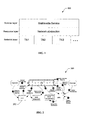
- FIG. 1 shows a diagram that illustrates how information in a communication system is divided into three layers in aspects of a provisioning system
- FIG. 2 illustrates a workflow diagram for use in aspects of a provisioning system
- FIG. 3 shows an exemplary FLO protocol stack for use in aspects of a provisioning system
- FIG. 4 shows an exemplary slot allocation for use in aspects of a provisioning system
- FIG. 5 shows an exemplary method for resource planning for use in aspects of a provisioning system
- FIG. 6 shows a diagram that illustrates a Delivery Window and a Schedule Window for use in aspects of a provisioning system
- FIG. 7 shows an exemplary method for a file delivery resource scheduling algorithm for use in aspects of a provisioning system
- FIG. 8 shows exemplary NPR logic for use in aspects of a provisioning system
- FIG. 9 shows exemplary provisioning logic for use in aspect of a provisioning system.
- a provisioning system operates to provide resource provisioning and planning in a communication network.
- the system models a variety of Service content types and uses these models to determine network resources required to provide selected QoS at a receiving device.
- the system then provides a planning result that indicates whether the desired Service content can be provisioned over a selected TN.
- the system is especially well suited for use in wireless network environments, but may be used in any type of network environment, including but not limited to, communication networks, public networks, such as the Internet, private networks, such as virtual private networks (VPN), local area networks, wide area networks, long haul networks, or any other type of data network.
- VPN virtual private networks
- a 'Resource' entity is defined as a logical entity that describes network resource usage in different TNs that can be offered to an application layer Service.
- a Resource may include one or multiple Resource Descriptors, where each descriptor describes the network resource usage for an independent media component in the Service.
- the configuration data in a Resource Descriptor can include two types of information:
- a Resource Descriptor can include one set of TN-independent QoS requirements and multiple sets of the TN-specific data, one for each TN carrying the service component.
- FIG. 1 shows a diagram 100 that illustrates how information in a communication system is divided into the following three layers in aspects of a provisioning system.
- the Resource layer provides an abstraction between the service layer and network layer in the communication system.
- the Resource layer provides the following features:
- a Service can be added to or removed from any TN without impacting the service layer configurations.
- the provisioning system provides a mechanism to plan the Resources in the TNs before offering the Resources to carry Services. During resource planning, the capacity of the TN is verified to ensure that the configured Resources can be accommodated without network resource overbooking. In an aspect, priorities are given to the Resources for resource allocation during planning. In another aspect, different modeling techniques are used for different types of Flows described by the Resource Descriptors. If the planning fails, the provisioning system provides feedbacks to a provisioning operator for adjusting the configuration of the Resources offered in the system such that the updated Resources do not exceed the network capacity.
- a mechanism for generating the delivery schedule for the Resource in the corresponding TNs, such that the QoS requirements of the Services to be carried by the Resource are met.
- the provisioning system is able to offer the Resources to carry Services.
- Another aspect provides a mechanism to associate a Service to a Resource.
- a Service can be associated with any Resource in the system, as long as the Resource can meet the QoS requirement of the Service in the target TNs.
- a Resource can be offered to carry any Service as long as the resource configuration meets the QoS requirements of the Service.
- the system is ready to deliver the content of a Service after a Resource is assigned to carry the Service.
- Another aspect provides a mechanism by which the Resource configuration, delivery schedules (either in a recurring template or absolute time), and its Service association information are delivered to the transport network components in the system. These Resource parameters are used by the transport network components to serve the Service components and to perform run-time admission control and traffic policing for the corresponding Service content.
- the Resource delivery schedule for a Service may be sent to the end user (i.e., receiving device) in advance.
- the user will be able to know when and how the Service content is delivered and start receiving the Service accordingly. This may be important in mobile networks where the device has limited power and/or processing capacity.
- a RAN comprises a Forward Link Only (FLO) network or any other suitable type of network.
- FLO Forward Link Only
- the distribution system comprises two segments described as follows.
- the provisioning system there are four fundamental types of Services supported; however, the system is not limited to these service types and is operable to support other service types or service sub-types. For example, the following services types are supported.
- the Resource entity is used in the system to provide a RAN abstraction to the MDS segment.
- a corresponding Resource entity is modeled from TN dependent and independent information to describe the QoS requirements of the targeted Service and the corresponding RAN delivery schedules and configurations.
- the Resource entity in the system includes the following parameters:
- one or more Resource Descriptors in the Resource are determined to describe the QoS requirements and RAN usage of the Flow that carries the targeted Service component.
- the following parameters are specified for each Resource Descriptor in the Resource:
- the corresponding targeted Service content includes files, the following QoS parameters are specified for each file.
- provisioning is divided into three tasks, namely: network level provision, resource level provision, and service level provision.
- Provisioning Subsystem is defined to handle provisioning related functions within the system.
- the Provisioning Subsystem comprises the following three components.
- FIG. 2 illustrates a workflow diagram 200 for use in aspects of a provisioning system.
- the workflow diagram 200 illustrates the operation of aspects of the provisioning system to provide network provisioning, network resource provisioning, and service provisioning.
- network resource planning (NRP) logic 202 operates to provide Resource provisioning as described herein.
- any update to the service layer configuration can be made at the SPS without impacting the underlying Resource configuration.
- the NRP will re-plan the Resources in the network and update the Resources transparent to the service layer configuration.
- a network resource scheduling procedure is performed by the NRP logic 202 by processing a set of candidate Resources as input and outputting a set of schedulable Resources that can be accommodated together in the system.
- the candidate resources are resource entities associated with targeted services that have been modeled from TN dependent and independent information.
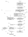
- FIG. 3 shows an exemplary method 300 for resource scheduling for use in aspects of a provisioning system.
- the method 300 is performed by the NRP logic 202.
- a list of candidate Resources i.e., resource entities
- the list of candidate Resources are generated based on targeted Services to be transported in the network.
- the list of candidate Resources is sorted in priority from high to low. For example, a candidate Resources associated with a targeted real time Service is given a higher priority than a candidate Resource associated with a targeted IP data cast service. It should be noted that the targeted Services and their associated candidate Resources may be assigned any desired priority to determine the order in which the candidate Resources are sorted.
- the method 300 is suitable for use with any set of candidate Resources derived from any suitable service types not limited to the service types described herein. A description of the method 300 is provided below and the following definitions apply.
- L IN list of candidate Resources provided as input and sorted by their assigned priorities from high to low.
- L IN_J candidate Resource J in list L IN .
- L OUT list of schedulable Resources.
- N total number of candidate Resources in L IN .
- the method starts with an empty list of schedulable Resources (L OUT ) and index J set to "1.”
- the list of candidate Resources (L IN ) are processed one by one based on their priorities from high to low. For example, a candidate Resource on top of the input Resources list (L IN ) is added to the schedulable list (L OUT ).
- the NRP logic 202 notifies the operator regarding candidate Resources that are not schedulable and provides the reasons for the failures.
- the method 300 continues at block 312 until all candidate Resources in the list (L IN ) have been tested for inclusion in the schedulable list (L OUT ).
- L OUT comprises a list of schedulable Resources.
- the method 300 is performed for candidate resources derived from targeted RT services, IPDS services, and FD services.
- the method 300 is suitable for use with other candidate resources derived from other types of services.
- the criteria used for successful scheduling of L OUT at block 306 may be different for different resource types. A description of the algorithms used for each resource type is provided in the following sections. Thus, the method 300 operates to determine the schedulable list of resources L OUT .
- a scheduling procedure is performed to determine whether the Resources in the L OUT list can be scheduled together for each network.
- B j the application layer data rate for MLC j.
- B Y i the total application layer data rate of resource type Y in network i , where Y can be Overhead (O), RT, IPDS, and FD
- D j the physical layer data rate for MLC j
- D Y i the total physical layer data rate of resource type Y in network i
- sp j the number of slots per PLP for MLC j.
- Slot Y i the total number of data slots per super-frame used by resource type Y in network i.
- S Y i the physical layer OFDM data symbols per frame used by resource type Y in network i.
- e Y the efficiency of slot allocation for resource type Y, which equals the ratio between the number of data slots per frame for resource type Y and the number of slots in S Y i .
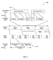
- FIG. 4 shows an exemplary FLO protocol stack 400 for use in aspects of a provisioning system.
- the resource definitions describe the QoS requirement (e.g., data rate) at the application layer for each service component.
- each service component is carried in an individual flow.
- One or more flows are carried by a Media Logical Channel (MLC) in the FLO RAN. While being transmitted over the FLO air interface, the following FLO protocol stack overhead is added to the flow.
- MLC Media Logical Channel
- application layer 402 data traffic B j belonging to a flow is broken into multiple 121 bytes (968 bits) fragments at the transport layer.
- a one-byte Framing Header (FH) is added to each fragment to form a 122 byte stream layer block. If necessary, padding is added to the last block to make each block exactly 122 bytes.
- FH Framing Header
- a stream layer carries each flow in a stream and multiplexes up to three flows into one MLC.
- the flows multiplexed in an MLC carry the components of the same service.
- the stream 0 packet contains the stream layer trailer and an empty field that accommodates MAC capsule trailer.
- the size of stream 0 data is assumed to be only one MAC packet.
- MAC Medium Access Control
- MAC Protocol capsule The content of an MLC in a transmission frame is encapsulated in an entity referred to as MAC Protocol capsule.
- MAC Protocol capsule is carried in MAC layer packets.
- physical layer 404 adds a 24 bit header to each MAC layer packet and forms a Physical Layer Packet (PLP) of 1000 bits.
- PLP Physical Layer Packet
- the corresponding physical layer data rate (in bits per second) can be determined from the following.
- D j B j ⁇ l ⁇ k ⁇ ⁇ B j / 968 ⁇ + l / k ⁇ * 16 * 100
- FIG. 5 shows an exemplary slot allocation 500 for use in aspects of a provisioning system.
- the physical layer packets (PLP) in the FLO RAN are carried in data slots and OFDM data symbols.
- the OFDM data symbols in a FLO super-frame are divided into four equal portions called frames.
- the capacity of a network is given as the total number of data symbols per frame.
- the PLPs of a MLC are scheduled in unit of RS blocks per super-frame and the PLPs in each RS block are distributed evenly in the four frames.
- the sub-carriers of each OFDM symbol are divided into seven slots.
- the FLO RAN offers a diverse set of transmit modes for data delivery. To meet the quality of service requirements for different types of media content, different MLCs are delivered over the FLO RAN using different transmit modes. The number of data slots needed to carry one PLP may be different for the different transmit modes. Therefore, for a 6MHz frequency band, the maximum physical layer raw data rate per super-frame varies from 1.68Mb/s to 11.2Mb/s for different transmit modes.
- Table 1 Transmit Mode Slots per Physical Layer Packet 0 3 1 2 2 3/2 3 1 4 3/4 5 5 6 3 7 2 8 3/2 9 3 10 2 11 3/2
- MLCs that belong to different resource types are scheduled in non-overlapping symbols.
- FIG. 5 where FD resources, IPDS resources and Overhead resource are collectively called "Other than Real Time” (ORT) resources.
- ORT Real Time
- the number of data symbols per frame for type Y resources in network i can be given as a function of the total number of slots per super-frame Slot Y i and expressed as; S Y i : ⁇ Slot Y i / 4 / 7 / e Y ⁇ where 4 is the number of frames per super-frame, 7 is the number of slots per OFDM symbol, and e Y is the slot allocation efficiency of resource type Y.
- a turbo decoder at a receiving device limits the number of turbo packets that can be decoded in a single OFDM symbol. This imposes a constraint on the maximum slot height an MLC allocation of a given transmit mode can take.
- the ORT resources are arranged in the frame based on their maximum slot height such that no two ORT resources have turbo packet conflicts. It is assumed that the slot height used for all MLCs in a resource type is the same.
- the slot allocation efficiency is provided to the NRP logic 202 as a FLO network specific data.
- the flows in an Overhead resource are sent at constant data rate to the transport layer.
- a summary for an Overhead Resource scheduling algorithm is as follows.
- the RT resources can be divided into RT Audio/Slide resources and RT Audio/Video resources based on their sub-types.
- a RT Audio/Slide resource comprises an audio flow and a slide flow that are carried by different MLCs.
- a RT Audio/Video resource comprises an audio flow and a video flow that are carried by different MLCs.
- the required application layer data rate ( B i ) is a constant value representing the average data rate of the flow as described in the resource configuration.
- B i is a random variable for a video flow. Based on their data rate characteristics, the video flows are classified into different traffic classes. For each traffic class j, the following QoS requirements apply.
- RT resource planning is done at the NRP logic 202 based on a target maximum re-encode probability per super-frame, as specified by a REENCODE_PROB parameter.
- B ⁇ _max can be calculated by the inverse of the normal distribution function. Some commonly used values are given in Table 2 below. Table 2 ⁇ ( z ) 0.999 0.995 0.990 0.975 0.950 0.900 z 3.090 2.576 2.326 1.960 1.645 1.282
- the IPDS resource uses the UDP/IP protocol to carry the application layer content on top of the FLO transport layer.
- Each IPDS resource includes an IPDS flow whose average data rate input to the FLO transport layer ( B j ) is given in the resource configuration.
- the system operates to determine if TN capacity is available for all Overhead, RT and IPDS Resources in L OUT . To ensure that there is enough capacity in network i to offer all the Overhead, RT and IPDS Resources, the following condition must be met. S IPDC i + S RT i + S O i ⁇ S avail i where S avail i is the available data symbols per frame in network i. Otherwise, the schedule condition in block 306 fails and the scheduled output list L out comprises less than the candidate resources that are in the input list.
- the FD resource planning occurs in accordance with FIG. 3 and is described below.
- a message coding scheme is applied to the presentation content.
- An FD presentation is broken into k data packets of equal size to generate n code packets with the same size.
- the code packets are broadcasted over the RAN to the clients.
- a client is able to decode the presentation if at least (1+Epsilon)*k code packets are successfully received by the device.
- each presentation is delivered repetitively FD_NUM_INSTANCE times.
- Each presentation repetition instance is encoded and delivered independently and the minimum gap between the delivery start times of any two instances for the same presentation is FD_MIN_GAP.
- Delivery Window is the scheduled duration in which a presentation instance is delivered to the device. For each presentation instance, due to the use of message coding scheme, the content delivery can be divided into two steps from the device perspective: content collection and content decoding.
- FIG. 6 shows a diagram 600 that illustrates a Delivery Window (DW) for use in aspects of a provisioning system that comprises the following components.
- DW Delivery Window
- FIG. 6 shows a diagram 602 that illustrates a Schedule Window for the first instance of a presentation for use in aspects of a provisioning system.
- the Schedule Window (SW) specifies the interval during which a presentation instance is available for delivery. For any presentation instance, the Delivery Window must be a subset of the Schedule Window.
- the Schedule Window for a presentation instance is calculated as follows.
- FD Resources are intended for carrying delay tolerate non-real-time content.
- B FD i S FD i * 4 * 7 * e FD * 1000 * l FD / sp FD * 1 - FD_FDS_OVHD
- l FD can be calculated based on the transmit mode of the FD resources
- FD_FDS_OVHD is the FLO protocol stack overhead for FD resources. Note that it is assumed the transmit modes of all the FD resources are the same.
- the FD planning algorithm provided by the NRP logic 202 outputs the list of FD resources that can be scheduled in the system. For each presentation in a schedulable FD resource, the NRP logic 202 generates one Delivery Window per presentation instance in each network that carries the FD resource with the following constraints:
- the FD presentation scheduling problem becomes the problem of non-preemptive scheduling for N presentations, with FD_NUM_INSTANCE interdependent instances for each presentation.
- non-preemptive scheduling for dependent tasks is a NP-hard problem.
- the Schedule Window for the (k+1) instance may only be calculated after the k th instance is scheduled.
- each presentation may have only one instance eligible for scheduling at any time. Therefore, the task of planning N presentations with FD_NUM_INSTANCE instances per presentation can be reduced to the recursive sub-tasks of scheduling the currently eligible instance from each of the N presentations, where instances of different presentations are independent.
- the NRP logic 202 schedules the presentation instances based on a non-preemptive earliest deadline first heuristic.
- FIG. 7 shows an exemplary method 700 for an FD resource planning algorithm for use in aspects of a provisioning system.
- L list of presentations to be scheduled ⁇ P1, ..., Pn ⁇ k: current instance for presentation j
- BWSTj_k BW start time for the k th instance of presentation j
- BWETj_k BW end time for the k th instance of presentation j
- DWSTj_k DW start time for the k th instance of presentation j
- DWETj_k DW end time for the k th instance of presentation j
- PRN_SIZEj size of the presentation j
- Rj Message coding rate (n/k) for the presentation j
- Epsilonj epsilon parameter for presentation j
- DDj Decoding Duration for presentation j T: schedule time
- the NRP logic 202 maintains a "schedule time" that indicates the time when the Delivery Window of a presentation instance can be scheduled. Based on the Schedule Window of each eligible presentation instance, NRP decides which presentation instances are "available" for schedule at the current schedule time. As shown in FIG. 7 , the NRP logic 202 schedules the available presentation instances of the FD resources based on a non-preemptive earliest Schedule Window end time first heuristic as described below.
- the NRP logic 202 puts the presentations of all the FD resources in a list L and calculates the Schedule Window for the first instance of each presentation. Initially, NRP logic 202 sets schedule time to 0.
- the NRP logic 202 advances the schedule time to the earliest Schedule Window start time in the presentation list L.
- a presentation instance becomes "available” if its Schedule Window start time equals to the new schedule time.
- the NRP logic 202 finds the available presentation instance (say the k th instance of presentation j) that has the earliest Schedule Window end time from the schedule time. Ties between the available presentation instances are broken according to the planning priority of the resource from high to low. The NRP logic 202 sets the Delivery Window start time of the k th instance of presentation j to the schedule time.
- the NRP logic 202 calculates the Delivery Window end time for the k th instance of presentation j.
- the Contact Window start time, Contact Window end time, and Contact Duration are calculated for the presentation instance.
- the NRP logic 202 sets the presentation instance to available.
- the NRP logic 202 sets the Schedule Window start time for the (k+1) instance of presentation j to FD_MIN_GAP plus the Delivery Window start time of the k th instance.
- the NRP logic 202 makes a determination as to whether there are available presentation instances in the list L. If there are available presentation instances at the current schedule time, NRP logic repeats the operations at block 706 . Otherwise, NRP logic proceeds to block 704 .
- the schedule time of the NRP logic 202 and the system time in the resource definition are specified based on a one-week period template for the UTC time zone (GMT), with the start-of-the-week on Sunday 12:00AM as 0 second, and an end-of-the-week on Saturday 11:59:59PM as 604799 seconds.
- the NRP logic 202 operates to wrap around the time values at the end of the week using a modulo operation.
- FIG. 8 shows a diagram of NPR logic 800 for use in aspects of a provisioning system.
- the NPR logic 800 is suitable for use as the NPR 202 shown in FIG. 2 .
- the NPR logic 800 comprises input logic 802, processing logic 804, and output logic 806 all coupled to a data bus 808.
- the input logic 802 comprises at least one of a CPU, integrated circuit, processor, gate array, hardware logic, memory elements, and/or a combination of hardware and software.
- the input logic 802 is configured to receive input from an operator and a configuration manager (CM).
- CM configuration manager
- the input from the operator comprises any desired information about targeted services to be distributed over one or more TNs, which may include average data rate and standard deviation associated with selected service components.
- the input from the CM comprises any desired TN dependent and independent information as described above.
- the processing logic 804 comprises at least one of a CPU, an integrated circuit, processor, gate array, hardware logic, memory elements, and/or hardware executing software.
- the processing logic 804 is configured to perform the modeling procedures and algorithms described above to provision and plan for targeted services to be distributed over one or more TNs. Once the provisioning and planning for the distribution of the targeted services is determined, the processing logic 804 operates to generate a service association that assigns the resource entities to carry the targeted services in the transport networks. The processing logic 804 then operates to distribute the resource configurations and the service associations to the TNs and/or one or more receiving devices. For example, the processing logic 804 controls the output logic 806 to output the resource configurations and the service associations.
- the output logic 806 comprises at least one of a CPU, an integrated circuit, processor, gate array, hardware logic, memory elements, and/or a combination of hardware and software.
- the output logic 806 is configured to output a network provisioning result.
- the output logic 806 outputs a provisioning result that indicates whether provisioning was successful.
- the provisioning system comprises one or more program instructions (“instructions”) or sets of codes (“codes”) embodied on a machine-readable medium, which when executed by a computer or at least one processor or an integrated circuit, for instance, a processor at the processing logic 804, provides the functions described herein.
- the codes may be loaded into the NRP logic 800 from a machine-readable medium, such as a floppy disk, CDROM, memory card, FLASH memory device, RAM, ROM, or any other type of memory device or machine-readable medium that interfaces to the NRP logic 800.
- the codes may be downloaded into the NRP logic 800 from an external device or network resource. The codes, when executed by a processor, provide aspects of a provisioning system as described herein.
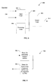
- FIG. 9 shows exemplary provisioning logic 900 for use in aspect of a provisioning system.
- the provisioning logic 900 is implemented by at least one processor or integrated circuit comprising one or more modules configured to provide aspects of a provisioning system as described herein.
- each module comprises hardware, and/or hardware executing software to provide aspects of the provisioning system.
- the provisioning logic 900 comprises a first module that comprises means 902 for means for generating one or more resource entities that represent resource requirements of one or more targeted services, respectively, wherein the resource entities are modeled from at least one of transport network dependent information and transport network independent information.
- the means 902 comprises the processing logic 804.
- the provisioning logic 900 comprises a second module that comprises means 904 for means for determining whether the one or more resource entities can be supported by one or more transport networks.
- the means 904 comprises the processing logic 804.
- DSP digital signal processor
- ASIC application specific integrated circuit
- FPGA field programmable gate array
- a general-purpose processor may be a microprocessor, but, in the alternative, the processor may be any conventional processor, controller, microcontroller, or state machine.
- a processor may also be implemented as a combination of computing devices, e.g., a combination of a DSP and a microprocessor, a plurality of microprocessors, one or more microprocessors in conjunction with a DSP core, or any other such configuration.
- a software module may reside in RAM memory, flash memory, ROM memory, EPROM memory, EEPROM memory, registers, a hard disk, a removable disk, a CD-ROM, or any other form of storage medium known in the art.
- An exemplary storage medium is coupled to the processor, such that the processor can read information from, and write information to, the storage medium.
- the storage medium may be integral to the processor.
- the processor and the storage medium may reside in an ASIC.
- the ASIC may reside in a user terminal.
- the processor and the storage medium may reside as discrete components in a user terminal.
Landscapes
- Engineering & Computer Science (AREA)
- Computer Networks & Wireless Communication (AREA)
- Signal Processing (AREA)
- Data Exchanges In Wide-Area Networks (AREA)
- Mobile Radio Communication Systems (AREA)
Applications Claiming Priority (2)
| Application Number | Priority Date | Filing Date | Title |
|---|---|---|---|
| US94771607P | 2007-07-03 | 2007-07-03 | |
| US11/961,878 US20090010180A1 (en) | 2007-07-03 | 2007-12-20 | Methods and apparatus for resource provisioning and planning in a communication network |
Publications (2)
| Publication Number | Publication Date |
|---|---|
| EP2012464A2 true EP2012464A2 (fr) | 2009-01-07 |
| EP2012464A3 EP2012464A3 (fr) | 2012-01-11 |
Family
ID=39812000
Family Applications (1)
| Application Number | Title | Priority Date | Filing Date |
|---|---|---|---|
| EP08006540A Withdrawn EP2012464A3 (fr) | 2007-07-03 | 2008-03-31 | Procédés et appareil pour fournir et programmer des ressources dans un réseau de communication |
Country Status (5)
| Country | Link |
|---|---|
| US (1) | US20090010180A1 (fr) |
| EP (1) | EP2012464A3 (fr) |
| JP (1) | JP2010532648A (fr) |
| KR (1) | KR20100030668A (fr) |
| CN (1) | CN101690032A (fr) |
Cited By (1)
| Publication number | Priority date | Publication date | Assignee | Title |
|---|---|---|---|---|
| EP2426958A4 (fr) * | 2009-04-29 | 2014-05-28 | Alcatel Lucent | Procédé, bm-sc et station de base pour multiplexage de services mbms dans mbsfn |
Families Citing this family (6)
| Publication number | Priority date | Publication date | Assignee | Title |
|---|---|---|---|---|
| KR100904533B1 (ko) * | 2008-01-11 | 2009-06-25 | 엘지전자 주식회사 | 전송 타이밍 조절 방법, 연속적인 패킷 전송 방법 및 이동통신 단말 |
| ES2405777T3 (es) * | 2008-12-01 | 2013-06-03 | Telefonaktiebolaget Lm Ericsson (Publ) | Agregación de enlace radio |
| US20100250764A1 (en) * | 2009-03-31 | 2010-09-30 | Nokia Corporation | Method and Apparatus for Signaling Layer Information of Scalable Media Data |
| US8683028B2 (en) * | 2012-03-09 | 2014-03-25 | Ciena Corporation | Generic multi-layer provisioning service management layer systems and methods |
| US20140241445A1 (en) * | 2013-02-28 | 2014-08-28 | Univerza V Ljubljani, Fakulteta Za Elektrotehniko | Method for providing quality of service in a multiuser orthogonal frequency division multiplex (OFDM) system |
| CN113133122A (zh) * | 2016-08-12 | 2021-07-16 | 华为技术有限公司 | 业务数据传输的方法、网络设备和终端设备 |
Family Cites Families (13)
| Publication number | Priority date | Publication date | Assignee | Title |
|---|---|---|---|---|
| ZA959722B (en) * | 1994-12-19 | 1996-05-31 | Alcatel Nv | Traffic management and congestion control for packet-based networks |
| US6046981A (en) * | 1997-02-28 | 2000-04-04 | Nec Usa, Inc. | Multi-class connection admission control method for Asynchronous Transfer Mode (ATM) switches |
| JPH10308776A (ja) * | 1997-05-08 | 1998-11-17 | Hitachi Ltd | ネットワークリソース予約方式 |
| EP2273753B1 (fr) * | 1998-12-03 | 2017-10-25 | Rockstar Consortium US LP | Fourniture de politiques de services souhaitées à des abonnés ayant accès à internet |
| JP3710660B2 (ja) * | 1999-12-15 | 2005-10-26 | 株式会社エヌ・ティ・ティ・ドコモ | 移動通信におけるスロット割当て方法及びその方法を使用する基地局並びに移動局 |
| US6721280B1 (en) * | 2000-04-19 | 2004-04-13 | Qualcomm Incorporated | Method and apparatus for voice latency reduction in a voice-over-data wireless communication system |
| EP1304832A1 (fr) * | 2001-10-19 | 2003-04-23 | Alcatel | Distribution des ressources de communication d'un réseau de communication par demande des types qualité de service QoS ou non-QoS de ressources de communication |
| US7363354B2 (en) * | 2001-11-29 | 2008-04-22 | Nokia Corporation | System and method for identifying and accessing network services |
| US7802008B2 (en) * | 2002-08-12 | 2010-09-21 | Matsushita Electric Industrial Co., Ltd. | Quality of service management in network gateways |
| JP2004297157A (ja) * | 2003-03-25 | 2004-10-21 | Samsung Electronics Co Ltd | 無線端末装置および無線統合システム |
| EP1708525A1 (fr) * | 2005-03-31 | 2006-10-04 | Research In Motion Limited | Profil d'itinérance pour dispositifs sans fil |
| US8751649B2 (en) * | 2005-06-07 | 2014-06-10 | Extreme Networks | Port management system |
| CN100391163C (zh) * | 2005-09-02 | 2008-05-28 | 华为技术有限公司 | 基于资源准入控制子系统的资源撤销方法及装置 |
-
2007
- 2007-12-20 US US11/961,878 patent/US20090010180A1/en not_active Abandoned
-
2008
- 2008-03-31 EP EP08006540A patent/EP2012464A3/fr not_active Withdrawn
- 2008-07-02 JP JP2010515266A patent/JP2010532648A/ja active Pending
- 2008-07-02 CN CN200880022993A patent/CN101690032A/zh active Pending
- 2008-07-02 KR KR1020107002522A patent/KR20100030668A/ko not_active Ceased
Cited By (2)
| Publication number | Priority date | Publication date | Assignee | Title |
|---|---|---|---|---|
| EP2426958A4 (fr) * | 2009-04-29 | 2014-05-28 | Alcatel Lucent | Procédé, bm-sc et station de base pour multiplexage de services mbms dans mbsfn |
| US8942154B2 (en) | 2009-04-29 | 2015-01-27 | Alcatel Lucent | Method, BM-SC and base station for multiplexing MBMS services in MBSFN |
Also Published As
| Publication number | Publication date |
|---|---|
| JP2010532648A (ja) | 2010-10-07 |
| US20090010180A1 (en) | 2009-01-08 |
| CN101690032A (zh) | 2010-03-31 |
| KR20100030668A (ko) | 2010-03-18 |
| EP2012464A3 (fr) | 2012-01-11 |
Similar Documents
| Publication | Publication Date | Title |
|---|---|---|
| TWI413388B (zh) | 於網路環境中提供計算負載分配之方法及裝置 | |
| KR101560115B1 (ko) | 멀티플렉싱 및 대역폭 제어 기능을 갖는 신뢰가능한 이벤트 브로드캐스터 | |
| EP2012464A2 (fr) | Procédés et appareil pour fournir et programmer des ressources dans un réseau de communication | |
| CN101854590B (zh) | 无线通信系统中头部压缩的方法和装置 | |
| CN102017492B (zh) | 用于对传输数据块编码以提高切换性能的方法和装置 | |
| CN101422056B (zh) | 使用数据对象普及性测量改进无线广播系统中的服务质量感知的方法和设备 | |
| WO1998009412A1 (fr) | Planification d'une emission de donnees | |
| CN101491009A (zh) | 用于在网络环境中提供测量报告的方法和装置 | |
| EP1867114B1 (fr) | Procede et appareil confortant la remise des contenus via un reseau informatique | |
| WO2009006553A1 (fr) | Procédés et appareil de fourniture et de planification de ressources dans un réseau de communication | |
| Tropea et al. | Two step based QoS scheduler for DVB-S2 satellite system | |
| Kang et al. | Dynamic packet scheduling for cdma2000 1/spl times/EV-DO broadcast and multicast services | |
| CN102137256B (zh) | 一种文件传输方法、装置和系统 | |
| Bai et al. | Class-based packet scheduling to improve QoS for IP video | |
| Pekowsky et al. | Multimedia data broadcasting strategies | |
| Kang et al. | Dynamic scheduling for scalable media transmission over cdma2000 1xEV-DO broadcast and multicast networks | |
| Hefeeda et al. | Energy and Bandwidth Optimization in Mobile Video Streaming Systems | |
| CN120075887A (zh) | 数据传输方法、装置、计算机可读介质及电子设备 | |
| Son | A transmission scheme for streaming variable bit rate video over internet | |
| Chang et al. | Resource Allocation for Stored Video Delivery with Rate Availability Function | |
| Lorquando et al. | Performance Comparison of Scheduling Algorithms for Multimedia Traffic Over High-Rate WPANs | |
| US20110205894A1 (en) | Traffic shaping for real time media streams | |
| HK1114712A (en) | Methods and apparatus for enhanced delivery of content over a data network |
Legal Events
| Date | Code | Title | Description |
|---|---|---|---|
| PUAI | Public reference made under article 153(3) epc to a published international application that has entered the european phase |
Free format text: ORIGINAL CODE: 0009012 |
|
| AK | Designated contracting states |
Kind code of ref document: A2 Designated state(s): AT BE BG CH CY CZ DE DK EE ES FI FR GB GR HR HU IE IS IT LI LT LU LV MC MT NL NO PL PT RO SE SI SK TR |
|
| AX | Request for extension of the european patent |
Extension state: AL BA MK RS |
|
| PUAL | Search report despatched |
Free format text: ORIGINAL CODE: 0009013 |
|
| AK | Designated contracting states |
Kind code of ref document: A3 Designated state(s): AT BE BG CH CY CZ DE DK EE ES FI FR GB GR HR HU IE IS IT LI LT LU LV MC MT NL NO PL PT RO SE SI SK TR |
|
| AX | Request for extension of the european patent |
Extension state: AL BA MK RS |
|
| RIC1 | Information provided on ipc code assigned before grant |
Ipc: H04L 12/56 20060101AFI20111202BHEP |
|
| STAA | Information on the status of an ep patent application or granted ep patent |
Free format text: STATUS: THE APPLICATION IS DEEMED TO BE WITHDRAWN |
|
| 18D | Application deemed to be withdrawn |
Effective date: 20111003 |