EP2012555A1 - Signaltrenneinrichtung, signaltrennverfahren, informationsaufzeichnungsmedium und programm - Google Patents
Signaltrenneinrichtung, signaltrennverfahren, informationsaufzeichnungsmedium und programm Download PDFInfo
- Publication number
- EP2012555A1 EP2012555A1 EP07742607A EP07742607A EP2012555A1 EP 2012555 A1 EP2012555 A1 EP 2012555A1 EP 07742607 A EP07742607 A EP 07742607A EP 07742607 A EP07742607 A EP 07742607A EP 2012555 A1 EP2012555 A1 EP 2012555A1
- Authority
- EP
- European Patent Office
- Prior art keywords
- matrix
- rows
- columns
- repetition
- matrices
- Prior art date
- Legal status (The legal status is an assumption and is not a legal conclusion. Google has not performed a legal analysis and makes no representation as to the accuracy of the status listed.)
- Withdrawn
Links
Images


Classifications
-
- H—ELECTRICITY
- H04—ELECTRIC COMMUNICATION TECHNIQUE
- H04S—STEREOPHONIC SYSTEMS
- H04S3/00—Systems employing more than two channels, e.g. quadraphonic
- H04S3/02—Systems employing more than two channels, e.g. quadraphonic of the matrix type, i.e. in which input signals are combined algebraically, e.g. after having been phase shifted with respect to each other
-
- G—PHYSICS
- G06—COMPUTING OR CALCULATING; COUNTING
- G06F—ELECTRIC DIGITAL DATA PROCESSING
- G06F18/00—Pattern recognition
- G06F18/20—Analysing
- G06F18/21—Design or setup of recognition systems or techniques; Extraction of features in feature space; Blind source separation
- G06F18/213—Feature extraction, e.g. by transforming the feature space; Summarisation; Mappings, e.g. subspace methods
- G06F18/2134—Feature extraction, e.g. by transforming the feature space; Summarisation; Mappings, e.g. subspace methods based on separation criteria, e.g. independent component analysis
-
- G—PHYSICS
- G10—MUSICAL INSTRUMENTS; ACOUSTICS
- G10L—SPEECH ANALYSIS TECHNIQUES OR SPEECH SYNTHESIS; SPEECH RECOGNITION; SPEECH OR VOICE PROCESSING TECHNIQUES; SPEECH OR AUDIO CODING OR DECODING
- G10L21/00—Speech or voice signal processing techniques to produce another audible or non-audible signal, e.g. visual or tactile, in order to modify its quality or its intelligibility
- G10L21/02—Speech enhancement, e.g. noise reduction or echo cancellation
- G10L21/0272—Voice signal separating
Definitions
- the present invention relates to a signal separating device, a signal separating method, a computer-readable information recording medium storing a program that realize the above on a computer or digital signal processor, and the program, which are suitable for improving precision as much as possible and speeding up convergence as much as possible in signal separating technology such as independent component analysis.
- component analysis such as principal component analysis (including component analysis by sphereing), independent component analysis, and non-negative matrix factorization (NMF), wherein, given data strings, the data strings are separated into a plurality of components (such as principal components, independent components, or factors).
- principal component analysis including component analysis by sphereing
- independent component analysis independent component analysis
- NMF non-negative matrix factorization
- such technology is disclosed in a literature such as the following.
- Patent Literature 1 proposes a technology in which principal component analysis or independent component analysis is used to separate a change in the quantity of a chemical substance into a plurality of components, and then uses these components to classify the factors of generation for the chemical substance into groups.
- the observed signal matrix X is then separated into:
- J(X, A, S) wherein X is fixed and A and S are varied
- a combination of A and S is calculated such that the value of J(X, A, S) is minimized (i.e., a minimum.
- the function solves for a maximum or a minimum, or in other words, an "extremum".
- functions that can be used as this cost function include: a function J(X, A, S) that returns the absolute value of the element with the largest absolute value in the matrix (X - AS) (i.e., the maximum absolute value of the elements); a function that returns the average of the squares of each element in the matrix (X - AS); and a function that returns the total sum of the squares of each element in the matrix (X - AS).
- J(X, A, S) that returns the absolute value of the element with the largest absolute value in the matrix (X - AS) (i.e., the maximum absolute value of the elements)
- a function that returns the average of the squares of each element in the matrix (X - AS) i.e., the maximum absolute value of the elements
- X - AS the maximum absolute value of the elements
- a function that returns the average of the squares of each element in the matrix (X - AS) i.e., the maximum absolute value of the elements
- X - AS the maximum absolute value of
- the present invention is made to solve the foregoing problems, and its object is to provide a signal separating device, a signal separating method, and a computer-readable information recording medium storing a program that realizes the above on a computer or digital signal processor, and the program, which are suitable for improving precision as much as possible and speeding up convergence as much as possible in signal separating technology such as independent component analysis.
- the signal separating device is configured as follows.
- the iterative estimator operates with respect to a matrix function J(•, •, •) that takes a matrix having m rows and T columns, a matrix having m rows and n columns, and a matrix having n rows and T columns, and returns a scalar value.
- the iterative estimator Upon receiving a matrix having m rows and T columns, a matrix having m rows and n columns, and a matrix having n rows and T columns, the iterative estimator iteratively estimates, through a predetermined number of repetitions, a combination of arguments, which are a matrix having m rows and n columns and a matrix having n rows and T columns, whereby the scalar value returned by the matrix function J(•, •, •) is extremized when the matrix having m rows and T columns is fixed.
- the repeating calculator calculates, by repetition, L number of matrices A 1 , A 2 , A 3 , ..., A L such that c ⁇ A 1 , c ⁇ A 2 , c ⁇ A 3 , c ⁇ ... , c ⁇ A L - 1 ⁇ A L ... yields a matrix of m rows and n columns.
- the iterative estimator is thereby caused to make iterative estimations with respect to the matrix function J i (•, •, •) that takes a matrix having m rows and T columns, a matrix having m rows and n columns, and a matrix having n rows and T columns and then returns a scalar value.
- the repeating calculator then takes the resulting matrix of m rows and n columns to be A i , and also takes the matrix of n rows and T columns to be S i .
- the result output unit then takes the matrix S L of n rows and T columns calculated above to be the source signal matrix S of n rows and T columns, and then outputs the matrices A and S.
- the signal separating device of the present invention may be further provided with a repetition controller configured as follows.
- the repetition controller causes the repeating calculator to re-calculate repetitions until the calculated L number of matrices A 1 , A 2 , A 3 , ..., A L and the matrix S L of n rows and T columns satisfy a predetermined convergence condition.
- the repetition controller causes the A i from the last repetition before the re-calculation and the S i from the last repetition before the re-calculation to be supplied as the predefined initial value matrix of m rows and n columns and the predefined initial value matrix of n rows and T columns for the i-th repetition.
- the result output unit calculates and then outputs the matrices A and S.
- the predefined matrix operation c(•, •) may be defined as a matrix product operation.
- the predefined matrix operation c(•, •) may be defined as a convolution operation.
- the predefined matrix operation c(•, •) may be defined as a non-linear link function.
- the signal separating method comprises an iterative estimation step, a repeating calculation step, and a result output step, and is configured as follows.
- the iterative estimator operates with respect to a matrix function J(•, •, •) that takes a matrix having m rows and T columns, a matrix having m rows and n columns, and a matrix having n rows and T columns, and returns a scalar value.
- the iterative estimator Upon receiving a matrix having m rows and T columns, a matrix having m rows and n columns, and a matrix having n rows and T columns, the iterative estimator iteratively estimates, through a predetermined number of repetitions, a combination of arguments, which are a matrix having m rows and n columns and a matrix having n rows and T columns, whereby the scalar value returned by the matrix function J(•, •, •) is extremized when the matrix having m rows and T columns is fixed.
- the repeating calculator calculates, by repetition, L number of matrices A 1 , A 2 , A 3 , ..., A L such that c ⁇ A 1 , c ⁇ A 2 , c ⁇ A 3 , c ⁇ ... , c ⁇ A L - 1 ⁇ A L ... yields a matrix of m rows and n columns.
- the iterative estimator is thereby caused to make iterative estimations with respect to the matrix function J i (•, •, •) that takes a matrix having m rows and T columns, a matrix having m rows and n columns, and a matrix having n rows and T columns and then returns a scalar value.
- the repeating calculator then takes the resulting matrix of m rows and n columns to be A i , and also takes the matrix of n rows and T columns to be S i .
- the result output unit then takes the matrix S L of n rows and T columns calculated above to be the source signal matrix S of n rows and T columns, and then outputs the matrices A and S.
- the signal separating device may further include a repetition controller configured as follows, and the signal separating method may further comprise a repetition controlling step and be configured as follows.
- the repetition controller causes the repeating calculator to re-calculate repetitions until the calculated L number of matrices A 1 , A 2 , A 3 , ..., A L and the matrix S L of n rows and T columns satisfy a predetermined convergence condition.
- the repetition controller causes the A i from the last repetition before the re-calculation and the S i from the last repetition before the re-calculation to be supplied as the predefined initial value matrix of m rows and n columns and the predefined initial value matrix of n rows and T columns for the i-th repetition.
- the result output step if the predetermined convergence condition is met, then the matrices A and S are calculated and output.
- a program according to another aspect of the present invention causes a computer or digital signal processor to function as the respective components of the above signal separating device, or alternatively, causes the above signal separating method to be executed.
- the program of the present invention may be recorded onto a computer-readable information recording medium, such as a compact disc, a flexible disk, a hard disk, a magneto-optical disk, a digital video disc, magnetic tape, or semiconductor memory.
- a computer-readable information recording medium such as a compact disc, a flexible disk, a hard disk, a magneto-optical disk, a digital video disc, magnetic tape, or semiconductor memory.
- the above program may be distributed or sold via a computer communications network independently of the computer or digital signal processor upon which the program is executed.
- the above information recording medium may also be distributed or sold independently of the computer or digital signal processor.
- a signal separating device a signal separating method, a computer-readable information recording medium storing a program that realizes the above on a computer or digital signal processor, and the program can be provided, which are suitable for improving precision as much as possible and speeding up convergence as much as possible in signal separating technology such as independent component analysis.
- independent component analysis is given as an example of a component analysis technique.
- the component analysis technique may be replaced with principal component analysis (including component analysis by sphereing) or non-negative matrix factorization, and such embodiments are also to be included within the scope of the present invention.
- matrix operation c(•, •) is described by way of example as a matrix product in order to ease understanding.
- matrix convolutions and various non-linear matrix link functions may also be used, and cases wherein such functions are adopted are also to be included within the scope of the present invention.
- the following matrix X is used as the input for signal separation.
- the following may be used as the above cost function: a function that returns the absolute value of the element with the largest absolute value in the matrix (X - AS) (i.e., the maximum absolute value of the elements), a function that returns the average of the squares of each element in the matrix (X - AS), or a function that returns the total sum of the squares of each element in the matrix (X - AS).
- X - AS the largest absolute value in the matrix
- other functions such as Amari's ⁇ -divergence, Kullback-Leibler divergence, the Frobenius norm, and Jenssen-Shannon divergence may also be used.
- an iterative method (such as the gradient method, the conjugate gradient method, or Newton's method) is adopted as the computational technique to solve for the above matrices A and S.
- this method is iterated until A and S meet a predefined iteration termination condition.
- the iteration termination condition to be satisfied may be such that the ratio of the total sum of the squares of the differences in the elements of A and S before and after an iteration with respect to the total sum of the squares of the elements in the matrices becomes less than a predetermined value ⁇ .
- the number of iterations may also be fixed to a certain number. This latter case is equivalent to specifying "Number of iterations: xx " as the iteration termination condition.
- Computation may also be conducted by applying constraints based on already known properties of the signal to be analyzed. These constraints may include non-negativity, sparseness, space-time decorrelation, smoothness, and independence.
- the iterative estimator a single computational module referred to as the iterative estimator is taken to perform the functions of conducting independent component analysis like the above.
- a variety of independent component analysis techniques as well as existing techniques can be applied to the processes executed by the iterative estimator.
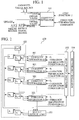
- FIG. 1 is an explanatory diagram illustrating input and output with respect to the iterative estimator. The description hereinafter will refer to this diagram.
- An iterative estimator 101 is realized by cooperation between a general computer CPU (Central Processing Unit) and a storage device such as RAM (Random Access Memory).
- a general computer CPU Central Processing Unit
- RAM Random Access Memory
- the matrices X, A, and S are provided to the iterative estimator 101 as input.
- the matrices X, A, and S are stored in the RAM or similar memory.
- the present embodiment is configured such that the addresses of the matrices X, A, and S stored in memory are passed as arguments to the library (program) functions that realize the iterative estimator 101.
- the matrix X herein is equivalent to an observed signal matrix as described above, in a broader sense the matrix X can be thought of as a constant matrix that defines the conditions involved in the iterative method.
- the matrices A and S provided herein are the mixing matrix and the source signal matrix, in a broader sense these can be thought of as the initial values that approximate the true values in the iterative method. Consequently, it is necessary for the matrices A and S stored in the RAM or similar memory to be initialized with some set of values.
- the iterative estimator 101 may also take the output result from the previous process as the initial values, this being preferable in many cases.
- the cost function and the termination condition are also provided to the iterative estimator 101. These may be specified directly in the code (program) used to realize the iterative estimator 101, or may be provided by specifying the address of a library function.
- the iterative estimator 101 receives the various information described above, iterates until the iteration termination condition is satisfied, and then outputs the matrices A' and S', the values thereof being closer to the true values than the matrices A and S that were provided as input.
- the matrices A' and S' being output is equivalent to the iteration termination condition being met.
- the following are given as examples of the iteration termination condition.
- output result and the output method involve overwriting the region in the RAM or similar memory where the matrices A and S that were provided as input are stored, the region being overwritten with the content of A' and S' (given in the diagram as "Overwrite”).
- the present embodiment primarily adopts such a configuration.
- the cost function J(X, A, S) is treated as a combination of two cost functions K(X, A, S) and H(X, A, S).
- K(•, •, •) and H(•, •, •) may be selected to be identical cost functions (i.e., the three cost functions K, H, and J are the same), or suitably different cost functions may be selected.
- a single iteration of the iterative method is thus typically:
- a single iteration of the iterative method may also involve the inverse:
- the iterative estimator 101 as described above is used at least L number of times (L ⁇ 2) via a subroutine call, but the provided arguments and other parameters in this case may differ.
- L ⁇ 2 the number of times (L ⁇ 2) via a subroutine call
- FIG. 2 is a schematic diagram illustrating the configuration of a signal separating device according to the present embodiment. The description hereinafter will refer to this diagram.
- a signal separating device 100 is provided with L number of iterative estimators 101, a repeating calculator 102, a result output unit 103, a repetition controller 104, as well as a storage unit 105.
- L is equivalent to the "step number” or "layer number”.
- regions for storing the following information are reserved.
- the source signal matrix S having n rows and T columns and being one of the results of signal separation, can also be identified as S L .
- the L number of matrices A 1 , ..., A L are defined such that the predefined operation c(•, •) c ⁇ A 1 , c ⁇ A 2 , c ⁇ A 3 , c ⁇ ... , c ⁇ A L - 1 ⁇ A L ... yields a matrix of m rows and n columns.
- the matrix product is used as c(•, •).
- FIG. 3 is a flowchart illustrating the control flow of the signal separating process executed in the signal separating device. The description hereinafter will refer to this diagram.
- the values of the observed signal that acts as the input are set in the matrix X (i.e., the matrix S 0 ) (step S301).
- the matrices S 1 , S 2 , ..., S L-1 , S L are initialized with suitable values (step S302).
- the matrix S L can be identified as the matrix S.
- the matrices A 1 , A 2 , ..., A L-1 , A L are initialized with suitable values (step S303).
- the repetition controller 104 repeats the following processes of step S304 to step S308 (step S304) as long as the convergence condition is not satisfied (step S308).
- a variety of conditions similar to the iteration termination condition may be adopted as the convergence condition.
- the convergence condition is considered to be satisfied when variation in the matrices S 1 , ..., S L and the matrices A 1 , ..., A L between respective repetitions has become exceedingly small.
- the convergence condition by which the terminus of the repetition is determined may also be set to always be true. In this case, the repetition is conducted only once, and in practice this simply reduces to serial processing.
- repetition controller 104 is realized by the CPU cooperating with the RAM or similar memory.
- the repeating calculator 102 increases a counter variable i by 1 per repetition from an initial value of 1 until the final value of L is reached (step S305).
- the repeating calculator 102 is realized by the CPU working in conjunction with the RAM or similar memory.
- the i-th iterative estimator 101 provides the matrices S i-1 , A i , and S i as input, and then causes the computational processing of the foregoing iterative method to be conducted (step S306).
- step S306 the computational processing of the iterative method in step S306 is repeated until an iteration termination condition is satisfied, but the selection of the iteration termination condition may be varied to suit a specific field or goal of application.
- the matrices A i and S i are the matrices whose values have become closer to the "actual values" via the iterative method in the processing in step S306. Moreover, as described above, the estimated results of the iterative estimator 101 for this iteration are stored in the storage regions A i and S i .
- step S307 values with a higher accuracy than the initial values set in the matrices S 1 , ..., S L and the matrices A 1 , ..., A L in steps S302 and S303 are stored in the same regions thereof.
- step S304 By testing these values it is then determined whether or not the convergence condition has been satisfied. If the convergence condition has not been satisfied, the process returns to step S304 and continues to be repeated (step S308).
- the CPU working in conjunction with the RAM or similar memory, functions as the result output unit.
- the matrix product in step S309 is equivalent to solving for the matrix A as shown above.
- a matrix convolution operation is considered as the operation c(•, •)
- a tensor operation taking into account two-dimensional matrices (i.e., second order tensors) and three-dimensional matrices (i.e., third order tensors) is to be conducted.
- the matrix subject to this convolution operation is referred to as the mixing operator.
- the mixing matrix A is a three-dimensional matrix.
- the elements of a three-dimensional matrix are expressed in the form [•, •, •] similar to the above.
- the values of regions where elements are undefined are taken to be 0, and the subscript of ⁇ indicates that a sum is to be taken over the entire indicated range of the indices in the tensor.
- Equation 1 a convolution of a third-order tensor A and a second-order tensor S is defined as shown in Equation 1.
- Equation 2 a convolution of a third-order tensor A and a third-order tensor B is defined as shown in Equation 2.
- f(•) typically a step function that is smooth in the vicinity of the origin as that is often used in the field of neural networks may be used.
- Test 1 involves comparing signal separations corresponding to sound waves emitted from a plurality of sound sources (more commonly, the propagation of a source signal emitted from a signal source) as collected by a microphone positioned nearby (more commonly, the observed signal obtained by observing the propagation with a receiver or a sensor). In the following, testing is conducted using benchmark data used in the field of signal separation obtained by NMF (non-negative matrix factorization).
- FIG. 4 is a graph showing the nature of the waveforms of the source signal.
- FIG. 5 is a graph showing the nature of the waveforms of the observed signal.
- FIG. 7 is a graph of the waveforms in the case where independent component analysis is conducted on the four signals via the conventional technique.
- Test 2 illustrates signal separation in the case where a large amount of noise is present.
- FIG. 8 is a graph showing the nature of the waveforms of the source signal.
- FIG. 9 is a graph showing the nature of the waveforms of the observed signal.
- the noise level is very high, and thus it can be seen that noise is also present in the observed signal, as shown in FIG. 9 .
- FIG. 11 is a graph showing SIR (Signal to Interference Ratio) values.
- FIG. 12 shows the waveforms obtained using the conventional technique of the NMF Lee-Seung algorithm.
- the conventional technique yields SIR values of less than 8 dB, and thus the high capability of the technique of the present embodiment is apparent.
- Test 3 is an application to image processing.
- FIG. 13 is a diagram showing the images which act as the source signal.
- FIG. 14 is a diagram showing the images corresponding to the observed signal.
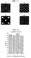
- FIG. 17 shows the source signal images obtained using the conventional technique of the NMF Lee-Seung algorithm.
- FIG. 18 is a graph showing the SIR values of the signal from the technique of the present embodiment.
- FIG. 13 there are four source signals, and as shown in FIG. 14 , these are observed using nine channels.
- a signal separating device and a signal separating method it is possible to provide a signal separating device and a signal separating method, a computer-readable information recording medium storing a program that realizes the above on a computer or digital signal processor, and the program, which are suitable for improving precision as much as possible and speeding up convergence as much as possible in signal separating technology such as independent component analysis.
Landscapes
- Engineering & Computer Science (AREA)
- Physics & Mathematics (AREA)
- Theoretical Computer Science (AREA)
- Computer Vision & Pattern Recognition (AREA)
- Data Mining & Analysis (AREA)
- Acoustics & Sound (AREA)
- Signal Processing (AREA)
- General Physics & Mathematics (AREA)
- Bioinformatics & Computational Biology (AREA)
- Audiology, Speech & Language Pathology (AREA)
- General Engineering & Computer Science (AREA)
- Evolutionary Biology (AREA)
- Bioinformatics & Cheminformatics (AREA)
- Computational Linguistics (AREA)
- Quality & Reliability (AREA)
- Artificial Intelligence (AREA)
- Health & Medical Sciences (AREA)
- Evolutionary Computation (AREA)
- Human Computer Interaction (AREA)
- Life Sciences & Earth Sciences (AREA)
- Multimedia (AREA)
- Algebra (AREA)
- Mathematical Analysis (AREA)
- Mathematical Optimization (AREA)
- Mathematical Physics (AREA)
- Pure & Applied Mathematics (AREA)
- Complex Calculations (AREA)
Applications Claiming Priority (2)
| Application Number | Priority Date | Filing Date | Title |
|---|---|---|---|
| JP2006124167A JP4952979B2 (ja) | 2006-04-27 | 2006-04-27 | 信号分離装置、信号分離方法、ならびに、プログラム |
| PCT/JP2007/059172 WO2007126054A1 (ja) | 2006-04-27 | 2007-04-27 | 信号分離装置、信号分離方法、情報記録媒体、ならびに、プログラム |
Publications (2)
| Publication Number | Publication Date |
|---|---|
| EP2012555A1 true EP2012555A1 (de) | 2009-01-07 |
| EP2012555A4 EP2012555A4 (de) | 2011-06-08 |
Family
ID=38655575
Family Applications (1)
| Application Number | Title | Priority Date | Filing Date |
|---|---|---|---|
| EP07742607A Withdrawn EP2012555A4 (de) | 2006-04-27 | 2007-04-27 | Signaltrenneinrichtung, signaltrennverfahren, informationsaufzeichnungsmedium und programm |
Country Status (4)
| Country | Link |
|---|---|
| US (1) | US8285773B2 (de) |
| EP (1) | EP2012555A4 (de) |
| JP (1) | JP4952979B2 (de) |
| WO (1) | WO2007126054A1 (de) |
Cited By (1)
| Publication number | Priority date | Publication date | Assignee | Title |
|---|---|---|---|---|
| WO2016130885A1 (en) * | 2015-02-15 | 2016-08-18 | Dolby Laboratories Licensing Corporation | Audio source separation |
Families Citing this family (10)
| Publication number | Priority date | Publication date | Assignee | Title |
|---|---|---|---|---|
| JP4958241B2 (ja) * | 2008-08-05 | 2012-06-20 | 日本電信電話株式会社 | 信号処理装置、信号処理方法、信号処理プログラムおよび記録媒体 |
| US8340943B2 (en) * | 2009-08-28 | 2012-12-25 | Electronics And Telecommunications Research Institute | Method and system for separating musical sound source |
| KR101225932B1 (ko) | 2009-08-28 | 2013-01-24 | 포항공과대학교 산학협력단 | 음악 음원 분리 방법 및 장치 |
| KR101272972B1 (ko) | 2009-09-14 | 2013-06-10 | 한국전자통신연구원 | 음원 데이터베이스를 사용하지 않는 음악 음원 분리 방법 및 장치 |
| KR20120031854A (ko) * | 2010-09-27 | 2012-04-04 | 한국전자통신연구원 | 시간 및 주파수 특징을 이용하는 음악 음원 분리 장치 및 방법 |
| JP6054142B2 (ja) * | 2012-10-31 | 2016-12-27 | 株式会社東芝 | 信号処理装置、方法およびプログラム |
| US9668066B1 (en) * | 2015-04-03 | 2017-05-30 | Cedar Audio Ltd. | Blind source separation systems |
| CN109192220B (zh) * | 2018-08-02 | 2022-11-11 | 福建师范大学福清分校 | 一种比例微分控制的混合信号自适应快速分离方法 |
| CN110969248B (zh) * | 2018-09-28 | 2023-04-07 | 中国石油化工股份有限公司 | 基于rbf-a2c的强化学习方法及系统 |
| CN110269609B (zh) * | 2019-07-08 | 2021-09-28 | 江苏理工学院 | 基于单通道的脑电信号中眼电伪迹分离方法 |
Family Cites Families (9)
| Publication number | Priority date | Publication date | Assignee | Title |
|---|---|---|---|---|
| US6535666B1 (en) * | 1995-06-02 | 2003-03-18 | Trw Inc. | Method and apparatus for separating signals transmitted over a waveguide |
| US6026217A (en) * | 1996-06-21 | 2000-02-15 | Digital Equipment Corporation | Method and apparatus for eliminating the transpose buffer during a decomposed forward or inverse 2-dimensional discrete cosine transform through operand decomposition storage and retrieval |
| US7158559B2 (en) * | 2002-01-15 | 2007-01-02 | Tensor Comm, Inc. | Serial cancellation receiver design for a coded signal processing engine |
| JP3817161B2 (ja) * | 2001-11-05 | 2006-08-30 | 独立行政法人理化学研究所 | 化学物質分類装置、化学物質分類方法、ならびに、プログラム |
| JP3786038B2 (ja) * | 2002-03-14 | 2006-06-14 | 日産自動車株式会社 | 入力信号処理方法および入力信号処理装置 |
| GB0229473D0 (en) * | 2002-12-18 | 2003-01-22 | Qinetiq Ltd | Signal separation system and method |
| US7039546B2 (en) * | 2003-03-04 | 2006-05-02 | Nippon Telegraph And Telephone Corporation | Position information estimation device, method thereof, and program |
| FI20031079A0 (fi) * | 2003-07-16 | 2003-07-16 | Nokia Corp | Menetelmä tiedonsiirtoresurssien kontrolloimiseksi, sekä kontrolleri |
| KR100580843B1 (ko) * | 2003-12-22 | 2006-05-16 | 한국전자통신연구원 | V―blast에서 채널전달함수행렬 처리장치 및 그의처리방법 |
-
2006
- 2006-04-27 JP JP2006124167A patent/JP4952979B2/ja not_active Expired - Fee Related
-
2007
- 2007-04-27 WO PCT/JP2007/059172 patent/WO2007126054A1/ja not_active Ceased
- 2007-04-27 US US12/226,651 patent/US8285773B2/en not_active Expired - Fee Related
- 2007-04-27 EP EP07742607A patent/EP2012555A4/de not_active Withdrawn
Non-Patent Citations (10)
| Title |
|---|
| ANDRZEJ CICHOCKI ET AL: "Extended SMART Algorithms for Non-negative Matrix Factorization", ARTIFICIAL INTELLIGENCE AND SOFT COMPUTING - ICAISC 2006, ZAKOPANE, POLAND, LECTURE NOTES IN ARTIFICIAL INTELLIGENCE, SPRINGER,, vol. 4029, 25 July 2006 (2006-07-25), pages 548-562, XP019035756, ISBN: 978-3-540-35748-3 * |
| CHIPPERFIELD ANDREW, FLEMING PETER, POHLHEIM HARTMUT, FONSECA CARLOS: 'Genetic Algorithm TOOLBOX', [Online] 1994, DEPARTMENT OF AUTOMATIC CONTROL AND SYSTEMS ENGINEERING, UNIVERSITY OF SHEFFIELD, pages 1 - 22 Retrieved from the Internet: <URL:http://citeseerx.ist.psu.edu/viewdoc/summary?doi=10.1.1.16.1178> [retrieved on 2013-00-00] * |
| Cichoci A, Amari S-I: "Adaptive Blind Signal and Image Processing - Learning Algorithms and Applications", 2002, John Wiley & Sons, Hoboken, US, XP002634761, ISBN: 978-0-471-60791-5 pages 5,6,15-16,44, * equation 1.1; figure 1.3 * * equation 1.10; figure 1.9 * * equation 2.5 * * |
| Cichocki A, Zdunek R, Phan A-H, Amari S-I: "Nonnegative Matrix and Tensor Factorizations - Applications to Exploratory Multi-way Data Analysis and Blind Source Separation", 2009, John Wiley & Sons, Chichester, GB, XP002634759, ISBN: 978-0-470-74666-0 page 14, * section 1.2.8 * * |
| Haykin S (Ed.): "Unsupervised Adaptive Filtering - Volume 1 - Blind Source Separation", 2000, John Wiley & Sons, New York, US, XP002634762, ISBN: 0-471-29412-8 pages 258-259, * section 6.4 * * |
| JONG-HOON A ET AL: "Multiple nonnegative-matrix factorization of dynamic pet images", PROCEEDINGS OF THE 6TH ASIAN CONFERENCE ON COMPUTER VISION (ACCV '04), January 2004 (2004-01), pages 1009-1013, XP002634758, Jeju Island, Korea * |
| KURT STADLTHANNER ET AL: "Hybridizing Sparse Component Analysis with Genetic Algorithms for Blind Source Separation", BIOLOGICAL AND MEDICAL DATA ANALYSIS LECTURE NOTES IN COMPUTER SCIENCE;LECTURE NOTES IN BIOINFORMATICS;LNCS, SPRINGER, BERLIN, DE, vol. 3745, 1 January 2005 (2005-01-01), pages 137-148, XP019022506, ISBN: 978-3-540-29674-4 * |
| LEE D D ET AL: "LEARNING THE PARTS OF OBJECTS BY NON-NEGATIVE MATRIX FACTORIZATION", NATURE, NATURE PUBLISHING GROUP, LONDON, GB, vol. 401, no. 6755, 21 October 1999 (1999-10-21), pages 788-791, XP008056832, ISSN: 0028-0836, DOI: DOI:10.1038/44565 * |
| Plumbley M D, Cichocki A, Bro R: "Chapter 13 - Non-negative mixtures" In: Comon P, Jutten C: "Handbook of Blind Source Separation - Independent component Analysis and Applications", 2010, Academic Press, Oxford, GB, XP002634760, ISBN: 978-0-12-374726-6 pages 515,529-530, * section 13.3.4.1 * * |
| See also references of WO2007126054A1 * |
Cited By (2)
| Publication number | Priority date | Publication date | Assignee | Title |
|---|---|---|---|---|
| WO2016130885A1 (en) * | 2015-02-15 | 2016-08-18 | Dolby Laboratories Licensing Corporation | Audio source separation |
| US10192568B2 (en) | 2015-02-15 | 2019-01-29 | Dolby Laboratories Licensing Corporation | Audio source separation with linear combination and orthogonality characteristics for spatial parameters |
Also Published As
| Publication number | Publication date |
|---|---|
| US8285773B2 (en) | 2012-10-09 |
| JP4952979B2 (ja) | 2012-06-13 |
| US20090234901A1 (en) | 2009-09-17 |
| EP2012555A4 (de) | 2011-06-08 |
| JP2007298564A (ja) | 2007-11-15 |
| WO2007126054A1 (ja) | 2007-11-08 |
Similar Documents
| Publication | Publication Date | Title |
|---|---|---|
| EP2012555A1 (de) | Signaltrenneinrichtung, signaltrennverfahren, informationsaufzeichnungsmedium und programm | |
| US20220150661A1 (en) | Audio processing apparatus and method for denoising a multi-channel audio signal | |
| Murata et al. | An approach to blind source separation based on temporal structure of speech signals | |
| EP3832498B1 (de) | Vorrichtung und verfahren zur durchführung einer matrixmultiplikationsoperation eines neuronalen netzes | |
| US8364483B2 (en) | Method for separating source signals and apparatus thereof | |
| EP3257044B1 (de) | Trennung von audioquellen | |
| EP3494575B1 (de) | Vorrichtungen und verfahren zur beurteilung der sprachqualität | |
| HK1244104A1 (en) | Audio source separation | |
| EP1290816B1 (de) | Verfahren zur signalgewinnung | |
| EP2312576A2 (de) | Verfahren und System zur Verringerung der Dimensionalität eines von einer Reihe unabhängiger Prozesse erzeugten Signalspektrogramms | |
| US20220415454A1 (en) | Systems and Methods for Estimating Treatment Effects in Randomized Trials Using Covariate Adjusted Stratification and Pseudovalue Regression | |
| US10818302B2 (en) | Audio source separation | |
| EP2731359A1 (de) | Audioverarbeitungsvorrichtung, Verfahren und Programm | |
| US10893373B2 (en) | Processing of a multi-channel spatial audio format input signal | |
| EP3392883A1 (de) | Verfahren zur verarbeitung von audiosignalen und entsprechende elektronische vorrichtung, übergangsloses computerlesbares programmprodukt und computerlesbares speichermedium | |
| JP2019144511A (ja) | 音響信号モデル学習装置、音響信号解析装置、方法、及びプログラム | |
| US9269359B2 (en) | Coding of multi-channel signals | |
| KR101043114B1 (ko) | 소리의 복원 방법, 소리의 복원 방법을 기록한 기록매체 및 소리의 복원 방법을 수행하는 장치 | |
| EP4506940A1 (de) | Verfahren und vorrichtung zur merkmalsrepräsentationsextraktion, vorrichtung, medium und programmprodukt | |
| US10885928B1 (en) | Mixed domain blind source separation for sensor array processing | |
| CN101399708A (zh) | 一种建立网络性能模型的方法和设备 | |
| CN114282572B (zh) | 一种基于ShuffleNet V2分类网络和梅尔谱特征的水声目标识别方法 | |
| Moliner et al. | Unsupervised estimation of nonlinear audio effects: Comparing diffusion-based and adversarial approaches | |
| Hu et al. | An HMM compensation approach using unscented transformation for noisy speech recognition | |
| US10540992B2 (en) | Deflation and decomposition of data signals using reference signals |
Legal Events
| Date | Code | Title | Description |
|---|---|---|---|
| PUAI | Public reference made under article 153(3) epc to a published international application that has entered the european phase |
Free format text: ORIGINAL CODE: 0009012 |
|
| 17P | Request for examination filed |
Effective date: 20081027 |
|
| AK | Designated contracting states |
Kind code of ref document: A1 Designated state(s): AT BE BG CH CY CZ DE DK EE ES FI FR GB GR HU IE IS IT LI LT LU LV MC MT NL PL PT RO SE SI SK TR |
|
| AX | Request for extension of the european patent |
Extension state: AL BA HR MK RS |
|
| A4 | Supplementary search report drawn up and despatched |
Effective date: 20110510 |
|
| DAX | Request for extension of the european patent (deleted) | ||
| 17Q | First examination report despatched |
Effective date: 20131107 |
|
| STAA | Information on the status of an ep patent application or granted ep patent |
Free format text: STATUS: THE APPLICATION IS DEEMED TO BE WITHDRAWN |
|
| 18D | Application deemed to be withdrawn |
Effective date: 20140318 |