EP2012558A2 - Procédé et dispositif destinés à déterminer une réaction d'impulsion acoustique dans le domaine temporel - Google Patents
Procédé et dispositif destinés à déterminer une réaction d'impulsion acoustique dans le domaine temporel Download PDFInfo
- Publication number
- EP2012558A2 EP2012558A2 EP08012163A EP08012163A EP2012558A2 EP 2012558 A2 EP2012558 A2 EP 2012558A2 EP 08012163 A EP08012163 A EP 08012163A EP 08012163 A EP08012163 A EP 08012163A EP 2012558 A2 EP2012558 A2 EP 2012558A2
- Authority
- EP
- European Patent Office
- Prior art keywords
- acoustic
- impulse response
- room
- signal
- time
- Prior art date
- Legal status (The legal status is an assumption and is not a legal conclusion. Google has not performed a legal analysis and makes no representation as to the accuracy of the status listed.)
- Withdrawn
Links
- 238000000034 method Methods 0.000 title claims abstract description 60
- 230000004044 response Effects 0.000 claims abstract description 145
- 238000004590 computer program Methods 0.000 claims abstract 2
- 238000011156 evaluation Methods 0.000 claims description 42
- 238000004364 calculation method Methods 0.000 claims description 31
- 238000005259 measurement Methods 0.000 claims description 24
- 238000001514 detection method Methods 0.000 claims description 15
- 238000005516 engineering process Methods 0.000 claims description 14
- 238000001228 spectrum Methods 0.000 claims description 9
- 238000012935 Averaging Methods 0.000 claims description 8
- 238000012545 processing Methods 0.000 claims description 8
- 230000001960 triggered effect Effects 0.000 claims description 6
- 230000002123 temporal effect Effects 0.000 claims description 4
- 230000002411 adverse Effects 0.000 claims description 3
- 230000006870 function Effects 0.000 description 13
- 230000008569 process Effects 0.000 description 12
- 238000012546 transfer Methods 0.000 description 11
- 239000000872 buffer Substances 0.000 description 7
- 238000010586 diagram Methods 0.000 description 7
- 230000005284 excitation Effects 0.000 description 7
- 230000000875 corresponding effect Effects 0.000 description 6
- 238000004458 analytical method Methods 0.000 description 5
- 238000011161 development Methods 0.000 description 5
- 238000012512 characterization method Methods 0.000 description 4
- 238000012360 testing method Methods 0.000 description 4
- 230000008859 change Effects 0.000 description 3
- 230000003068 static effect Effects 0.000 description 3
- 230000005540 biological transmission Effects 0.000 description 2
- 230000008030 elimination Effects 0.000 description 2
- 238000003379 elimination reaction Methods 0.000 description 2
- 230000003993 interaction Effects 0.000 description 2
- 230000007246 mechanism Effects 0.000 description 2
- 230000003595 spectral effect Effects 0.000 description 2
- 230000009466 transformation Effects 0.000 description 2
- 229920002472 Starch Polymers 0.000 description 1
- 241000746422 Stipa Species 0.000 description 1
- 230000006978 adaptation Effects 0.000 description 1
- 230000006399 behavior Effects 0.000 description 1
- ZYXYTGQFPZEUFX-UHFFFAOYSA-N benzpyrimoxan Chemical compound O1C(OCCC1)C=1C(=NC=NC=1)OCC1=CC=C(C=C1)C(F)(F)F ZYXYTGQFPZEUFX-UHFFFAOYSA-N 0.000 description 1
- 230000003139 buffering effect Effects 0.000 description 1
- 239000000470 constituent Substances 0.000 description 1
- 230000002596 correlated effect Effects 0.000 description 1
- 230000007423 decrease Effects 0.000 description 1
- 230000001419 dependent effect Effects 0.000 description 1
- 238000011143 downstream manufacturing Methods 0.000 description 1
- 230000006872 improvement Effects 0.000 description 1
- 230000002452 interceptive effect Effects 0.000 description 1
- 238000011835 investigation Methods 0.000 description 1
- 238000007726 management method Methods 0.000 description 1
- 230000008447 perception Effects 0.000 description 1
- 238000010223 real-time analysis Methods 0.000 description 1
- 238000000926 separation method Methods 0.000 description 1
- 235000019698 starch Nutrition 0.000 description 1
- 239000008107 starch Substances 0.000 description 1
Images







Classifications
-
- H—ELECTRICITY
- H04—ELECTRIC COMMUNICATION TECHNIQUE
- H04S—STEREOPHONIC SYSTEMS
- H04S7/00—Indicating arrangements; Control arrangements, e.g. balance control
-
- G—PHYSICS
- G01—MEASURING; TESTING
- G01H—MEASUREMENT OF MECHANICAL VIBRATIONS OR ULTRASONIC, SONIC OR INFRASONIC WAVES
- G01H7/00—Measuring reverberation time ; room acoustic measurements
Definitions
- the invention relates to technologies for determining a room acoustic impulse response in the time domain.
- Determining an acoustic impulse response is a task associated with various applications. These include, on the one hand, the non-acoustical examination of a test system, for example the characterization of loudspeakers or other acoustic signal sources, and on the other hand the room acoustics examination of a test system, in particular the analysis of the acoustics of premises, in which a room acoustic impulse response or acoustic room impulse response is determined.
- an input signal from an acoustic signal source is provided and radiated.
- the input signal is emitted from the speaker.
- the injected acoustic input signal "folds" with the impulse response of the system to be analyzed.
- the result is an acoustic output signal.
- the acoustic output signal can then be measured with an acoustic measuring device, for example a microphone.
- inverse Fourier transformation it is then possible to easily determine the acoustic impulse response h (t) in the time domain.
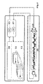
- Fig. 1 shows a schematic representation for explaining a known measuring arrangement for determining an acoustic impulse response.
- a control device 1 comprising a signal generator 1a and an evaluation device 1b
- acoustic signals are generated, which are, for example, noise signals, sweeps, speech signals or music signals which are transmitted via a digital-to-analog converter 2 (DA converter).
- DA converter digital-to-analog converter 2
- an acoustic signal source 3 via which an acoustic input signal 4 is delivered.
- an acoustic output signal is detected and transferred via an analog-to-digital converter 6 (AD converter) to the evaluation device 1 b, which in the representation in Fig. 1 is integrated together with a signal generator 1a.
- AD converter analog-to-digital converter
- acoustic impulse response has in common that first the acoustic output signal is detected in a measuring step. In a downstream process, for example, in the laboratory, the acoustic impulse response is calculated, whether in the context of a room acoustic or a non-room acoustics examination. This method is also called a static method of determining the impulse response. In addition, for non-acoustical examinations, that is, for example, in connection with the characterization of LaulSchern, also a real-time measurement of short time, non-room acoustic impulse responses and frequency responses is known. However, only non-acoustical impulse responses that are limited in time to a length of at most one to two seconds can be determined here.
- the object of the invention is to provide a method and a device for determining a raumakustischcn impulse response in the time domain, with which the applications of such technologies are extended in the acoustic characterization of test systems.
- Existing limitations in the application of known methods for determining room acoustics impulse responses are to be overcome.
- the invention includes the idea of detecting a room acoustic impulse response in the time domain, which may also be referred to as determining a room acoustic impulse response by emitting an acoustic input signal from an acoustic signal source in an acoustic space to be examined, wherein an acoustic input signal from an acoustic Signal source is radiated into an acoustic space to be examined, detects an acoustic output signal from an acoustic measuring device in the acoustic space to be examined and supplied by the acoustic measuring device of an evaluation and by means of the evaluation of a reference signal corresponding to the acoustic input signal and the acoustic output signal, if necessary after previous Processing of the acoustic output signal, calculated in real time a room acoustic impulse response of the acoustic space to be examined in the time domain and suitsges for output is made by continuously emitting the acoustic input signal simultaneously in time,
- the reference signal corresponding to the acoustic input signal can be derived directly from the acoustic input signal, for example in the case of the electronic generation of the acoustic input signal, or measured with the aid of a reference signal measuring device.
- the acoustic space is any space for which a room acoustic impulse response can be determined for characterization.
- room acoustic impulse responses that is to say acoustic room impulse responses for an acoustic room
- the provided output can be used, for example, to generate a graphical representation of the calculated room acoustics impulse response on a monitor.
- the method described can dynamically perform an analysis of the acoustic space to be examined.
- the determination of the room acoustic impulse response in real time means that during the continued measurement of the acoustic output signals, the calculation of the room acoustic impulse response is carried out for acoustic output signals detected during the measurement, for a user-definable duration of the acoustic examination These steps are repeated and carried out in a continuous manner, so that possible changes in the acoustic conditions or a measure of their stability in the space under investigation can be detected be recorded immediately.
- a preferred embodiment of the invention provides that the room acoustic impulse response of the acoustic space to be examined is a range of the human Hörfrequezspektrums comprising a length of several seconds is determined, preferably with a length of about four seconds to about ten seconds.
- known methods of real-time analysis for acoustic impulse responses are limited to temporal lengths of at most two seconds. This is also the reason why known real-time methods in the time domain can not be used for actual premises.
- the human auditory frequency spectrum includes acoustic signals from a lower frequency of about 15 Hz to an upper frequency limit of about 20 kHz.
- the room acoustic impulse response for a multitude of people receiving space is selected from the following group of rooms: stadium, auditorium, concert hall, theater hall, auditorium, lecture hall, exhibition hall, station building, airport building, Church building, multipurpose hall, open area, factory floor or the like.
- An advantageous embodiment of the invention provides that the determination of the room acoustic impulse response is carried out using a multi-thread technology in the evaluation device.
- the multi-threaded technology is a software-based one Technique with which different user-definable processes can be defined as independent tasks and executed in parallel, and in particular simultaneously.
- the use of multi-threaded technology supports the use of multiprocessor systems.
- a further development of the invention that by means of an automatic, level-triggered triggering the calculation of the room acoustic impulse response is interrupted in the evaluation when the acoustic output signal falls below a user-defined trigger level value for the duration of a user-definable trigger time.
- acoustic input signals such as sliding sine signals in the occupied state. Instead, regularly played announcements and trailers are used.
- the proposed level-triggered triggering can be used. If due to the pauses occurring, the signal level of the acoustic output signal or of signals derived therefrom falls below the predetermined trigger level value, the following signal components are filtered out and not used for the evaluation.
- acoustic measuring devices carried out in real time calculation and provision of room acoustical impulse response of the acoustic space to be examined in the time domain taking into account several input channels of the evaluation takes place via the respective acoustic output signals are supplied by means of several associated acoustic Measuring devices are detected in the examined acoustic space.
- up to six, preferably up to eight and more preferably up to ten input channels may be included in the mathematical deconvolution process performed in determining the room acoustic impulse response.
- the acoustic measuring devices in the acoustic space to be examined distributed at different locations can be evaluated simultaneously in real time.
- the acoustic measuring devices can be arranged in the range of different seats of a stadium.
- a further development of the invention can provide for the respective acoustic output signals to be taken into account at a plurality of input channels of the evaluation device, by averaging acoustic spatial pulse part responses calculated therefrom.
- the input of disturbing signal components is minimized and a representative frequency of the room is determined.
- a preferred development of the invention provides that a portion which adversely influences the determination of the room acoustic impulse response is filtered out of an original room acoustic impulse response which was determined from the acoustic output signals by using a detection time window to extract a desired proportion from the original room acoustic impulse response for the calculation the room acoustic impulse response is selected in the evaluation.
- Disturbing and thus disadvantageous portions of the original impulse response are, for example, late reflections or disturbances of a different kind.
- the determination of a frequency response that corresponds to a subjectively perceived tonal balance and, in particular, the time length is also possible with constituents of the room acoustic impulse response which are relevant for a directional location correlated.
- the detection time window is set variable with respect to a time length.
- An advantageous embodiment of the invention provides that the time length of the detection time window is set in dependence on a frequency of the original room acoustic impulse response.
- the time length is adjusted in one embodiment inversely proportional to the frequency. All frequencies can be evaluated at the same time. The time length can be different for all evaluated frequencies.
- a development of the invention provides that the detection time window is set with respect to a relative temporal position to a reception of the original room acoustic impulse response.
- the relative timing position is set to receive the acoustic output to time to capture at the beginning incoming portions of the original room acoustic impulse response and to filter out later arriving portions of the original room acoustic impulse response.
- the user determines which portions of the original room acoustic impulse response should be included, depending on local conditions, such as room size, reflection order, purpose of transmission, speech / music, and subjective perception.
- a separation time of about 50 to about 80 ms is used.
- a further development of the invention can provide that the acoustic input signal is emitted comprising at least one acoustic signal type selected from the following group of acoustic signal types: noise, sweep signal, multi-tone signal, speech signal and music signal.
- the method in one of the described embodiments and / or the device can be used to determine acoustic parameters of an acoustic space to be examined, wherein the acoustic parameters are derived from the acoustic spatial impulse response and at least one measured variable selected from the following group of measured variables according to the European standard EN ISO 3382: 2000 (as amended in March 2000, Annex A) include: Amount of starch. EDT ( Early Decay Time ), reverberation time and balance between early and late incoming energy.
- the acoustic parameters can be derived from the acoustic spatial impulse response and at least one measured variable selected from the following group of measured variables according to the international standard IEC 60268-16 include: Speech intelligibility measure such as STI ( Speech Transmission Index ), STIPa and RaSTI ,
- Speech intelligibility measure such as STI ( Speech Transmission Index )
- STIPa Speech Transmission Index
- RaSTI Raster Image Deformation
- the above-described method also makes it possible to determine all the measured variables mentioned in the European standard, since the detected acoustic spatial impulse response has a sufficient "information content" for the determination of the measured variables during the detection with the presented method. It may also be provided to display the acoustic parameters determined in this way together with the acoustic room impulse response.
- the foregoing Measured variables are known as such from the European standard and also defined there.
- Fig. 2 shows a schematic representation of an arrangement for determining a room acoustic impulse response (acoustic room impulse response) in the time domain in real time, in which is used as an acoustic input signal, a dynamic signal excitation with broadband measurement signals.
- acoustic signals are generated, which are, for example, noise signals, sweeps, voice or music signals via a digital-to-analog converter 13 (DA converter) to an acoustic Signal source 14 are given, via which an acoustic input signal 15 is delivered.
- DA converter digital-to-analog converter 13
- an acoustic output signal is detected and transferred via an analog-to-digital converter 17 (AD converter) to the evaluation device 11, which in the representation in Fig. 2 is integrated together with a signal generator 10.
- AD converter analog-to-digital converter
- a dynamic, acoustic measurement process is realized in the simplest way by storing as the acoustic input signal a broadband measurement signal, for example in the form of noise signals or sweeps, in the signal generator I0, which is, for example, a computer.
- This measurement signal is passed through the D-A converter 13 and radiated via the appropriately executed as a speaker, acoustic signal source 14 in the acoustic space to be examined.
- acoustic measuring device 16 which is executed in the example as a measuring microphone, the acoustic output signal is then detected and fed via the A-D converter 17 of the evaluation device 11.
- the evaluation device 11 now determines the room acoustic impulse response for the acoustic space up to pulse lengths of about four to about ten seconds and provides the calculated result for further processing, for example for display on a monitor (not shown).
- the evaluation takes place dynamically in real time, ie. H. Even when moving the acoustic measuring device 16, the changes in the room acoustic impulse response or a complex transfer function such as size or signal strength and phase are displayed immediately.
- acoustic measurements such as reverberation time or speech intelligibility can also be displayed immediately locally.
- Fig. 3 shows a schematic representation of an arrangement for determining a room acoustic impulse response in the time domain in real time, is used as the acoustic input signal, a dynamic signal detection with music or speech signals.
- the emission of noise or sweep signals interferes with the acoustic examination, which is why the method is also configured for the application of voice or music signals as acoustic input signals.
- the signals should be sufficiently continuous in time and broadband in frequency. If there are gaps in the time domain or frequency domain, then the described automatic trigger mechanism will work, to enable a qualitatively optimal measurement result.
- voice or music signals are emitted by the acoustic signal source 14.
- the acoustic output signal is then detected by means of the acoustic measuring device 16. Even with these measurement signals, the room impulse response of the test system, namely the room, is measured in real time in a dynamic manner.
- Fig. 4 shows a schematic representation of an arrangement for determining a room acoustic impulse response in the time domain in authenticity, is used as the acoustic input signal, an external dynamic signal excitation with music or speech signals.
- an input 17a of the AD converter 17 is fed with the signal of the organizer, for example directly from its storage unit or from the output of a mixer, while another channel 17b of the AD converter 17, the recorded in the hall or stage acoustic output signal is supplied. It is also possible to obtain the reference signal via a microphone 18 near the source, namely in the vicinity of the acoustic signal source 14.
- the room acoustic impulse response is now displayed dynamically in the evaluation device 11 by means of real-time unfolding already during the measurement. Again, the dynamic changes in the acoustic behavior are immediately visible when the acoustic measuring device 16 is moved. Averaging in the processing of the measuring system helps to improve signal-to-noise ratio.
- Fig. 5 shows a schematic representation of an arrangement for determining a raumakustischcn impulse response in the time domain in real time with a plurality of acoustic measuring means 30 for detecting acoustic output signals, is used as the acoustic input signal, an external dynamic signal excitation with music or speech signals.
- several acoustic measuring devices 30 are present.
- the reference signal may again be an electrical signal coming from the organizer's playback device, or a speaker microphone from the desk of a speaker, or a humming microphone from an orchestral recording recorded in the direct field of the orchestra.
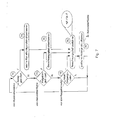
- Fig. 6 shows a schematic block diagram for the sequence of the method for determining a room acoustic impulse response in the time domain in authenticity.
- an acoustic input signal is emitted in a step 601 into the acoustic space to be examined.
- an acoustic output signal is measured in a step 602 by means of the acoustic measuring device.
- the acoustic output signals are evaluated in step 604 using a mathematical deconvolution process in the evaluation device in order to determine in real time the room acoustic impulse response in the time domain.
- the determined room acoustic impulse response is provided in step 605 for real-time output, for example output via a display. Even during the continued broadcast of acoustic input signals and the acquisition of acoustic output signals, results for the room acoustic impulse response are provided for the space under study.
- Fig. 7 shows a schematic block diagram for explaining a calculation module.
- an input-output module continuously receives incoming data for the detected acoustic output signals from the AD converter 17 (see FIG. Fig. 2 to 5 above) into a local circular data buffer or data to be output for the input acoustic signals to the DA converter 13 for processing in an analogous manner.
- the input-output module works in its own, independently defined process, which is also referred to as a thread, parallel to the other measurement and evaluation program.
- threads serving, for example, the calculation or representation of the room acoustic impulse response are notified, which will be explained in more detail below.
- Fig. 7 illustrates the operation of the calculation module.
- the calculation module also runs in its own thread and can be instantiated several times, so that a parallel processing of multiple inputs with acoustic output signals can be done.
- user interface events are continuously evaluated and the data processed by the input-output module.
- the user may set or change a channel configuration 71 and / or calculation tasks 72. Then, internal data structures of a computational thread are updated 74 and a corresponding computation path is created 75. After each change or whenever new input data is available 73, the current computation path is executed 76 and a graphical display is updated 77, for example the room acoustic impulse response.
- Fig. 8 12 shows a schematic block diagram for explaining calculation paths in the method for determining a room acoustic impulse response in the time domain in real time. Possible results are shown that can be derived from the data stream based on the acoustic output signal. Furthermore, necessary calculation paths for the determination of the results are shown schematically.
- an associated path 808 ⁇ 809 ⁇ 810 ⁇ 811 ⁇ 812 ⁇ 813 ⁇ 817 ⁇ 820 is activated and the memory required therefor by the operating system requested, so allocated.
- the memory for unused paths is automatically released by the program.
- new data for the acoustic output signals are read from the input-output module 808 in accordance with a current configuration 809 and internal reference and signal buffers 810, 812 are updated. These are implemented as local data blocks, which overall have the length of the desired room acoustic impulse response.
- the length of the updated input data corresponds to the time span between successive executions of the calculation path. As a rule, these are fractions of a second, which is much shorter than the length of the room-acoustic impulse response.
- An instantaneous local signal / reference data block with the length of the room acoustic impulse response is referred to as 'frame' (cf. Fig. 9 ).
- Criteria are defined according to which a frame contains meaningful measurement data. For example, an average signal level over a certain period of time should exceed a certain threshold.
- a signal detector function 831 see also explanations on the automatic, pcg-controlled triggering below
- all frames which do not meet these criteria are discarded and the calculation is suspended until the next update. Otherwise, the buffers are optionally windowed and Fourier transformed to reference and signal spectra 811, 813. From this, corresponding power spectra 815, 816 are calculated.
- further signal or input channels 814 see also explanations on the use of several input channels below. averaging over all signal channels is additionally performed.
- a transfer function 817 as a central variable is calculated by means of complex division of the signal spectrum 813 by the reference spectrum 811 in the frequency domain.
- the connection of filters is possible in order to not allow for the measurement signal components that lie outside a frequency range to be measured.
- noise-level filters 830 are also used, greatly reducing a relative contribution of those frequencies below a certain relative level compared to the maximum level (Wiener Criterion). For this purpose, signal components of the acoustic output signals are effectively switched off, which are indeed in the permitted frequency range, but only noise. The user can enter pass limits. The corresponding filters are then applied to the transfer function 817.
- the amount 818 if necessary taking into account a power spectrum from a multi-channel averaging and phase 819, is calculated.
- An inverse Fourier transform of a transfer function 817 results in a spatial impulse response 820.
- band filtered transfer functions 821 are calculated by means of octave filters, then band filtered spatial impulse responses 823 via inverse Fourier transform.
- Band filtered 824 or broadband 829 or 824 broadband spatial impulse responses can then be derived from the band filtered spatial impulse response 823 ETCs (ETC - "Energy Time Curve", corresponds to the squared, logarithmically represented room acoustic impulse response) can be calculated. Hicraus are then determined to room acoustic parameters 826.
- a further improvement of the evaluation of the acoustic output signals for determining the room acoustic impulse response is to define a detection time window in the time domain for the analysis of the early arriving portions of the acoustic output signals (see also explanations below for the use of a detection time-lapse).
- the acquisition time window is set so that although a direct sound and first reflections input into the evaluation for the determination of the room acoustic impulse response, but not later reflections and disturbances.
- This method primarily serves to determine a frequency response which corresponds to the subjectively perceived tonal balance and also correlates in time length with the components of the room acoustic impulse response which are decisive for the directional location.
- the band-filtered room impulse response 823 or the broadband room impulse response 820 is windowed 822 and from this an associated windowed transfer function is calculated 825. Finally, from the windowed transfer function, the amount 827 and phase 828 can be determined and displayed.
- each represented result is calculated by averaging over all frames in a given period of time.
- the efficient Administration is, for example, by selecting and issuing calculation tasks according to the dependency tree in Fig. 8 achieved so that the calculations that are not on the path from the input signal to the desired result, are not executed or the necessary memory is not allozicrt. Thus, only a minimal amount of memory is ever allocated or the minimum number of operations per frame is executed.
- the deconvolution itself is adjusted so that missing spectral components (in this case, speech is strongly band-limited) are masked out of the calculation of the room acoustic impulse response.
- missing spectral components in this case, speech is strongly band-limited
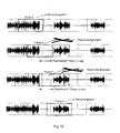
- Fig. 10 shows a schematic representation for explaining such an automatic, level-triggered triggering of a calculation of the room acoustic impulse response in an evaluation, whereby a temporary elimination of a calculation path is conditional. If the input power of the acoustic output signal falls below a certain threshold value over a certain period of time defined by the user (see Fig. 10 Frames 102 and 103), then the further calculation of the room acoustic impulse response is turned off by the time the noise portion of the respective frame becomes less than a user-defined threshold.
- the use of a multi-thread technology allows the use of independent computational threads or computational processes for a so-called stream buffering, the computation, graphical representations and the user interface.
- stream buffering the computation, graphical representations and the user interface.
- standard or user-defined processes to be processed can be detached from each other and performed efficiently.
- the multi-thread technology is supported hardware-close and thus allows considerable performance gains.
- this distribution makes the application very fast and, on the other hand, it remains interactive even at high loads and does not lose any data from the continuously running input and output.
- the parallelization of calculation and evaluation functions is not a trivial task. The possibilities are always heavily dependent on the structure of the processes to be processed and require exact adaptation and synchronization.
- multiple data streams such as overlays or in principle other Livc channels can then be processed and displayed in parallel on multiprocessor systems by creating a separate, fully functional Thrcad for each data stream.
- Fig. 11 shows a schematic diagram for explaining the use of multi-threaded technology.
- the interaction with the user occurs in a user interface thread 1131 where a measurement configuration and calculation options are selected by the user.
- one or more input-output threads 1132 are started that manage real-time interaction with input-output devices.
- Computation modules 1133 are also instantiated by the user interface thread 1131. They are notified by the input / output modules when there are new signals relating to the acoustic output signals. Their functionality was above in Fig. 7 explained in more detail.
- the computational results for a current frame are present, they are displayed in a display thread 1134.
- An embodiment of the method provides for the use of several input channels of the evaluation device at the same time (cf. Fig. 5 and related explanations above), for example, eight input channels.
- eight complex frequency responses can be averaged become. This allows, in contrast to known "one-place" measurements at the same time several places, for example, in different Hörcrzonen in the stadium, evaluate and thus gain a representative (global) overall frequency response. This is very important because an equalizer always works on a PA system as a whole and thus can only be used globally.
- with spatially uncorrelated noise and the signal-to-noise ratio can be increased by up to 9 dB (eight channels).
- Fig. 12 shows a schematic representation for explaining the running in real time calculation of the room acoustic impulse response in the time domain, taking into account several input channels of the evaluation (see also Fig. 5 ).
- Input data 1235 is assigned to a reference buffer 1237 or multi-channel buffers 1238 according to a channel configuration 1236. Each channel is fenestrated and Fourier transformed. Then, power spectra 1239 are averaged 1241. By dividing by the power spectrum of a reference channel 1240, an averaged amount of the transfer function TF 1242 is formed.
- the transfer function is the Fouric transform of the room acoustic impulse response.
- an analysis of early arriving portions of an original room acoustic impulse response is provided, which in turn is derived from the acoustic output signal.
- a collection time window has to be defined in the time domain.
- the acquisition time window is set so that although a direct sound and first reflections input into the evaluation, but not later reflections and disturbances.
- this measure serves to determine a frequency response that corresponds to a subjectively perceived, tonal balance and also correlates in time length with components of the room acoustic impulse response which are decisive for the directional location.
- a detection time window is also used whose time length changes with frequency, ie is significantly longer for low frequencies and shorter for high frequencies.
- the window function has about half the time length for a twice as high frequency.
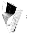
- the acquisition time window is preferably formed as a parameterized, functional form "window (time t, frequency f)", which represents a continuous acquisition time window in time-frequency space (cf. Fig. 13 ).
- the room acoustic impulse response is multiplied by an associated acquisition time window. Subsequently, the Fourier coefficient is calculated by means of single-point convergence transformation. As the window length decreases with higher frequency, the process can also be performed for larger time lengths of the room acoustic impulse response with high performance.
Landscapes
- Physics & Mathematics (AREA)
- Engineering & Computer Science (AREA)
- Acoustics & Sound (AREA)
- Signal Processing (AREA)
- General Physics & Mathematics (AREA)
- Measurement Of Mechanical Vibrations Or Ultrasonic Waves (AREA)
Applications Claiming Priority (1)
| Application Number | Priority Date | Filing Date | Title |
|---|---|---|---|
| DE102007031677A DE102007031677B4 (de) | 2007-07-06 | 2007-07-06 | Verfahren und Vorrichtung zum Ermitteln einer raumakustischen Impulsantwort in der Zeitdomäne |
Publications (2)
| Publication Number | Publication Date |
|---|---|
| EP2012558A2 true EP2012558A2 (fr) | 2009-01-07 |
| EP2012558A3 EP2012558A3 (fr) | 2009-09-02 |
Family
ID=40011042
Family Applications (1)
| Application Number | Title | Priority Date | Filing Date |
|---|---|---|---|
| EP08012163A Withdrawn EP2012558A3 (fr) | 2007-07-06 | 2008-07-04 | Procédé et dispositif destinés à déterminer une réaction d'impulsion acoustique dans le domaine temporel |
Country Status (3)
| Country | Link |
|---|---|
| US (1) | US8208647B2 (fr) |
| EP (1) | EP2012558A3 (fr) |
| DE (1) | DE102007031677B4 (fr) |
Cited By (2)
| Publication number | Priority date | Publication date | Assignee | Title |
|---|---|---|---|---|
| WO2011009504A1 (fr) * | 2009-07-21 | 2011-01-27 | Rohde & Schwarz Gmbh & Co. Kg | Dispositif de mesure sélectif en fréquence et procédé de mesure sélectif en fréquence |
| WO2013003092A1 (fr) * | 2011-06-29 | 2013-01-03 | Harman International Industries, Incorporated | Stimuli de mesure musicaux |
Families Citing this family (27)
| Publication number | Priority date | Publication date | Assignee | Title |
|---|---|---|---|---|
| EP2288184A1 (fr) | 2009-07-20 | 2011-02-23 | Nxp B.V. | Génération d'énergie acoustique |
| WO2011015932A1 (fr) * | 2009-08-03 | 2011-02-10 | Imax Corporation | Systèmes et procédés permettant de surveiller des haut-parleurs de cinéma et compenser les problèmes de qualité |
| JP5606234B2 (ja) * | 2010-09-13 | 2014-10-15 | キヤノン株式会社 | 音響装置 |
| WO2012048299A1 (fr) * | 2010-10-07 | 2012-04-12 | Clair Brothers Audio Enterprises, Inc. | Procédé et système pour améliorer le son |
| US9602916B2 (en) | 2012-11-02 | 2017-03-21 | Sony Corporation | Signal processing device, signal processing method, measurement method, and measurement device |
| US10175931B2 (en) * | 2012-11-02 | 2019-01-08 | Sony Corporation | Signal processing device and signal processing method |
| US20140180629A1 (en) * | 2012-12-22 | 2014-06-26 | Ecole Polytechnique Federale De Lausanne Epfl | Method and a system for determining the geometry and/or the localization of an object |
| JP6326071B2 (ja) | 2013-03-07 | 2018-05-16 | アップル インコーポレイテッド | 部屋およびプログラム反応型ラウドスピーカシステム |
| EP2997327B1 (fr) * | 2013-05-16 | 2016-12-07 | Koninklijke Philips N.V. | Dispositif et méthode de détermination d'une estimation de dimension d'une pièce |
| US10609475B2 (en) | 2014-12-05 | 2020-03-31 | Stages Llc | Active noise control and customized audio system |
| US9747367B2 (en) | 2014-12-05 | 2017-08-29 | Stages Llc | Communication system for establishing and providing preferred audio |
| US9508335B2 (en) | 2014-12-05 | 2016-11-29 | Stages Pcs, Llc | Active noise control and customized audio system |
| US9654868B2 (en) | 2014-12-05 | 2017-05-16 | Stages Llc | Multi-channel multi-domain source identification and tracking |
| US10375501B2 (en) | 2015-03-17 | 2019-08-06 | Universitat Zu Lubeck | Method and device for quickly determining location-dependent pulse responses in signal transmission from or into a spatial volume |
| GB201510032D0 (en) | 2015-06-09 | 2015-07-22 | Kp Acoustics Ltd | Integrated sensor system |
| JP6511355B2 (ja) * | 2015-07-08 | 2019-05-15 | クラリオン株式会社 | 報知装置および報知方法 |
| EP3148213B1 (fr) | 2015-09-25 | 2018-09-12 | Starkey Laboratories, Inc. | Estimation de fonction de transfert relatif dynamique utilisant un apprentissage bayésien rare structuré |
| FR3044509B1 (fr) * | 2015-11-26 | 2017-12-15 | Invoxia | Procede et dispositif pour estimer la reverberation acoustique |
| US10945080B2 (en) | 2016-11-18 | 2021-03-09 | Stages Llc | Audio analysis and processing system |
| US9980042B1 (en) | 2016-11-18 | 2018-05-22 | Stages Llc | Beamformer direction of arrival and orientation analysis system |
| US9980075B1 (en) | 2016-11-18 | 2018-05-22 | Stages Llc | Audio source spatialization relative to orientation sensor and output |
| JP7020432B2 (ja) | 2017-01-31 | 2022-02-16 | ソニーグループ株式会社 | 信号処理装置、信号処理方法及びコンピュータプログラム |
| US10524079B2 (en) | 2017-08-31 | 2019-12-31 | Apple Inc. | Directivity adjustment for reducing early reflections and comb filtering |
| EP4029018B1 (fr) * | 2019-09-11 | 2023-07-26 | DTS, Inc. | Amélioration de l'intelligibilité de la voix sensible au contexte |
| US11350232B1 (en) * | 2020-03-13 | 2022-05-31 | Facebook Technologies, Llc | Systems and methods for determining room impulse responses |
| DE102022131411A1 (de) * | 2022-11-28 | 2024-05-29 | D&B Audiotechnik Gmbh & Co. Kg | Verfahren, computerprogramm und vorrichtung zur simulation des zeitlichen verlaufs eines schalldrucks |
| DE102023118980A1 (de) | 2023-07-18 | 2025-01-23 | Audi Aktiengesellschaft | Automatische Schalloptimierung in einem Fahrzeuginnenraum in Echtzeit |
Citations (4)
| Publication number | Priority date | Publication date | Assignee | Title |
|---|---|---|---|---|
| US3718813A (en) | 1972-01-19 | 1973-02-27 | O Williams | Technique for correlation method of determining system impulse response |
| US4067060A (en) | 1976-07-06 | 1978-01-03 | Canadian Patents And Development Limited | Transfer function measurement |
| US20030036872A1 (en) | 2001-03-14 | 2003-02-20 | Stark Donald Wilson | Data acquisition instrument architecture with flexible data acquisition, processing and display |
| DE102004047042A1 (de) | 2004-09-28 | 2006-04-06 | Rohde & Schwarz Gmbh & Co Kg | Verfahren und Vorrichtung zur Spektrumanalyse eines Nutz- oder Rauschsignals |
Family Cites Families (7)
| Publication number | Priority date | Publication date | Assignee | Title |
|---|---|---|---|---|
| US5412731A (en) * | 1982-11-08 | 1995-05-02 | Desper Products, Inc. | Automatic stereophonic manipulation system and apparatus for image enhancement |
| NL8300671A (nl) * | 1983-02-23 | 1984-09-17 | Philips Nv | Automatisch egalisatiesysteem met dtf of fft. |
| DD242954A3 (de) * | 1983-12-14 | 1987-02-18 | Deutsche Post Rfz | Grossraumbeschallungssystem |
| US5594174A (en) | 1994-06-06 | 1997-01-14 | University Of Washington | System and method for measuring acoustic reflectance |
| US6111957A (en) * | 1998-07-02 | 2000-08-29 | Acoustic Technologies, Inc. | Apparatus and method for adjusting audio equipment in acoustic environments |
| WO2004097350A2 (fr) * | 2003-04-28 | 2004-11-11 | The Board Of Trustees Of The University Of Illinois | Estimation du volume d'une piece et estimation des dimensions d'une piece |
| US7296472B2 (en) * | 2004-02-03 | 2007-11-20 | University Of Denver | Method and apparatus for acoustic sensing of structures |
-
2007
- 2007-07-06 DE DE102007031677A patent/DE102007031677B4/de not_active Expired - Fee Related
-
2008
- 2008-07-04 EP EP08012163A patent/EP2012558A3/fr not_active Withdrawn
- 2008-07-05 US US12/168,112 patent/US8208647B2/en active Active
Patent Citations (4)
| Publication number | Priority date | Publication date | Assignee | Title |
|---|---|---|---|---|
| US3718813A (en) | 1972-01-19 | 1973-02-27 | O Williams | Technique for correlation method of determining system impulse response |
| US4067060A (en) | 1976-07-06 | 1978-01-03 | Canadian Patents And Development Limited | Transfer function measurement |
| US20030036872A1 (en) | 2001-03-14 | 2003-02-20 | Stark Donald Wilson | Data acquisition instrument architecture with flexible data acquisition, processing and display |
| DE102004047042A1 (de) | 2004-09-28 | 2006-04-06 | Rohde & Schwarz Gmbh & Co Kg | Verfahren und Vorrichtung zur Spektrumanalyse eines Nutz- oder Rauschsignals |
Non-Patent Citations (3)
| Title |
|---|
| AHNERT ET AL.: "Software based Live sound measurements", AES 121 ST CONVENTION, 8 October 2006 (2006-10-08), pages 1 - 12 |
| PAUL A. LYNN: "Introductory Digital Signal Processing with Computer Applications", 1 January 1994, JOHN WILEY & SONS, pages: 275 - 279 |
| PAUL A. LYNN: "Introductory Digital Signal Processing with Computer Applications", part 8.3.2 Signal Segmentation 1 January 1994, JOHN WILEY & SONS, England, ISBN: 0471976318, pages: 275 - 279 * |
Cited By (4)
| Publication number | Priority date | Publication date | Assignee | Title |
|---|---|---|---|---|
| WO2011009504A1 (fr) * | 2009-07-21 | 2011-01-27 | Rohde & Schwarz Gmbh & Co. Kg | Dispositif de mesure sélectif en fréquence et procédé de mesure sélectif en fréquence |
| US8964823B2 (en) | 2009-07-21 | 2015-02-24 | Rohde & Schwarz Gmbh & Co. Kg | Frequency selective measuring device and frequency selective measuring method |
| WO2013003092A1 (fr) * | 2011-06-29 | 2013-01-03 | Harman International Industries, Incorporated | Stimuli de mesure musicaux |
| US9060237B2 (en) | 2011-06-29 | 2015-06-16 | Harman International Industries, Incorporated | Musical measurement stimuli |
Also Published As
| Publication number | Publication date |
|---|---|
| DE102007031677B4 (de) | 2010-05-20 |
| US8208647B2 (en) | 2012-06-26 |
| US20090010443A1 (en) | 2009-01-08 |
| DE102007031677A1 (de) | 2009-01-15 |
| EP2012558A3 (fr) | 2009-09-02 |
Similar Documents
| Publication | Publication Date | Title |
|---|---|---|
| DE102007031677B4 (de) | Verfahren und Vorrichtung zum Ermitteln einer raumakustischen Impulsantwort in der Zeitdomäne | |
| AT410597B (de) | Verfahren, computersystem und computerprodukt zur messung akustischer raumeigenschaften | |
| EP1977626B1 (fr) | Procédé pour enregistrer et reproduire les signaux sonores d'une source sonore présentant des caractéristiques directives variables dans le temps | |
| EP1143416A2 (fr) | Suppression de bruit dans le domaine temporel | |
| DE60205232T2 (de) | Verfahren und vorrichtung zur bestimmung der qualität eines sprachsignals | |
| WO2002075725A1 (fr) | Procede et dispositif pour determiner un niveau de qualite d'un signal audio | |
| DE60311619T2 (de) | Datenreduktion in Audiokodierern unter Ausnutzung nichtharmonischer Effekte | |
| WO2017157519A1 (fr) | Procédé pour déterminer de manière automatique une fonction individuelle d'une carte de niveaux selon la méthode de mesure des produits de distorsion des émissions oto-acoustiques (pdeoa) de l'ouïe chez l'homme ou l'animal | |
| EP2070388A2 (fr) | Procédé et dispositif de mesure pour le contrôle de systèmes de sonorisation | |
| EP3454572A1 (fr) | Procédé de reconnaissance d'un défaut dans un appareil auditif | |
| EP3349483A1 (fr) | Procédé de fonctionnement d'un système auditif et système auditif | |
| EP2545717A1 (fr) | Suppression de la réverbération de signaux d'un dispositif auditif biauriculaire | |
| EP3638103A1 (fr) | Procédé et dispositif pour étudier l'audition | |
| DE102010041146A1 (de) | Verbesserung der Patientenkommunikation in einem MRT | |
| DE10318191A1 (de) | Verfahren zur Erzeugung und Verwendung einer Übertragungsfunktion | |
| DE19902317C1 (de) | Vorrichtung und Verfahren zur Qualitätsbeurteilung von mehrkanaligen Audiosignalen | |
| DE102014204665B4 (de) | Geräuschoptimierung einer Magnetresonanzanlage | |
| DE102012204193B4 (de) | Audioprozessor und Verfahren zum Verstärken oder Dämpfen eines empfangenen Audiosignals | |
| EP1401243B1 (fr) | Méthode pour l'optimisation d'un signal audio | |
| AT413973B (de) | Verfahren und einrichtung zur überwachung der zugvollständigkeit | |
| DE102018120229A1 (de) | Verfahren zur Auralisierung von Lautsprechern und Impulsantwort | |
| EP4365890A1 (fr) | Appareil et procédé de génération adaptative de sons de masquage vocaux harmoniques | |
| DE102014100642A1 (de) | Anordnung und Verfahren zur Erfassung von Signalen | |
| DE10361954B4 (de) | Hörsystem und Verfahren zur Einstellung eines solchen, Verfahren zur Erkennung von charakteristischen Schallspektren, sowie entsprechende Computerprogramme und entsprechende computerlesbare Speichermedien | |
| DE102017202372A1 (de) | Diagnose eines Audiosystems |
Legal Events
| Date | Code | Title | Description |
|---|---|---|---|
| PUAI | Public reference made under article 153(3) epc to a published international application that has entered the european phase |
Free format text: ORIGINAL CODE: 0009012 |
|
| AK | Designated contracting states |
Kind code of ref document: A2 Designated state(s): AT BE BG CH CY CZ DE DK EE ES FI FR GB GR HR HU IE IS IT LI LT LU LV MC MT NL NO PL PT RO SE SI SK TR |
|
| AX | Request for extension of the european patent |
Extension state: AL BA MK RS |
|
| PUAL | Search report despatched |
Free format text: ORIGINAL CODE: 0009013 |
|
| AK | Designated contracting states |
Kind code of ref document: A3 Designated state(s): AT BE BG CH CY CZ DE DK EE ES FI FR GB GR HR HU IE IS IT LI LT LU LV MC MT NL NO PL PT RO SE SI SK TR |
|
| AX | Request for extension of the european patent |
Extension state: AL BA MK RS |
|
| RIC1 | Information provided on ipc code assigned before grant |
Ipc: G01R 23/00 20060101ALI20090729BHEP Ipc: H04S 7/00 20060101AFI20081126BHEP Ipc: G01H 7/00 20060101ALI20090729BHEP |
|
| 17P | Request for examination filed |
Effective date: 20091007 |
|
| AKX | Designation fees paid |
Designated state(s): AT BE BG CH CY CZ DE DK EE ES FI FR GB GR HR HU IE IS IT LI LT LU LV MC MT NL NO PL PT RO SE SI SK TR |
|
| 17Q | First examination report despatched |
Effective date: 20100512 |
|
| STAA | Information on the status of an ep patent application or granted ep patent |
Free format text: STATUS: THE APPLICATION IS DEEMED TO BE WITHDRAWN |
|
| 18D | Application deemed to be withdrawn |
Effective date: 20180201 |