EP2012576A2 - Automate d'implantation et procédé de manipulation de composants - Google Patents
Automate d'implantation et procédé de manipulation de composants Download PDFInfo
- Publication number
- EP2012576A2 EP2012576A2 EP08104405A EP08104405A EP2012576A2 EP 2012576 A2 EP2012576 A2 EP 2012576A2 EP 08104405 A EP08104405 A EP 08104405A EP 08104405 A EP08104405 A EP 08104405A EP 2012576 A2 EP2012576 A2 EP 2012576A2
- Authority
- EP
- European Patent Office
- Prior art keywords
- components
- placement
- handling
- holding means
- axis
- Prior art date
- Legal status (The legal status is an assumption and is not a legal conclusion. Google has not performed a legal analysis and makes no representation as to the accuracy of the status listed.)
- Granted
Links
- 238000000034 method Methods 0.000 title claims abstract description 31
- 239000000758 substrate Substances 0.000 claims abstract description 43
- 238000012795 verification Methods 0.000 claims description 9
- 238000000151 deposition Methods 0.000 claims 1
- 238000012937 correction Methods 0.000 description 4
- 230000001419 dependent effect Effects 0.000 description 1
- 238000001514 detection method Methods 0.000 description 1
- 238000006073 displacement reaction Methods 0.000 description 1
- 230000008092 positive effect Effects 0.000 description 1
- 238000012552 review Methods 0.000 description 1
- 238000012546 transfer Methods 0.000 description 1
Images

Classifications
-
- H—ELECTRICITY
- H05—ELECTRIC TECHNIQUES NOT OTHERWISE PROVIDED FOR
- H05K—PRINTED CIRCUITS; CASINGS OR CONSTRUCTIONAL DETAILS OF ELECTRIC APPARATUS; MANUFACTURE OF ASSEMBLAGES OF ELECTRICAL COMPONENTS
- H05K13/00—Apparatus or processes specially adapted for manufacturing or adjusting assemblages of electric components
- H05K13/04—Mounting of components, e.g. of leadless components
- H05K13/0404—Pick-and-place heads or apparatus, e.g. with jaws
- H05K13/0408—Incorporating a pick-up tool
- H05K13/041—Incorporating a pick-up tool having multiple pick-up tools
-
- H—ELECTRICITY
- H05—ELECTRIC TECHNIQUES NOT OTHERWISE PROVIDED FOR
- H05K—PRINTED CIRCUITS; CASINGS OR CONSTRUCTIONAL DETAILS OF ELECTRIC APPARATUS; MANUFACTURE OF ASSEMBLAGES OF ELECTRICAL COMPONENTS
- H05K13/00—Apparatus or processes specially adapted for manufacturing or adjusting assemblages of electric components
- H05K13/04—Mounting of components, e.g. of leadless components
- H05K13/0404—Pick-and-place heads or apparatus, e.g. with jaws
- H05K13/0413—Pick-and-place heads or apparatus, e.g. with jaws with orientation of the component while holding it; Drive mechanisms for gripping tools, e.g. lifting, lowering or turning of gripping tools
Definitions
- the invention relates to a placement for loading substrates with components and a method for handling components.
- the components are provided by feeders arranged at the placement machine at defined collection positions. There, the components are picked up by a placement of the placement and transferred to a placement area, where they are positioned on the substrates. Empty substrates are fed to the placement area via a transport device, and finished substrates are transported out of the placement area via this transport device.
- placement heads are used, which allow a simultaneous settling of several components.
- a placement head which adjusts the relative position of a plurality of holding devices so that a plurality of components can be deposited on the substrate by means of a single settling process.
- the invention has for its object to provide a placement and a method for handling components, which are characterized by greater flexibility in the simultaneous discontinuation of the components on the substrate.
- the placement machine for equipping substrates with components according to claim 1 has a placement head, which has a base body which is rotatably mounted about an axis of rotation directed perpendicular to a substrate plane. Furthermore, the placement head has at least two handling devices, which are arranged on the base body and each have holding means for holding the components. Furthermore, the placement machine has a positioning device by means of the placement head is movable parallel to the substrate plane, wherein at least one of the handling devices has a pivot axis, so that by rotation of the at least one handling device about this pivot axis, the relative distance of the holding means is variable.
- the plane of the substrate is to be understood as the plane in which the surface of the substrate to be assembled is located.
- the distance of the components held by the holding means can be varied within a wide range, whereby a high flexibility in handling and positioning of the components is achieved.
- By superposition of the movement of the pivot axis with the axis of rotation and the gantry axes of the travel range of the gantry axes can be reduced at the same achievable positions, whereby the transfer time can be significantly reduced. This also reduces the necessary space. This leads to a smaller machine and consequently to a better ratio of placement power to space requirement.
- the at least one pivot axis is arranged parallel to the axis of rotation.
- the at least two handling devices on individual swing drives by means of which the respective handling device is rotatable about its respective pivot axis.
- the at least two handling devices further individual drives, by means of which the holding means are each about a z-axis, which is arranged parallel to the rotation axis, rotatable and slidable in the direction of this respective z-axis.
- the holding means can be moved individually in the z-direction and rotated by itself. This allows a greater flexibility for the use of the placement head than when using common rotary or z-drives. Furthermore, the time shares for positioning can also be reduced here.
- the main body of the placement is executed rotationally symmetrical to the axis of rotation.
- the handling devices are arranged in the edge regions of the base body.
- This constructive configuration achieves a high degree of flexibility. For example, it may be for achievement Be a placement position sufficient to move only the axis of rotation of the body and the pivot axes of handling equipment, but not the portal axes of the positioning, whereby an additional heat input into the portal can be avoided.
- a portal movement is required due to the greater distance between two placement positions, then the movements of the independent axes (rotary and pivot axes or portal axes) can be superimposed. From this, a higher relative speed of the component and thus a shorter Bacpositionierzeit can be achieved, which mainly affects the real performance of the placement machine.
- a method for handling components for a placement machine according to claim 1 is claimed, wherein the distance of the holding means is adjusted by rotation of the handling means about the respective pivot axis such that a plurality of components can be handled simultaneously.
- Simultaneous handling of several components is possible, for example, when the placement head is in the region of the pick-up position, the placement position or the checking position and carries out the process steps to be executed there - such as picking up, loading or position detection - for several components simultaneously.
- the process steps can be significantly reduced, which directly affects the real performance of the placement machine.
- the components are provided at pick-up positions on the placement machine.
- the spacing of the holding means is adjusted so that a plurality of components can be picked up simultaneously from their pickup positions by the holding means.
- each component a placement position on the substrate is clearly assigned. Further, the distance of the holding means is adjusted so that a plurality of held by the holding means components can be deposited simultaneously on the substrate.
- main process times can also be parallelized during assembly, so that the overall process time for the placement can be significantly reduced, which in turn has a positive effect on the real performance of the placement machine.
- the placement head is moved after setting the distance of the holding means and before settling of the components on the substrate to a verification device for checking the position of the recorded components.
- the placement head is moved to a checking device for checking the position of the recorded components prior to settling of the components on the substrate. Furthermore, before the verification process, the handling equipment rotated about their pivot axes, that the relative distance of the recorded components is reduced.
- the relative distance of the components from one another can be reduced in such a way that the area enclosed by an envelope around all the components is reduced in a vertical projection onto the substrate plane.
- the space provided for the checking device can be significantly reduced.
- significantly cheaper checking devices can be used.
- FIG. 1 schematically shows a placement machine 1 for equipping substrates 2 with components 3.
- the placement machine consists of a cross member 7, which extends in a y-direction and fixed to a machine frame (not shown) is connected.
- a portal arm 8 is mounted, which extends in the x direction and is slidably mounted in the y direction on the cross member 7.
- Cross member 7 and portal arm 8 together form the positioning device, wherein by the x-axis and the y-axis orthogonal Reference system is formed.
- a placement head 6 is slidably mounted in the x direction, which via a plurality of handling devices 22 (see FIG. 2 ).
- a transport path 4 is provided for transporting the substrates 2 in a placement area.
- the substrates 2 are transported via the transport path 4 into the placement area of the placement machine 1.
- the components 3 provided by the feed devices 5 in the pick-up area are picked up by the placement head 6 and transferred in the direction of the placement area.
- the checking device 31 is approached so that the components 3 entrained by the placement head 6 can be checked with regard to their position and orientation. Subsequently, the components 3 are positioned on the substrate 2.
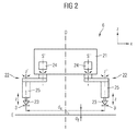
- FIG. 2 an embodiment of the placement head 6 is shown schematically in a side view.
- the placement head 6 has a base body 21, which is rotatably mounted about a rotation axis D, which is oriented orthogonal to the substrate plane E.
- Handling devices 22 are arranged on the base body 21, each of which has a single pivot drive 24 with which it can be eccentrically deflected about its respective pivot axis S 'or S "
- mechanical grippers as holding means 23.
- Both the pivot axes S 'and S “of the handling devices 22 and the axis of rotation D of the main body 21 are oriented parallel to the z-direction, so that a held component 3 both upon rotation about the axis of rotation D and about the pivot axis S' and S "or is always moved about its own axis of rotation z 'or z" of the holding means 23 in a plane parallel to the substrate plane E.
- a movement in the z-direction is not possible as a result of the positioning device 7, 8 (see FIG.
- the placement head 6 is movable in a plane parallel to the substrate plane E, the transported components 3 are always at the same distance d z to the substrate plane both in the rotational movements of the placement 6 and in the traversing movements of the positioning device 7 E.
- the change of this distance d z is carried out with the aid of each holding means 23 associated with individual drive 25, which also allows a displacement of the holding means in the z-direction.
- FIG. 2 only two handling devices 22 are shown. However, it is also possible to arrange further handling devices 22 on the main body 21 of the placement head 6.
- the method can be started by moving the placement head 6 into the pick-up area of the placement machine 1 becomes.
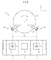
- FIG. 3 shows the placement head 6 in a plan view in the pick-up area before receiving the components.
- the two handling devices 22 are positioned relative to one another such that two associated components 3 can be picked up simultaneously. This is done by rotation of the handling devices 22 about their associated pivot axes S 'and S "and by rotation of the placement head 6 about the rotation axis D.
- the relative distance of the holding means 23 in the x and y direction corresponds to the relative distance of the components to be accommodated 3
- the two holding means 23 are aligned in the x-direction parallel to the pick-up windows 10.
- the placement head 6 is moved in the x-y direction by means of the positioning device 7, 8 such that the two holding means 23 are located directly above the two components 3 to be picked up.
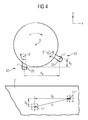
- FIG. 4 shows the placement head 6 in the placement area before settling of the components 3 on the substrate 2.
- each component 3 is assigned a placement position 11 on the substrate 2.
- the two handling devices 22 are positioned relative to one another in such a way that the two components 3 held by the holding means 23 can be deposited simultaneously on the substrate 2. This is done in turn by rotation of the handling devices 22 about their associated pivot axes S 'and S "and by rotation of the placement 6 around the rotation axis D.
- the relative distance of the holding means 23 corresponds to the relative distance d of the placement positions 11 'and 11 ", ie the spacing of the holding means 23 in the x and y directions (d x and d y ) the distance d x or d y of the placement positions 11 'and 11 "in the x and y direction, so that only one method of the mounting head to achieve the final settling position, from which only one feed movement in the z-direction 6 in the xy direction is required.
- the placement head 6 is moved in the x-y direction by means of the positioning device 7, 8 such that the two holding means 23 are located directly above the two placement positions 11 'and 11 ".
- the setting of the relative end position of the handling devices 22 is performed after the checking operation. This opens up the possibility of checking the pivot axes S 'and S "such that the held components 3 are arranged as close as possible and close to one another As a result of the reduction of the area required for checking the component position, a more compact and thus significantly more cost-effective checking device 31 can be used.
- the process time can be significantly reduced, so that a higher placement performance of the placement machine 1 can be realized.
Landscapes
- Engineering & Computer Science (AREA)
- Manufacturing & Machinery (AREA)
- Microelectronics & Electronic Packaging (AREA)
- Supply And Installment Of Electrical Components (AREA)
- Automatic Assembly (AREA)
- Specific Conveyance Elements (AREA)
Applications Claiming Priority (1)
| Application Number | Priority Date | Filing Date | Title |
|---|---|---|---|
| DE102007031487 | 2007-07-06 |
Publications (3)
| Publication Number | Publication Date |
|---|---|
| EP2012576A2 true EP2012576A2 (fr) | 2009-01-07 |
| EP2012576A3 EP2012576A3 (fr) | 2011-04-27 |
| EP2012576B1 EP2012576B1 (fr) | 2014-11-19 |
Family
ID=39789986
Family Applications (1)
| Application Number | Title | Priority Date | Filing Date |
|---|---|---|---|
| EP08104405.9A Ceased EP2012576B1 (fr) | 2007-07-06 | 2008-06-13 | Automate d'implantation et procédé de manipulation de composants |
Country Status (3)
| Country | Link |
|---|---|
| EP (1) | EP2012576B1 (fr) |
| JP (1) | JP5091031B2 (fr) |
| CN (1) | CN101340809B (fr) |
Cited By (2)
| Publication number | Priority date | Publication date | Assignee | Title |
|---|---|---|---|---|
| EP3211983A4 (fr) * | 2014-10-20 | 2018-05-30 | Fuji Machine Mfg. Co., Ltd. | Système et procédé de correction de position d'adsorption d'élément pour machine de montage d'éléments du type à tête rotative |
| EP3833174A1 (fr) * | 2019-12-06 | 2021-06-09 | Mycronic AB | Outil de montage pour une machine de montage de composants |
Families Citing this family (3)
| Publication number | Priority date | Publication date | Assignee | Title |
|---|---|---|---|---|
| JP6263413B2 (ja) * | 2014-02-21 | 2018-01-17 | ヤマハ発動機株式会社 | 電子部品装着装置 |
| DE102014103373B4 (de) * | 2014-03-12 | 2021-11-18 | Asm Assembly Systems Gmbh & Co. Kg | Bestückkopf mit zwei relativ zu einem Schaft beweglichen Gruppen von Pinolen, Bestückautomat und Verfahren zum Bestücken |
| JP6818028B2 (ja) * | 2016-07-13 | 2021-01-20 | 株式会社Fuji | 部品実装機 |
Citations (1)
| Publication number | Priority date | Publication date | Assignee | Title |
|---|---|---|---|---|
| DE10202290A1 (de) | 2002-01-22 | 2003-07-31 | Siemens Ag | Bestückkopf und Bestückverfahren zum Bestücken von Substraten mit Bauelementen |
Family Cites Families (5)
| Publication number | Priority date | Publication date | Assignee | Title |
|---|---|---|---|---|
| JPS60171799A (ja) * | 1984-02-17 | 1985-09-05 | 松下電器産業株式会社 | 電子部品自動装着装置 |
| JPH0645787A (ja) * | 1992-07-23 | 1994-02-18 | Matsushita Electric Ind Co Ltd | 部品実装装置および部品実装方法 |
| JP2000323895A (ja) * | 1999-05-10 | 2000-11-24 | Popman:Kk | 電子部品自動装着装置 |
| JP4504157B2 (ja) * | 2004-10-29 | 2010-07-14 | 株式会社日立ハイテクインスツルメンツ | 電子部品装着装置の装着ヘッド |
| DE102008019100B3 (de) * | 2008-04-16 | 2009-08-13 | Siemens Aktiengesellschaft | Bestückkopf, Bestückautomat, Verfahren zum Abholen von Bauelementen sowie Verfahren zum Bestücken von Substraten |
-
2008
- 2008-06-13 EP EP08104405.9A patent/EP2012576B1/fr not_active Ceased
- 2008-07-01 JP JP2008172345A patent/JP5091031B2/ja not_active Expired - Fee Related
- 2008-07-04 CN CN2008101330291A patent/CN101340809B/zh not_active Expired - Fee Related
Patent Citations (1)
| Publication number | Priority date | Publication date | Assignee | Title |
|---|---|---|---|---|
| DE10202290A1 (de) | 2002-01-22 | 2003-07-31 | Siemens Ag | Bestückkopf und Bestückverfahren zum Bestücken von Substraten mit Bauelementen |
Cited By (7)
| Publication number | Priority date | Publication date | Assignee | Title |
|---|---|---|---|---|
| EP3211983A4 (fr) * | 2014-10-20 | 2018-05-30 | Fuji Machine Mfg. Co., Ltd. | Système et procédé de correction de position d'adsorption d'élément pour machine de montage d'éléments du type à tête rotative |
| US10531601B2 (en) | 2014-10-20 | 2020-01-07 | Fuji Corporation | Component pickup position correction system and component pickup position correction method for a rotary head type component mounter |
| EP3833174A1 (fr) * | 2019-12-06 | 2021-06-09 | Mycronic AB | Outil de montage pour une machine de montage de composants |
| WO2021110953A1 (fr) * | 2019-12-06 | 2021-06-10 | Mycronic AB | Outil de montage pour une machine de montage de composants |
| CN114731779A (zh) * | 2019-12-06 | 2022-07-08 | 迈康尼股份公司 | 用于元件安装机的安装工具 |
| CN114731779B (zh) * | 2019-12-06 | 2024-07-09 | 迈康尼股份公司 | 用于元件安装机的安装工具 |
| US12453068B2 (en) | 2019-12-06 | 2025-10-21 | Mycronic AB | Mounting tool for a component mounting machine |
Also Published As
| Publication number | Publication date |
|---|---|
| EP2012576B1 (fr) | 2014-11-19 |
| CN101340809B (zh) | 2012-07-18 |
| JP5091031B2 (ja) | 2012-12-05 |
| EP2012576A3 (fr) | 2011-04-27 |
| JP2009016834A (ja) | 2009-01-22 |
| CN101340809A (zh) | 2009-01-07 |
Similar Documents
| Publication | Publication Date | Title |
|---|---|---|
| EP1935223B1 (fr) | Procédé d'implantation de composants électriques sur un substrat et automate d'implantation | |
| EP2111092B1 (fr) | Tête à implanter, automate d'implantation, procédé destiné à aller chercher des composants et procédé destiné à implanter des substrats | |
| EP2190604A1 (fr) | Dispositif et procédé de positionnement de pièces en forme de plaques | |
| EP2012576B1 (fr) | Automate d'implantation et procédé de manipulation de composants | |
| WO2005087451A1 (fr) | Procede pour positionner des composants avec exactitude, et dispositif de positionnement correspondant | |
| EP2073620A1 (fr) | Dispositif de transport de substrat pour un automate d'implantation | |
| DE102008013753A1 (de) | Probenverschiebungsverfahren in Ladungsteilchenstrahlgerät und Ladungsteilchenstrahlgerät sowie Probe für Transmissionselektronenmikroskop | |
| EP2111091B1 (fr) | Agencement de transport de substrats, agencement de manipulation de substrats, agencement de fabrication de composants électroniques ainsi que procédé de manipulation de substrats | |
| DE102015113396B4 (de) | Bestückautomat, Handhabungssystem und Bestücksystem mit einem an einem Bestückautomaten lösbar angebrachten Handhabungssystem | |
| DE102008019101B4 (de) | Verfahren zum Bestücken von Substraten und Bestückautomat | |
| DE2007266A1 (de) | Einrichtung zum Befestigen von drahtförmigen Teilen auf einem Trägerteil mittels ültraschallschweißung | |
| DE20116653U1 (de) | Montageautomat für die Plazierung eines Halbleiterchips als Flipchip auf einem Substrat | |
| DE10031933A1 (de) | Bauteilmontagevorrichtung und Montageverfahren | |
| DE102020108037B4 (de) | Positionierungseinrichtung und Verfahren zur Positionierung von Werkstücken | |
| EP1954115B1 (fr) | Tête à implanter multiple dotée d'un entraînement rotatif collectif et d'un entraînement d'élévation mobile pour dispositifs de retenue de composants | |
| EP2140746A1 (fr) | Automate de placement de composants et procédé pour placer des composants sur des substrats | |
| EP1868238A2 (fr) | Dispositif de serrage pour une tranche de silicium | |
| DE102008035425B3 (de) | Bestückautomat zum Bestücken von Substraten mit Bauteilen | |
| EP1330152B1 (fr) | Tête de pose et procédé de pose de composants sur des substrats | |
| EP1941536B1 (fr) | Procédé et dispositif pour la pose d' éléments électroniques, en particulier des puces semi-conductrices, sur un substrat | |
| DE102021130295A1 (de) | Vorrichtung und Verfahren zur Herstellung von Solarmodulen | |
| DE102005033979B4 (de) | Bestücksystem und Verfahren zum Bestücken von Substraten mit elektrischen Bauteilen | |
| DE102005013283B4 (de) | Bestückautomat zum Bestücken von Substraten mit elektrischen Bauelementen | |
| EP1417874A1 (fr) | Procede et dispositif pour modifier la position de composants electroniques | |
| DE102008023614B3 (de) | Verfahren zum automatischen Positionieren von Unterstützungsstiften und Bestückautomat |
Legal Events
| Date | Code | Title | Description |
|---|---|---|---|
| PUAI | Public reference made under article 153(3) epc to a published international application that has entered the european phase |
Free format text: ORIGINAL CODE: 0009012 |
|
| AK | Designated contracting states |
Kind code of ref document: A2 Designated state(s): AT BE BG CH CY CZ DE DK EE ES FI FR GB GR HR HU IE IS IT LI LT LU LV MC MT NL NO PL PT RO SE SI SK TR |
|
| AX | Request for extension of the european patent |
Extension state: AL BA MK RS |
|
| RAP1 | Party data changed (applicant data changed or rights of an application transferred) |
Owner name: SIEMENS ELECTRONICS ASSEMBLY SYSTEMS GMBH & CO. KG |
|
| PUAL | Search report despatched |
Free format text: ORIGINAL CODE: 0009013 |
|
| RAP1 | Party data changed (applicant data changed or rights of an application transferred) |
Owner name: ASM ASSEMBLY SYSTEMS GMBH & CO. KG |
|
| AK | Designated contracting states |
Kind code of ref document: A3 Designated state(s): AT BE BG CH CY CZ DE DK EE ES FI FR GB GR HR HU IE IS IT LI LT LU LV MC MT NL NO PL PT RO SE SI SK TR |
|
| AX | Request for extension of the european patent |
Extension state: AL BA MK RS |
|
| 17P | Request for examination filed |
Effective date: 20111027 |
|
| AKX | Designation fees paid |
Designated state(s): AT BE BG CH CY CZ DE DK EE ES FI FR GB GR HR HU IE IS IT LI LT LU LV MC MT NL NO PL PT RO SE SI SK TR |
|
| RBV | Designated contracting states (corrected) |
Designated state(s): DE |
|
| GRAP | Despatch of communication of intention to grant a patent |
Free format text: ORIGINAL CODE: EPIDOSNIGR1 |
|
| INTG | Intention to grant announced |
Effective date: 20140620 |
|
| GRAS | Grant fee paid |
Free format text: ORIGINAL CODE: EPIDOSNIGR3 |
|
| GRAA | (expected) grant |
Free format text: ORIGINAL CODE: 0009210 |
|
| AK | Designated contracting states |
Kind code of ref document: B1 Designated state(s): DE |
|
| REG | Reference to a national code |
Ref country code: DE Ref legal event code: R096 Ref document number: 502008012410 Country of ref document: DE Effective date: 20141224 |
|
| REG | Reference to a national code |
Ref country code: DE Ref legal event code: R097 Ref document number: 502008012410 Country of ref document: DE |
|
| PLBE | No opposition filed within time limit |
Free format text: ORIGINAL CODE: 0009261 |
|
| STAA | Information on the status of an ep patent application or granted ep patent |
Free format text: STATUS: NO OPPOSITION FILED WITHIN TIME LIMIT |
|
| 26N | No opposition filed |
Effective date: 20150820 |
|
| PGFP | Annual fee paid to national office [announced via postgrant information from national office to epo] |
Ref country code: DE Payment date: 20190619 Year of fee payment: 12 |
|
| REG | Reference to a national code |
Ref country code: DE Ref legal event code: R119 Ref document number: 502008012410 Country of ref document: DE |
|
| PG25 | Lapsed in a contracting state [announced via postgrant information from national office to epo] |
Ref country code: DE Free format text: LAPSE BECAUSE OF NON-PAYMENT OF DUE FEES Effective date: 20210101 |