EP2013027B1 - Tintenstrahldruckkopfbaugruppe und verfahren zur gasentfernung - Google Patents
Tintenstrahldruckkopfbaugruppe und verfahren zur gasentfernung Download PDFInfo
- Publication number
- EP2013027B1 EP2013027B1 EP07797148.9A EP07797148A EP2013027B1 EP 2013027 B1 EP2013027 B1 EP 2013027B1 EP 07797148 A EP07797148 A EP 07797148A EP 2013027 B1 EP2013027 B1 EP 2013027B1
- Authority
- EP
- European Patent Office
- Prior art keywords
- ink
- printhead
- ink supply
- printhead assembly
- compliant chamber
- Prior art date
- Legal status (The legal status is an assumption and is not a legal conclusion. Google has not performed a legal analysis and makes no representation as to the accuracy of the status listed.)
- Not-in-force
Links
- 238000000034 method Methods 0.000 title claims description 6
- 239000012530 fluid Substances 0.000 claims description 32
- 230000007246 mechanism Effects 0.000 claims description 30
- 230000033001 locomotion Effects 0.000 claims description 14
- 238000004891 communication Methods 0.000 claims description 13
- 230000008878 coupling Effects 0.000 claims description 10
- 238000010168 coupling process Methods 0.000 claims description 10
- 238000005859 coupling reaction Methods 0.000 claims description 10
- 238000011144 upstream manufacturing Methods 0.000 claims description 9
- 230000004888 barrier function Effects 0.000 claims description 8
- 238000009825 accumulation Methods 0.000 claims description 3
- 239000007788 liquid Substances 0.000 claims description 3
- 230000005484 gravity Effects 0.000 claims description 2
- 238000010304 firing Methods 0.000 description 10
- 230000008859 change Effects 0.000 description 9
- 230000007935 neutral effect Effects 0.000 description 9
- 230000004044 response Effects 0.000 description 8
- 230000006870 function Effects 0.000 description 3
- 238000005192 partition Methods 0.000 description 3
- 239000003086 colorant Substances 0.000 description 2
- 230000037452 priming Effects 0.000 description 2
- 238000007639 printing Methods 0.000 description 2
- 230000001105 regulatory effect Effects 0.000 description 2
- 239000007787 solid Substances 0.000 description 2
- 230000001133 acceleration Effects 0.000 description 1
- 230000009471 action Effects 0.000 description 1
- 239000011111 cardboard Substances 0.000 description 1
- 239000004744 fabric Substances 0.000 description 1
- 238000010348 incorporation Methods 0.000 description 1
- 230000013011 mating Effects 0.000 description 1
- 239000012528 membrane Substances 0.000 description 1
- 230000005499 meniscus Effects 0.000 description 1
- 239000002184 metal Substances 0.000 description 1
- 239000000203 mixture Substances 0.000 description 1
- 210000002445 nipple Anatomy 0.000 description 1
- 239000002674 ointment Substances 0.000 description 1
- 239000000123 paper Substances 0.000 description 1
- 230000002093 peripheral effect Effects 0.000 description 1
- 230000002572 peristaltic effect Effects 0.000 description 1
- 239000004033 plastic Substances 0.000 description 1
- 239000011148 porous material Substances 0.000 description 1
- 230000002250 progressing effect Effects 0.000 description 1
- 238000004064 recycling Methods 0.000 description 1
- XLYOFNOQVPJJNP-UHFFFAOYSA-N water Chemical compound O XLYOFNOQVPJJNP-UHFFFAOYSA-N 0.000 description 1
Images


Classifications
-
- B—PERFORMING OPERATIONS; TRANSPORTING
- B41—PRINTING; LINING MACHINES; TYPEWRITERS; STAMPS
- B41J—TYPEWRITERS; SELECTIVE PRINTING MECHANISMS, i.e. MECHANISMS PRINTING OTHERWISE THAN FROM A FORME; CORRECTION OF TYPOGRAPHICAL ERRORS
- B41J2/00—Typewriters or selective printing mechanisms characterised by the printing or marking process for which they are designed
- B41J2/005—Typewriters or selective printing mechanisms characterised by the printing or marking process for which they are designed characterised by bringing liquid or particles selectively into contact with a printing material
- B41J2/01—Ink jet
- B41J2/17—Ink jet characterised by ink handling
- B41J2/175—Ink supply systems ; Circuit parts therefor
- B41J2/17596—Ink pumps, ink valves
-
- B—PERFORMING OPERATIONS; TRANSPORTING
- B41—PRINTING; LINING MACHINES; TYPEWRITERS; STAMPS
- B41J—TYPEWRITERS; SELECTIVE PRINTING MECHANISMS, i.e. MECHANISMS PRINTING OTHERWISE THAN FROM A FORME; CORRECTION OF TYPOGRAPHICAL ERRORS
- B41J2/00—Typewriters or selective printing mechanisms characterised by the printing or marking process for which they are designed
- B41J2/005—Typewriters or selective printing mechanisms characterised by the printing or marking process for which they are designed characterised by bringing liquid or particles selectively into contact with a printing material
- B41J2/01—Ink jet
- B41J2/17—Ink jet characterised by ink handling
- B41J2/175—Ink supply systems ; Circuit parts therefor
- B41J2/17503—Ink cartridges
- B41J2/17513—Inner structure
-
- B—PERFORMING OPERATIONS; TRANSPORTING
- B41—PRINTING; LINING MACHINES; TYPEWRITERS; STAMPS
- B41J—TYPEWRITERS; SELECTIVE PRINTING MECHANISMS, i.e. MECHANISMS PRINTING OTHERWISE THAN FROM A FORME; CORRECTION OF TYPOGRAPHICAL ERRORS
- B41J2/00—Typewriters or selective printing mechanisms characterised by the printing or marking process for which they are designed
- B41J2/005—Typewriters or selective printing mechanisms characterised by the printing or marking process for which they are designed characterised by bringing liquid or particles selectively into contact with a printing material
- B41J2/01—Ink jet
- B41J2/17—Ink jet characterised by ink handling
- B41J2/175—Ink supply systems ; Circuit parts therefor
- B41J2/17503—Ink cartridges
- B41J2/17556—Means for regulating the pressure in the cartridge
Definitions
- Inkjet printers fire droplets of ink from the nozzles of a printhead assembly onto print media.
- the ink is provided to the printhead assembly from an ink supply.
- the pressure in the ink supply should be managed to control ink flow to the printhead assembly. For example, if the ink supply lacks a sufficient backpressure, ink may leak from the nozzles. Alternatively, if the backpressure in the ink supply is excessive, the nozzles may not fire properly. However, even with effective management of the backpressure, gas may accumulate in the printhead assembly. This accumulation may restrict the ability of the printhead assembly to receive ink and to deliver ink to media, thereby reducing print quality and the useful lifespan of the printhead assembly.
- United States patent publication US5812163A discloses an orifice plate. firing nozzle, a firing chamber and a firing film. The firing film is flexed to expel ink out of the firing chamber towards the nozzle.
- European patent application publication EP0855274 discloses an ink jet recording head connected to a buffer tank. The buffer tank includes an elastically deformable upper face for suppressing a rise of pressure.
- the present teachings provide a method and an apparatus, for managing ink and gas using a compliant printhead assembly.
- printhead assembly The printhead assembly is defined according to claim 1.
- the method of removing gas is defined in claim 7.
- the present teachings may offer substantial advantages over other printing systems, including better pressure control, improved air management, better print quality, longer printhead life, higher flow rates, and/or replaceable ink cartridges with more efficient ink use, among others.
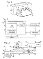
- Figure 1 shows an exemplary inkjet printer 20 with a compliant printhead assembly.
- the printer may include an ink management system 22 that stores ink in ink supplies 24, for example, replaceable cartridges 26.
- the ink management system also may supply ink to a printhead assembly 28 that delivers the ink to media 30 via the printhead assembly.
- the printer may be any type of apparatus capable of delivering ink (a liquid colorant) to media in a desired pattern.
- Exemplary printers that may be suitable include desktop printers, portable printers, large-format printers, plotters, photocopy machines, facsimile machines, multi-function peripherals, and/or the like.
- the printers may be suitable for printing on any suitable media, particularly sheet media.
- Exemplary media and/or media compositions that may be suitable include paper, cardboard, metal, plastic, wood, fabric, and/or the like.
- Fig. 2 shows printer 20 in more schematic form.
- the printer also may include a pump 36, one or more drivers 38, and a controlled 40.
- Pump 36 may be coupled to any suitable component(s) of the ink management system at any suitable position(s).
- the pump may be coupled to the ink supply, an upstream ink oasis, the printhead assembly, a position between the ink supply and the printhead assembly, and/or the like.
- the pump may be coupled continuously or at discrete times as needed to change the pressure within the ink management system.
- the pump may be coupled via a flexible conduit that allows relative movement of the pump and the coupled component.
- the pump may be coupled by bringing the pump into engagement with the coupled component, such as by bringing the ink supply to the pump in a service station of a printer (and/or by bringing the pump to the ink supply).
- the pump may exert a positive pressure, for example, by supplying a volume of fluid (gas (e.g., air) or liquid) to the management system, or may exert a negative pressure (a backpressure) by removing a volume of the fluid from the management system.
- the pump may be coupled upstream or downstream of any suitable component, to push or pull ink to or from the component.
- the pump may be of any suitable type, including bellows, double-diaphragm, flexible impeller, gear, linear, oscillating, peristaltic, piston (e.g., syringe pumps), progressing cavity, and/or rotary pumps, among others.
- Driver 38 may be one or more drive mechanisms that drive mechanical motion within the printer.
- Each drive mechanism may include a motor to provide a driving force.
- the drive mechanism may drive any suitable movement, such as movement of media relative to the ink management system, movement within the ink management system (e.g., relative movement within and/or between the pump, the ink supply, the printhead assembly, service station, etc.), and/or the like.
- Controller 40 may control any suitable components of the printer.
- the controller may control actuation/operation of each driver, the pump, and/or firing elements in the printhead assembly. Actuation and/or operation may be controlled according to time, frequency, direction, velocity, acceleration, and/or the like.
- the controller also may receive signals from various components of the printer to monitor operation of the components. For example, the controller may receive signals related to on/off state, position, velocity, volume, temperature, etc.
- the controller may include a processor, memory, a bus, input/output connections, processing instructions (e.g., hardware, firmware, and/or software), and/or the like.
- FIG. 3 shows ink management system 22 in somewhat schematic form.
- Ink 50 may be disposed in fluid compartments provided by ink supply 24 and printhead assembly 28.
- the ink supply may include an ink reservoir (a supply chamber) 52 disposed in fluid communication with a compliant chamber 54 of the printhead assembly.
- the ink reservoir may be substantially iarger in volume than the fluid capacity of the printhead assembly, for example, at least about ten-fold greater.
- the ink supply may be coupled permanently (i.e., configured not to be uncoupled by a user of the printer) or removably (i.e., configured to be uncoupled by a user for replacement, disposal, recycling, servicing, and/or re-filling the ink supply).
- the ink supply thus may be a modular cartridge including a housing 56 enclosing the ink reservoir.
- the ink supply and printhead assembly are coupled directly by coupling structures included in an outlet 58 of the ink supply housing and an inlet 60 of the printhead assembly.
- the ink supply and printhead assembly may be spaced by a discrete conduit(s) and/or intermediate ink vessei(s).
- ink supply 24 may include a backpressure or depressurization mechanism 62 to depressurize (to decrease the pressure of) the ink reservoir, such as to impart a backpressure (a net negative pressure relative to outside the ink supply) to the ink reservoir.
- the ink supply may include a pressurization mechanism 64 to increase the pressure of the ink reservoir, such as to impart a net positive pressure to the ink reservoir.
- the ink supply may includes one or more valves, such as valves 66, 68 to regulate and/or restrict communication between the ink reservoir and outside of the ink supply.
- Backpressure mechanism 62 may operate to pull on the ink in the ink reservoir.
- the backpressure mechanism may include a variable-volume (flexible) chamber 70 (generally an air chamber) and a biasing mechanism 72 that urges the flexible chamber to change its volume, generally urging the flexible chamber to contract to a smaller volume.
- the flexible chamber may be disposed in the ink supply, such as enclosed by housing 56 and having a flexible partition or membrane 74 that partitions the housing to form at least a portion of a wall of the flexible chamber. Changes in the volume of the flexible chamber may be permitted by an opening 76 in the supply housing.
- the biasing mechanism also may be disposed in the housing and may include a spring 78 or other biasing structure.
- Pressurization mechanism 64 may operate to push-prime the printer, by pushing gas out of the printhead assembly, particularly the printhead thereof.
- the pressurization mechanism also may use flexible chamber 70 or may use a distinct interface with the ink supply.
- the flexible chamber may be pressurized by pump 36 hermetically coupled to the flexible chamber.
- housing 56 may include a coupling structure, such as a nipple 80, a socket, a gasket, and/or the like, which may facilitate mating and/or restrict fluid leakage.
- the flexible chamber may be depressurized to or below atmospheric pressure by uncoupling the pump from the flexible chamber (such as by moving the pump relative to housing 56) and/or by releasing the pressure via a valve 82, among others.
- Valves 66, 68 may operate to control fluid communication through an opening or vent 84 of the housing, to determine whether or not fluid enters and/or exits the ink reservoir via the opening. Opening 84 may provide fluid communication between ink reservoir 52 and the ambient atmosphere outside the housing. Accordingly, the opening may control entry (or exit) of air/gas to (or from) the ink reservoir, such as when the ink supply is the upstream terminus (the initial source) of the ink. Alternatively, the opening may control entry (or exit) of ink to (or from) the ink reservoir.
- the ink reservoir may be coupled to an upstream ink oasis 86 (shown dashed as an optional component) that supplies ink to the ink reservoir through opening 84.
- an upstream ink oasis 86 shown dashed as an optional component
- the valves may have any suitable arrangement and structure.
- the valves may be coupled to the housing (e.g., both valves inside the housing, both valves outside the housing, and/or the valves disposed on opposing sides of the housing).
- one or more of the valves may be spaced from the housing, for example, upstream of the ink supply between the ink supply and an ink oasis and/or coupled to the ink oasis.
- the valves may be arranged in series to and/or in parallel.
- the valves, and particularly movable valve elements thereof may be formed by distinct components and/or by the same component(s).
- the valves may have valve seats formed by the same or distinct regions of the same component (e.g., valve seats that are overlapping or nonoverlapping), such as valve seats provided by the housing of the ink supply, and/or may have valve seats provided by distinct components.
- valves may be pressure sensitive. Furthermore, each valve may have a response pressure (a pressure at which the valve opens, closes, and/or adjusts flow rate) determined by fluid pressure alone and/or by a biasing structure, such as a lever and/or spring, among others.
- exemplary valves that may be suitable include angle, ball, bubble-generator (gap with a meniscus), butterfly, diaphragm, flapper, gate, globe, needle, pinch, slide, and/or stopcock valves.
- Printhead assembly 28 may form the downstream terminus of the ink management system from which ink exits the system. Accordingly, the printhead assembly includes a printhead 88 that is fed by compliant chamber 54.
- the printhead may include a plurality of nozzles 90 from which ink droplets 92 are fired onto media.
- the nozzles may be formed by an array of orifices 94 and associated firing elements 96, such as heater and/or piezoelectric elements, among others.
- Fig. 4-8 show an exemplary ink supply 110 for use in an inkjet printer with push priming.
- the ink supply is coupled (indicated at 112 in Fig. 4 ) to a downstream printhead assembly, and coupled (or couplable)(indicated at 114 in Fig. 4 ) to a pump.
- these additional components are omitted from the current views to simplify the presentation.
- the supply 110 has a housing 116 enclosing an ink reservoir 118 and an air chamber 120.
- the ink reservoir is disposed in fluid communication with the printhead assembly and adjoins the air chamber.
- Vent (opening) 122 of the housing provides fluid communication between the ink reservoir and outside the housing, for example, the ambient atmosphere in the present illustration.
- At least one valve 124 controls this fluid communication.
- the valve may be biased toward a closed position by a spring 126 or other biasing mechanism.
- the air chamber may be operatively and/or mechanically coupled to valve 124 via a lever 128.
- the air chamber may form part of a backpressure mechanism 130, and of a pressurization mechanism 132 (also see Fig. 3 ) that can be actuated to override the action of the backpressure mechanism.
- the air chamber may have any suitable structure and size.
- any suitable proportion of the walls of the air chamber may be flexible.
- at least substantially all of the wall structure of the air chamber may be flexible, to form a bag.
- approximately half or more of the wall structure (by area) may be relatively rigid, that is, resistant to substantial change in shape.
- an outer wall 134 and inner walls 136, 138 projecting inward from the outer wall form a substantial portion of the surface area of the air chamber.
- a flexible member, such as sheet 140 may be secured to the inner walls (spaced from the outer wall) to form the flexible portion of the air chamber.
- the flexible sheet may be secured adjacent, rather than spaced from, the outer wall.
- the flexible portion of the air chamber may be inelastic, that is, relatively resistant to an increase in surface area when the air chamber is under pressure, or may be elastic.
- the air chamber may include any suitable portion of a selected outer wall of the housing.
- the air chamber may include over at least about one-half of the surface area of the selected outer wall.
- the air chamber may be expandable, under normal operating conditions of the printer, to any suitable portion of the entire volume enclosed by the housing, such as at least about one-tenth, one-fifth, one-third, or one-half, among others.
- Fig. 4 shows ink supply 110 substantially full of ink.
- Air chamber 120 may be somewhat underinflated (i.e., deflated or contracted) and a spring 142 of the backpressure mechanism may be extended to create a backpressure, indicated by an arrow at 144, that urges ink in a direction toward the ink supply from the printhead assembly, to avoid leakage of ink out of the printhead orifices.
- valve 124 may be closed by spring 126 urging lever 128 against valve 124.
- Figs. 5 and 6 show ink supply 110 with ink reservoir 118 holding reduced volumes of ink relative to the configuration of Fig. 4 .
- air chamber 120 may be relatively expanded, indicated at 146 and 148, respectively, and spring 142 compressed more, indicated at 150 and 152, respectively.
- valve 124 may still be closed, indicated at 154 and 156, respectively, because lever 128 still maintains the valve in the closed position.
- the backpressure may be higher here than in Figure 4 , the backpressure may not be sufficiently high to restrict printhead operation substantially.
- Fig. 7 shows ink supply 110 with ink reservoir 118 holding a still further reduced volume of ink relative to the configurations of Figs. 4-6 .
- air chamber 120 may be expanded still further, indicated at 158, and spring 142 compressed still more, indicated at 160.
- lever 128 may be urged away, indicated at 162, from the valve by the position of the air chamber and/or a coupled structure such as spring 142.
- Valve 124 thus may open so that external air (or ink) can enter the ink reservoir via vent 122, to reduce the backpressure such that the backpressure is regulated within acceptable limits.
- Once sufficient air/ink is let into the ink reservoir the air chamber may return to a less expanded (less inflated) configuration, such as in any of Figs. 4-6 , and valve 124 should close.
- Fig. 8 shows ink supply 110 in a push-prime configuration in which the ink reservoir is pressurized.
- a pump may be actuated and/or coupled to the ink supply and a volume of gas (and/or fluid) introduced, indicated at 164, into the air chamber to expand/inflate the chamber additionally from the configuration of Fig. 7 .
- the net pressure in the ink reservoir may change from a backpressure to a positive pressure, indicated by the arrow at 166, which also may pressurize the printhead assembly.
- the additional expansion of the air chamber may urge lever 128 farther away from the valve, such that the valve is not biased toward a closed position by the lever.
- valve 124 also may operate as a check valve responsive to a net positive pressure in the ink reservoir and thus may close upon pressurization of the ink reservoir, to restrict flow of ink out of vent 122. Release of the positive pressure (for example by uncoupling from the pump) may allow the backpressure mechanism to deflate the air chamber and restore a backpressure (as in Figs. 4-7 ).
- the regulation ( Figs. 4-7 ) and check ( Fig. 8 ) functions of valve 124 may be performed by only one valve or by at least two valves disposed in series (e.g., see Figs. 12-18 ).
- Figs. 9-11 show an exemplary printhead assembly 180 for use in an inkjet printer with push priming.
- Printhead assembly 180 may be coupled to an ink supply 182 having a backpressure mechanism and also a pressurization mechanism that can be actuated selectively.
- the backpressure and pressurization mechanisms may function as described elsewhere in the present teachings (e.g., in relation to Figs. 4-8 ). However, these pressure control mechanisms (and most of the ink supply) are omitted from the present figures to simplify the presentation.
- Printhead assembly may include a body 184 and a printhead 186 connected to the body (see Fig. 4 ).
- the printhead may be mounted fixedly and/or nonremovably to the body.
- the printhead may be configured to be coupled to and uncoupled from the body, such as for printhead servicing or replacement.
- the printhead may be disposed in any position relative to the body.
- the printhead may be disposed generally adjacent the base (or top) of the body, for firing ink droplets downward (or upward) onto a horizontal medium surface.
- the printhead may be disposed to the side (laterally) of the body, for firing ink droplet Sideways onto a vertical medium surface.
- Body 184 may have a housing 188 including one or more fluid compartments that serve as a vessel for holding ink and/or gas.
- the body may include a compliant chamber 190 of variable volume.
- the compliant chamber may be formed in any suitable portion of the housing, may have any suitable volume, and may have any suitable range and direction of compliance.
- the compliant chamber is formed in a plenum region 192 above a filter 194 (e.g., for removing particulates from the ink as the ink moves through the body to the printhead) and above a standpipe region 196 between the filter and the printhead.
- the compliant chamber may be formed in the standpipe region.
- the compliant chamber may be configured to expand and contract, to hold a greater or lesser volume of fluid (ink and gas).
- the compliant chamber may be restricted in its ability to expand in response to a change from a neutral pressure (same inside and outside the chamber) to a positive pressure (greater inside than outside), relative to its ability to contract in response to a change from a neutral to a negative pressure (greater outside than inside).
- the compliant chamber may be restricted in its ability to contract in response to a change from a neutral pressure (same inside and outside the chamber) to a negative pressure (greater outside than inside). relative to its ability to expand in response to a change from a neutral to a positive pressure (greater inside than outside).
- the compliant chamber may have walls formed by the housing and/or by a compliant member 198.
- the compliant member may be, for example, a flexible member or sheet secured to the housing.
- the flexible member may be secured inside a wall of the housing, over a wall of the housing, and/or to cover an opening 200 of the housing.
- the movement of the flexible member may be restricted selectively in one of two opposing directions.
- body 184 may include a barrier or wall 202 disposed outward (or inward) of the flexible member. The barrier may restrict outward (or inward) movement of the flexible member selectively relative to inward (or outward) movement.
- barrier 202 may engage the flexible member to restrict outward movement of the barrier (and thus expansion of the compliant chamber)(see Fig. 10 ).
- the spacing between the barrier and the flexible member in the neutral configuration may determine the extent to which the flexible member can move outward in response to pressurization of the compliant chamber.
- the flexible member may move inward (e.g., to the concave configuration shown in Figs. 9 and 11 ) to contract the compliant chamber.
- One or more openings 204 in the barrier may allow air to move through the barrier as the flexible member moves inward and outward.
- the flexible member may be elastic or relatively inelastic.
- the flexible member may be planar under a neutral pressure condition.
- the flexible member may be elastic and nonplanar (e.g., flexed inward or outward) under a neutral pressure condition, to provide an asymmetric change in volume in response to positive and negative pressure changes.
- Body 184 also may include a ceiling compartment 206 for accumulation of gas, particularly air 208 (see Fig. 9 ).
- the ceiling compartment may be disposed adjacent a ceiling 209 within the body, below which gas may accumulate by gravity-driven movement. Accordingly, the ceiling compartment may be disposed in fluid communication with the compliant chamber and generally forms an upper region of the fluid compartment within body 184.
- the ceiling compartment may overlap partial or completely with the volume enclosed by the compliant chamber and/or may be nonoverlapping with the compliant chamber.
- Body 184 further may include an inlet 210 through which fluid may move between the ink supply and the fluid compartment of the printhead assembly.
- the inlet may provide a coupling structure 212 for connection of the printhead assembly to the ink supply.
- the inlet may define a channel 214 through which fluid may travel from the ink supply to the printhead assembly.
- the channel may adjoin the ceiling compartment and extend therefrom to the ink supply. Positioning the channel at about the same level as the ceiling compartment, such that the channel adjoins the ceiling compartment, may facilitate removal of gas (e.g., air) from the printhead assembly, as described below.
- the inlet further may include a gas-restrictive element 216 disposed in the channel.
- the gas-restrictive element may be an orifice element or needle, among others, with one or more orifices or pores small enough to restrict gas entry into the body. Restriction of gas entry may facilitate maintaining a backpressure in the printhead assembly if the assembly is disconnected from the ink supply, thereby restricting leakage of ink from the printhead.
- Fig. 9 shows the printhead assembly in a ready configuration for firing nozzles 218 of the printhead.
- Compliant chamber 190 may be in a relatively contracted configuration, with flexible member 198 pulled inward by a backpressure exerted on the compliant chamber by the backpressure mechanism of the ink supply.
- the extent to which the volume of the compliant chamber is reduced may be determined by the size of the backpressure, the size of the chamber and flexible member, the degree of flexibility and/or elasticity of the flexible member, and/or the like.
- Fig. 10 shows the printhead assembly with the ink supply pressurized by the pump.
- a volume of ink flows, indicated by an arrow at 220, through inlet channel 214 from an ink reservoir of the ink supply upstream, in response to the pressurization.
- a first portion of the volume of ink may expand the compliant chamber by pushing flexible member 198 outward, indicated at 222.
- a remaining second portion of the volume of ink may be urged out of the printhead. indicated by an arrow at 224 and producing external ink 226, to drive trapped gas out of the printhead and thus prime the printhead.
- the printhead may be wiped by a wiper 228 during and/or after pressurization of the printhead assembly.
- Wiping the printhead may help to prevent mixing of ink of different colors from nozzles connected to different ink compartments and/or to dislodge and remove gas bubbles that may otherwise be drawn back through the orifices by re-entry of ink from outside the printhead. (With a suction prime rather than a push-prime, the suction device may interfere with wiping.)
- the system may be configured such that any suitable proportion of the transferred ink volume drives expansion of the compliant chamber versus outflow from the printhead. in exemplary embodiments, the compliant chamber may expand by at least about one-tenth, one-fourth, or one-half the transferred volume.
- Fig. 11 shows the printhead assembly after the pressurization of the ink supply and printhead assembly has been discontinued.
- the backpressure mechanism in the ink supply may reduce the pressure in the ink reservoir of the ink supply such that pressure drops toward the ink reservoir from the printhead assembly. Accordingly, ink 230 and gas 232 may be urged out inlet channel 214 in a reverse flow, indicated by an arrow at 234, to the ink reservoir.
- Compliant chamber 190 may accommodate the reverse flow by contracting regionally, indicated at 236. Air that accumulates in upper portions of the printhead assembly by various mechanisms thus may be moved back to the ink supply so that the air doesn't interfere with operation of the printhead, overcoming the bubble pressure enforced by the gas-restrictive element.
- the bubble pressure may be about one to five inches.
- the air in the ink supply may be removed by displacing the air from the ink supply with ink (e.g., by re-filling the ink supply) and/or may be discarded along with the ink supply if the ink supply is replaced.
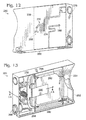
- FIGs. 12 and 13 show opposing sides of an exemplary ink cartridge 250 for use as an ink supply in a push-primed inkjet printer;
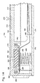
- FIG. 14 shows a sectional view taken through a portion of the cartridge.
- Cartridge, 250 may include a housing 252 forming the outer walls of the cartridge, including a light-transmissive outer wall 254 (a fragmentary portion is visible in Fig. 13 ) that permits the level of ink in the cartridge to be visible to a user from outside the cartridge.
- the housing may enclose an ink reservoir 256 and an air chamber 258 of variable volume.
- the ink reservoir and air chamber may share a common wall 260 formed by a flexible member that partitions the housing.
- the flexible member may be staked to an inner wall 262 of the housing (see Fig. 14 ).
- ink may exit the ink reservoir via a siphon tube 264 that extends from a base region of the ink reservoir to a coupling 266 of the housing (see Fig. 13 ).
- the coupling may be configured to be engaged with an inlet coupling of a printhead assembly to allow fluid to pass between the ink cartridge and the printhead assembly.
- Ink and/or gas also may enter the ink reservoir via the siphon tube from the printhead assembly and/or via an opening or vent 268 defined by the housing (see Figs. 12 and 14 ).
- a pair of valves that control access to opening 268 is described further below.
- Air chamber 258 may communicate with the ambient atmosphere and/or a pump via a vent 270 (see Figures 12 and 14 ).
- the vent may include a hole 272 defined by the housing and a surface channel 274 extending from the hole to a pump coupling 276.
- the surface channel may be formed by the exterior surface of the housing and a covering, such as film or tape 278 affixed to the exterior housing over the surface channel to enclose the surface channel.
- the surface channel may follow a tortuous path to provide a labyrinth that limits water vapor loss.
- the air chamber may form part of a backpressure mechanism (see Figs. 13 and 14 ).
- the backpressure mechanism may include a leaf spring 280 engaged with the flexible wall of the air chamber and with the housing. The leaf spring may urge the air chamber toward deflation.
- Fluid communication between ink reservoir 256 and opening 268 may be controlled by a pair of valves 282, 284 arranged in series (see Figs. 13 and 14 ).
- valve 282 may be a regulator valve.
- the regulator valve may include a movable valve element 286 that engages an outer valve seat 288 from by an interior surface of the housing's outer wall (see Figure 14 ).
- Regulator valve element 286 may be urged against valve seat 288 by a lever 290.
- the lever may be connected to the housing, operatively coupled to leaf spring 280 (and thus the air chamber), and biased by another spring 292. Expansion of the air chamber thus may urge the leaf spring against the lever to permit regulator valve element 286 to disengage the outer valve seat and thus allow external air to enter the ink reservoir, along a path indicated by a dashed arrow at 294 in Fig. 14 .
- Valve 284 may be a check valve disposed inward of regulator valve 282.
- Check valve 284 may include a check valve element 296 (e.g., a flap) that provides a flapper valve.
- the flapper valve (or at least a central portion of the valve) may be pre-loaded toward a closed position (engagement with an inner valve seat 298) by the spring.
- pressurization of the ink reservoir may cause check valve element 296 to continue to engage the inner valve seat formed by inner walls 300 of the housing disposed inward of and lateral to and/or around outer valve seat 288 for the regulator valve.
- Check valve element 296 may be flexible and/or more flexible than the regulator valve element. Accordingly, the perimeter region of the check valve element may respond to pressure differences, independent of the spring position, to engage the inner salve seat upon pressurization and to disengage with a backpressure.
- valves may be designed to be responsive to distinct pressure differences and thus may have a finer and/or more easily adjusted control of valve actuation, fluid movement, and pressure regulation.
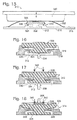
- Fig. 15 shows a sectional view of an exemplary ink cartridge 310 including a regulator valve 312 and a check valve 314 arranged in series.
- Valves 312 and 314 may be used in any suitable ink supply in place of a single valve and/or in place of the pair of valves described above (see Figs. 12-14 ).
- the valves may be coupled to a housing 316 of the cartridge enclosing an ink reservoir 318 and an air chamber 320.
- the valves may control communication between the ink reservoir and an opening 322 that communicates with outside the housing.
- Valves 312 and 314 may have respective valves elements 324. 326 formed by a shared valve body 328.
- the valve body may extend through opening 322, such that valve, elements 324 and 326 are disposed adjacent opposing sides of the opening.
- the valve body may be unitary or formed of two or more attached pieces.
- the valve body may be operatively coupled to the air chamber such that the valve body is urged outward by sufficient expansion of the air chamber.
- the valve body may be positioned to be engaged by a leaf spring 332 (urging deflation) if the air chamber becomes sufficiently inflated.
- Figure 16 shows a configuration of valve body 328 produced with a backpressure below a threshold backpressure for opening regulator valve 312.
- the valve body may be urged inward by a backpressure, indicated by an open arrow at 334, such that valve element 324 engages an outer valve seat 336 to close the valve and block flow of fluid between the outside and inside of the ink reservoir.
- Air chamber 320 may not be expanded sufficiently at this backpressure for the leaf spring to be pushed against the valve body.
- Figure 17 shows a configuration of valve body 328 produced with a backpressure at or above a threshold backpressure for opening regulator valve 312.
- the valve body may be urged inward by an increased backpressure, indicated by an open arrow at 338.
- air chamber 320 may be expanded sufficiently to push leaf spring 332 (see Fig. 15 ) against the valve body, indicated by solid arrows at 340 in Fig. 17 .
- the valve element 324 thus disengages outer valve seat 336 to open the valve and permit flow of fluid (e.g., ink or air) into the ink reservoir, indicated by a dashed arrow at 342.
- fluid e.g., ink or air
- Figure 18 shows a configuration of valve body 328 produced by pressurization of the ink reservoir.
- Valve element 324 may be urged toward the open position by engagement of leaf spring 332 against the valve body, indicated by solid arrows at 340.
- a positive pressure in the ink reservoir relative to outside the housing indicated by an outwardly directed open arrow at 344, may deform valve body 328 such that check valve element 326 engages an inner valve seat 346, to close the valve.
Landscapes
- Ink Jet (AREA)
Claims (8)
- Druckerkopfbausatz (180) zur Tintenabgabe von einem Tintenstrahldrucker (20), umfassend:einen Druckerkopf (188); einen Filter (194) zum Entfernen von Schwebstoffteilchen aus der Tinte, während sich die Tinte zum Druckerkopf (188) hin bewegt; undeinen Körper (184), der mit dem Druckerkopf (188) verbunden ist und dazu konfiguriert ist, Tinte (50) aus einer stromaufwärts verbundenen Tintenversorgung (182) zur Abgabe vom Druckerkopf (186),wobei der Körper (184) Folgendes umfasst:eine nachgiebige Kammer (190) über dem Filter (194) zum Beibehalten eines variablen Volumens an Tinte (50),ein Deckenabteil (206), das in Flüssigkeitsverbindung mit der nachgiebigen Kammer (190) steht und während des Gebrauchs zur schwerkraftgetriebenen Ansammlung von Gas (208) positioniert ist, undeinen Einlass (210), der während dem Gebrauch dazu konfiguriert ist, Tinte für den Körper (184) von der Tinthenversorgung (182) aufzunehmen, und eine Gegenströmung einer Flüssigkeit vom Körper (184) zur Tintenversorgung (182) zu ermöglichen, wobei der Einlass (210) während des Gebrauchs derart positioniert ist, dass die Gegenströmung das Gas (208) aus dem Deckenabteil (206) drängt, wodurch das Gas (208) aus dem Körper (184) entfernt wird.
- Druckerkopfbausatz (180) nach Anspruch 1, wobei der Druckerkopf (188) und der Körper (184) eine integrierte Einheit bilden, wobei die nachgiebige Kammer (190) eine flexible Wand (198) enthält und wobei der Körper (184) eine Barriere (202) enthält, die außerhalt der flexiblen Wand (198) angeordnet und dazu konfiguriert ist, die Ausdehnung der nachgiebigen Kammer (190) einzuschränken.
- Druckerkopfbausatz (180) nach Anspruch 1 oder Anspruch 2, wobei sich die nachgiebige Kammer (190) und das Deckenabteil (206) überlappen, wobei der Einlass (210) eine Einlasskopplung (212) enthält, die das An- oder Entkoppeln der Tintenversorgung (182) erlaubt, wobei der Einlass (210) einen Kanal (214) definiert, der sich vom Deckenabteil (206) bis zu einer Außenseite des Körpers (184) erstreckt und wobei der Einlass (210) eine gaseinschränkende Struktur (216) enthält, die dazu konfiguriert ist, eine Gasbewegung durch den Kanal (214) relativ zur Flüssigkeitsbewegung einzuschränken, wodurch das Eintreten von Luft (208) in den Körper (184) eingeschränkt wird, falls die Einlasskopplung (212) von der Tintenversorgung (182) entkoppelt ist.
- Tintenstrahldrucker (20), umfassend:den Druckerkopfbausatz (180) nach einem der Ansprüche 1 bis 3; undeine Tintenversorgung (182), die an den Druckerkopfbausatz (180) zur Versorgung desselben mit Tinte (50) gekoppelt ist, wobei die Tintenversorgung (182) einen Druckbeaufschlagungsmechanismus enthält, der dazu adaptiert ist, die nachgiebige Kammer (190) zu auszudehnen sowie einen Gegendruckmechanismus, der dazu adaptiert ist, einen Gegendruck zu erzeugen, der die nachgiebige Kammer (190) zusammenzieht und eine Gegenströmung vom Druckerkopfbausatz (180) zur Tintenversorgung (182) hervorruft.
- Drucker (20) nach Anspruch 4, wobei die Tintenversorgung (182) eine Kartusche (250) ist, die lösbar am Druckerkopfbausatz (180) gekoppelt ist und wobei der Druckbeaufschlagungsmechanismus eine Pumpe (36) umfasst, welche die Tintenversorgung (182) und die nachgiebige Kammer (190) mit Druck beaufschlägt.
- Drucker (20) nach Anspruch 4 oder Anspruch 5, wobei der Druckerkopf (188) unlösbar an der nachgiebigen Kammer (190) befestigt ist.
- Verfahren zum Entfernen von Gas (208) von einem Druckerkopfbausatz (180) wie in Anspruch 1 definiert, umfassend:die Druckbeaufschlagung einer nachgiebigen Kammer (190) eines Druckkopfbausatzes (180), der über einem Filter (194) zum Entfernen von Schwebstoffteilchen aus der Tinte angeordnet ist, während sich die Tinte zum Druckerkopf (188) hin bewegt und derart in Flüssigkeitsverbindung mit einer stromaufwärts verbundenen Tintenversorgung (182) steht, dass sich die nachgiebige Kammer (190) ausdehnt; unddas Herabsetzen des Drucks der nachgiebigen Kammer (190) derart, dass sich die nachgiebige Kammer (190) zusammenzieht, wodurch Flüssigkeit entgegengesetzt von der nachgiebigen Kammer (190) zur Tintenversorgung (182) strömen kann, wodurch Gas (208) von einem Deckenabteil (206) des Druckerkopfbausatzes (180) zur Tintenversorgung (182) übertragen wird.
- Verfahren nach Anspruch 7, wobei die Druckbeaufschlagung die Tinte (226) dazu drängt, den Druckerkopf (188) des Druckerkopfbausatzes (180) zu verlassen, wobei das Verfahren ferner das Abwischen des Druckerkopfes (186) während und/oder nach der Druckbeaufschlagung und vor dem Herabsetzen des Drucks umfasst.
Applications Claiming Priority (2)
| Application Number | Priority Date | Filing Date | Title |
|---|---|---|---|
| US11/387,465 US7556365B2 (en) | 2006-03-22 | 2006-03-22 | Inkjet printing system with compliant printhead assembly |
| PCT/US2007/063027 WO2007130733A2 (en) | 2006-03-22 | 2007-03-01 | Inkjet printing system with compliant printhead assembly |
Publications (2)
| Publication Number | Publication Date |
|---|---|
| EP2013027A2 EP2013027A2 (de) | 2009-01-14 |
| EP2013027B1 true EP2013027B1 (de) | 2013-05-15 |
Family
ID=38532930
Family Applications (1)
| Application Number | Title | Priority Date | Filing Date |
|---|---|---|---|
| EP07797148.9A Not-in-force EP2013027B1 (de) | 2006-03-22 | 2007-03-01 | Tintenstrahldruckkopfbaugruppe und verfahren zur gasentfernung |
Country Status (6)
| Country | Link |
|---|---|
| US (1) | US7556365B2 (de) |
| EP (1) | EP2013027B1 (de) |
| CN (1) | CN101405143B (de) |
| AR (1) | AR060045A1 (de) |
| TW (1) | TW200738479A (de) |
| WO (1) | WO2007130733A2 (de) |
Families Citing this family (43)
| Publication number | Priority date | Publication date | Assignee | Title |
|---|---|---|---|---|
| JP4841467B2 (ja) * | 2007-03-07 | 2011-12-21 | 株式会社リコー | 画像形成装置 |
| US7887167B2 (en) * | 2007-04-06 | 2011-02-15 | Hewlett-Packard Development Company, L.P. | Inkjet printing apparatus with a priming device |
| EP2017679B1 (de) * | 2007-07-17 | 2015-04-15 | Seiko Epson Corporation | Vorrichtung, Instandhaltungshilfsvorrichtung und Hilfssystem |
| US7878635B2 (en) * | 2008-03-03 | 2011-02-01 | Silverbrook Research Pty Ltd | Method of minimizing nozzle drooling during printhead priming |
| EP2344337B1 (de) * | 2008-10-15 | 2013-09-25 | Hewlett-Packard Development Company, L.P. | Fluidausstosspatrone |
| JP2011148203A (ja) * | 2010-01-22 | 2011-08-04 | Brother Industries Ltd | インクカートリッジ |
| JP5381757B2 (ja) | 2010-01-29 | 2014-01-08 | ブラザー工業株式会社 | インクカートリッジ |
| US8613488B2 (en) * | 2010-01-29 | 2013-12-24 | Brother Kogyo Kabushiki Kaisha | Ink cartridge, recording device, and method for controlling recording device |
| JP2011235446A (ja) * | 2010-04-30 | 2011-11-24 | Brother Industries Ltd | 液体カートリッジ及びこれを有する画像形成装置 |
| JP2011235445A (ja) * | 2010-04-30 | 2011-11-24 | Brother Industries Ltd | 液体カートリッジ及びこれを有する画像形成装置 |
| JP5429048B2 (ja) * | 2010-05-25 | 2014-02-26 | セイコーエプソン株式会社 | メンテナンス装置、流体噴射装置及びメンテナンス方法 |
| BR112013009906B1 (pt) * | 2010-10-27 | 2021-05-25 | Hewlett-Packard Development Company, .L.P. | cartucho de tinta e método de fabricação de um cartucho de tinta |
| JP5899613B2 (ja) | 2010-11-24 | 2016-04-06 | セイコーエプソン株式会社 | 液体吐出ヘッドへの液体供給方法、液体供給機構、ならびに液体吐出装置 |
| JP5636924B2 (ja) * | 2010-12-06 | 2014-12-10 | 株式会社リコー | 画像形成装置 |
| BR112013017078B1 (pt) | 2011-01-07 | 2021-11-16 | Hewlett-Packard Development Company, Lp | Contêiner de fluido usável com um mecanismo de formação de imagem |
| EP2661373B1 (de) | 2011-01-07 | 2016-08-31 | Hewlett-Packard Development Company, L.P. | Flüssigkeitsbehälter mit mehreren kammern |
| CN103282705B (zh) | 2011-01-07 | 2014-12-24 | 惠普发展公司,有限责任合伙企业 | 一体式多功能阀装置 |
| EP2479033A1 (de) * | 2011-01-21 | 2012-07-25 | Brother Kogyo Kabushiki Kaisha | Tintenkartuschen und Tintenzufuhrsysteme |
| EP2479032A1 (de) * | 2011-01-21 | 2012-07-25 | Brother Kogyo Kabushiki Kaisha | Tintenkartuschen und Tintenzufuhrsysteme |
| CN102615980A (zh) * | 2011-01-26 | 2012-08-01 | 兄弟工业株式会社 | 墨盒 |
| EP2481592A1 (de) * | 2011-01-28 | 2012-08-01 | Brother Kogyo Kabushiki Kaisha | Tintenkartuschen und Tintenzufuhrsysteme |
| GB2523528B (en) | 2011-03-14 | 2017-12-20 | Hewlett Packard Development Co Lp | Continuous ink supply apparatus, system and method |
| EP2517886A1 (de) * | 2011-04-29 | 2012-10-31 | Brother Kogyo Kabushiki Kaisha | Flüssigkeitskartusche für eine Bilderzeugungsvorrichtung |
| EP2517885A1 (de) * | 2011-04-29 | 2012-10-31 | Brother Kogyo Kabushiki Kaisha | Flüssigkeitskartusche für eine Bilderzeugungsvorrichtung |
| CN102756563A (zh) * | 2011-04-29 | 2012-10-31 | 兄弟工业株式会社 | 用于成像装置的液体盒 |
| CN102756562A (zh) * | 2011-04-29 | 2012-10-31 | 兄弟工业株式会社 | 用于成像装置的液体盒 |
| EP2708362B1 (de) | 2011-05-09 | 2020-06-17 | Brother Kogyo Kabushiki Kaisha | Tintenpatrone und aufzeichnungsvorrichtung |
| US8801164B2 (en) * | 2011-12-08 | 2014-08-12 | Xerox Corporation | Actuator deprime for bubble control for ink jet printhead |
| WO2013105968A2 (en) * | 2012-01-13 | 2013-07-18 | Hewlett-Packard Development Company, L.P. | Fluid flux correction |
| JP6289249B2 (ja) * | 2014-04-28 | 2018-03-07 | キヤノン株式会社 | 液体収納容器及び圧力調整ユニットの製造方法 |
| JP6415114B2 (ja) * | 2014-05-30 | 2018-10-31 | キヤノン株式会社 | 液体貯留ユニットとそれを用いた液体吐出装置及び液体貯留ユニットからの気泡の除去方法 |
| FR3026984A1 (fr) * | 2014-10-09 | 2016-04-15 | Dover Europe Sarl | Cartouche sans surpression inadmissible |
| JP6477041B2 (ja) * | 2015-03-06 | 2019-03-06 | セイコーエプソン株式会社 | 液体噴射装置 |
| JP2017140760A (ja) | 2016-02-10 | 2017-08-17 | セイコーエプソン株式会社 | 液体噴射ヘッド、液体噴射装置、および、液体噴射装置の制御方法 |
| JP6961911B2 (ja) * | 2016-03-31 | 2021-11-05 | ブラザー工業株式会社 | 液体消費装置 |
| AU2017259594B2 (en) * | 2016-05-02 | 2019-05-09 | Memjet Technology Limited | Ink delivery system for supplying ink to multiple printheads at constant pressure |
| US10252540B2 (en) * | 2016-05-02 | 2019-04-09 | Memjet Technology Limited | Ink delivery system for supplying ink to multiple printheads at constant pressure |
| US11305545B2 (en) * | 2017-12-18 | 2022-04-19 | Hewlett-Packard Development Company, L.P. | Rendering fluid delivery |
| JP7035690B2 (ja) * | 2018-03-26 | 2022-03-15 | 京セラドキュメントソリューションズ株式会社 | 液体供給ユニット及び液体噴射装置 |
| JP6610759B2 (ja) * | 2018-11-22 | 2019-11-27 | セイコーエプソン株式会社 | 液体噴射ヘッドおよび液体噴射装置 |
| CN110789235B (zh) * | 2019-12-05 | 2024-12-27 | 珠海天威飞马打印耗材有限公司 | 墨盒和喷墨打印机 |
| JP7669796B2 (ja) | 2021-05-24 | 2025-04-30 | コニカミノルタ株式会社 | 圧力変動抑制装置および画像形成装置 |
| JP7590930B2 (ja) * | 2021-06-15 | 2024-11-27 | ローランドディー.ジー.株式会社 | インクジェットプリンタ |
Family Cites Families (29)
| Publication number | Priority date | Publication date | Assignee | Title |
|---|---|---|---|---|
| US4279271A (en) | 1979-08-31 | 1981-07-21 | Mac Valves, Inc. | Pressure regulator and flow control valve with pre-exhaust |
| US4342042A (en) | 1980-12-19 | 1982-07-27 | Pitney Bowes Inc. | Ink supply system for an array of ink jet heads |
| US4677447A (en) | 1986-03-20 | 1987-06-30 | Hewlett-Packard Company | Ink jet printhead having a preloaded check valve |
| US6170939B1 (en) * | 1992-07-31 | 2001-01-09 | Canon Kabushiki Kaisha | Liquid storing container for recording apparatus |
| US6003986A (en) | 1994-10-06 | 1999-12-21 | Hewlett-Packard Co. | Bubble tolerant manifold design for inkjet cartridge |
| JP3402349B2 (ja) | 1996-01-26 | 2003-05-06 | セイコーエプソン株式会社 | インクジェット式記録ヘッド |
| US5812163A (en) | 1996-02-13 | 1998-09-22 | Hewlett-Packard Company | Ink jet printer firing assembly with flexible film expeller |
| US6290343B1 (en) * | 1996-07-15 | 2001-09-18 | Hewlett-Packard Company | Monitoring and controlling ink pressurization in a modular ink delivery system for an inkjet printer |
| JP3386108B2 (ja) | 1997-01-24 | 2003-03-17 | セイコーエプソン株式会社 | インクジェット式記録ヘッド |
| US6209997B1 (en) | 1997-03-25 | 2001-04-03 | Illinois Tool Works Inc. | Impulse fluid jet apparatus with depriming protection |
| US6039443A (en) | 1997-12-12 | 2000-03-21 | Hewlett-Packard Company | Apparatus and method of priming ink supply tubes in an ink jet printer |
| US5992992A (en) | 1998-06-11 | 1999-11-30 | Lexmark International, Inc. | Pressure control device for an ink jet printer |
| EP1029681B1 (de) | 1999-02-17 | 2006-05-03 | Hewlett-Packard Company, A Delaware Corporation | Drucker und Verfahren zur Inbetriebstellung eines Tintenstrahldruckkopfes |
| US6318851B1 (en) | 1999-04-07 | 2001-11-20 | Hewlett-Packard Company | Method and system for purging air from a print mechanism |
| US6132034A (en) | 1999-08-30 | 2000-10-17 | Hewlett-Packard Company | Ink jet print head with flow control contour |
| US20020036672A1 (en) | 1999-12-20 | 2002-03-28 | Xerox Corporation | Ink jet printer having a printhead and a method of removing air bubbles |
| US6626516B2 (en) * | 2000-09-20 | 2003-09-30 | Canon Kabushiki Kaisha | Ink jet printing apparatus, method of supplying ink and method of recovering ink jet print head |
| TW505572B (en) | 2000-10-20 | 2002-10-11 | Internat United Technoloy Co L | Ink container with pressure regulation device |
| JP3787520B2 (ja) | 2000-12-28 | 2006-06-21 | キヤノン株式会社 | 構造体の製造方法およびその製造装置 |
| USD466926S1 (en) | 2001-04-04 | 2002-12-10 | Canon Kabushiki Kaisha | Combined ink tank holder and printing head for printer |
| ATE326348T1 (de) | 2001-10-05 | 2006-06-15 | Canon Kk | Tintenbehälter, flüssigkeitszufuhrvorrichtung und aufzeichnungsvorrichtung |
| US6854836B2 (en) | 2001-10-05 | 2005-02-15 | Canon Kabushiki Kaisha | Liquid container, liquid supply system, liquid using apparatus, ink tank, ink supply system, inkjet print head and print apparatus |
| JP3787522B2 (ja) | 2001-12-28 | 2006-06-21 | キヤノン株式会社 | 構造体、液体タンク、インクジェット記録装置の製造方法およびインクジェット記録装置 |
| TW577822B (en) | 2001-12-28 | 2004-03-01 | Nanodynamics Inc | Insertion type negative pressure adjustment airbag for ink cartridge and its assembly method |
| US6955423B2 (en) | 2002-01-31 | 2005-10-18 | Hewlett-Packard Development Company, L.P. | Inkjet cartridge with air management system |
| US6523579B1 (en) | 2002-02-06 | 2003-02-25 | Hewlett-Packard Company | Method of manufacturing an ink jet print cartridge and ink jet print cartridge manufactured using the same |
| US6955425B2 (en) | 2002-04-26 | 2005-10-18 | Hewlett-Packard Development Company, L.P. | Re-circulating fluid delivery systems |
| KR100510123B1 (ko) | 2002-06-05 | 2005-08-25 | 삼성전자주식회사 | 잉크젯 카트리지 |
| JP2005035117A (ja) * | 2003-07-18 | 2005-02-10 | Fuji Xerox Co Ltd | メンテナンス装置及び記録装置 |
-
2006
- 2006-03-22 US US11/387,465 patent/US7556365B2/en not_active Expired - Fee Related
-
2007
- 2007-02-27 TW TW096106716A patent/TW200738479A/zh unknown
- 2007-03-01 EP EP07797148.9A patent/EP2013027B1/de not_active Not-in-force
- 2007-03-01 WO PCT/US2007/063027 patent/WO2007130733A2/en not_active Ceased
- 2007-03-01 CN CN2007800102200A patent/CN101405143B/zh not_active Expired - Fee Related
- 2007-03-21 AR ARP070101161A patent/AR060045A1/es unknown
Also Published As
| Publication number | Publication date |
|---|---|
| US7556365B2 (en) | 2009-07-07 |
| TW200738479A (en) | 2007-10-16 |
| CN101405143B (zh) | 2012-01-11 |
| WO2007130733A3 (en) | 2008-01-10 |
| US20070222829A1 (en) | 2007-09-27 |
| CN101405143A (zh) | 2009-04-08 |
| EP2013027A2 (de) | 2009-01-14 |
| WO2007130733A2 (en) | 2007-11-15 |
| AR060045A1 (es) | 2008-05-21 |
Similar Documents
| Publication | Publication Date | Title |
|---|---|---|
| EP2013027B1 (de) | Tintenstrahldruckkopfbaugruppe und verfahren zur gasentfernung | |
| EP2010392B1 (de) | Tintenstrahldrucksystem mit schiebeentlüftung | |
| KR100723563B1 (ko) | 액체 공급 시스템, 잉크 탱크, 잉크 공급 시스템, 및 잉크젯 기록 장치 | |
| US8087762B2 (en) | Ink storing system and ink delivering system | |
| EP3180194B1 (de) | Druckerflüssigkeitzirkulationssystem mit einer luftisolierungskammer und druckerflüssigkeitdrucksteuerventil | |
| EP1359026A1 (de) | Flüssigkeitsabgabesystem mit Rückführeinrichtung | |
| US8702212B2 (en) | Method of supplying fluid to a fluid ejection head, fluid supply mechanism, and fluid ejection device | |
| US20150258799A1 (en) | Liquid ejecting apparatus | |
| JP4047258B2 (ja) | 液体供給システム | |
| US20080043076A1 (en) | Vacuum Pump and Low Pressure Valve Inkjet Ink Supply | |
| JP3936671B2 (ja) | オフアクシス・インクジェット印刷システムおよび方法 | |
| US20070247497A1 (en) | Ink supply systems and methods for inkjet printheads | |
| JP4532831B2 (ja) | インクジェット記録装置 | |
| JP5599693B2 (ja) | インクジェットプリンタのレギュレータおよびインクジェットプリンタ | |
| JP2004142447A (ja) | 液体供給システム、流体連通構造、インク供給システム,流体連通構造を用いるインクジェット記録ヘッドおよび装置 | |
| CN102596577A (zh) | 空气抽取打印机 | |
| JP4638085B2 (ja) | インク供給装置及びインクジェット記録装置 | |
| JP6311285B2 (ja) | 液体噴射装置及びメンテナンス方法 | |
| JP2013001064A (ja) | インク供給系およびこれを搭載可能な記録装置 | |
| JP2006224565A (ja) | 液体吐出装置 | |
| JP2005279962A (ja) | 流体連通構造、該流体連通構造を用いるインクジェット記録ヘッドおよび装置 | |
| JP2006224566A (ja) | 充填方法 | |
| JP4195460B2 (ja) | インク送出システム | |
| JP2008213314A (ja) | 液体噴射装置 | |
| JP2007044929A (ja) | インクジェットプリンタ |
Legal Events
| Date | Code | Title | Description |
|---|---|---|---|
| PUAI | Public reference made under article 153(3) epc to a published international application that has entered the european phase |
Free format text: ORIGINAL CODE: 0009012 |
|
| 17P | Request for examination filed |
Effective date: 20081016 |
|
| AK | Designated contracting states |
Kind code of ref document: A2 Designated state(s): AT BE BG CH CY CZ DE DK EE ES FI FR GB GR HU IE IS IT LI LT LU LV MC NL PL PT RO SE SI SK TR |
|
| 17Q | First examination report despatched |
Effective date: 20120308 |
|
| DAX | Request for extension of the european patent (deleted) | ||
| GRAP | Despatch of communication of intention to grant a patent |
Free format text: ORIGINAL CODE: EPIDOSNIGR1 |
|
| GRAS | Grant fee paid |
Free format text: ORIGINAL CODE: EPIDOSNIGR3 |
|
| GRAA | (expected) grant |
Free format text: ORIGINAL CODE: 0009210 |
|
| AK | Designated contracting states |
Kind code of ref document: B1 Designated state(s): AT BE BG CH CY CZ DE DK EE ES FI FR GB GR HU IE IS IT LI LT LU LV MC NL PL PT RO SE SI SK TR |
|
| REG | Reference to a national code |
Ref country code: GB Ref legal event code: FG4D Ref country code: CH Ref legal event code: EP |
|
| REG | Reference to a national code |
Ref country code: AT Ref legal event code: REF Ref document number: 611920 Country of ref document: AT Kind code of ref document: T Effective date: 20130615 |
|
| REG | Reference to a national code |
Ref country code: IE Ref legal event code: FG4D |
|
| REG | Reference to a national code |
Ref country code: DE Ref legal event code: R096 Ref document number: 602007030479 Country of ref document: DE Effective date: 20130711 |
|
| REG | Reference to a national code |
Ref country code: NL Ref legal event code: T3 |
|
| REG | Reference to a national code |
Ref country code: AT Ref legal event code: MK05 Ref document number: 611920 Country of ref document: AT Kind code of ref document: T Effective date: 20130515 |
|
| REG | Reference to a national code |
Ref country code: LT Ref legal event code: MG4D |
|
| PG25 | Lapsed in a contracting state [announced via postgrant information from national office to epo] |
Ref country code: SI Free format text: LAPSE BECAUSE OF FAILURE TO SUBMIT A TRANSLATION OF THE DESCRIPTION OR TO PAY THE FEE WITHIN THE PRESCRIBED TIME-LIMIT Effective date: 20130515 Ref country code: AT Free format text: LAPSE BECAUSE OF FAILURE TO SUBMIT A TRANSLATION OF THE DESCRIPTION OR TO PAY THE FEE WITHIN THE PRESCRIBED TIME-LIMIT Effective date: 20130515 Ref country code: LT Free format text: LAPSE BECAUSE OF FAILURE TO SUBMIT A TRANSLATION OF THE DESCRIPTION OR TO PAY THE FEE WITHIN THE PRESCRIBED TIME-LIMIT Effective date: 20130515 Ref country code: IS Free format text: LAPSE BECAUSE OF FAILURE TO SUBMIT A TRANSLATION OF THE DESCRIPTION OR TO PAY THE FEE WITHIN THE PRESCRIBED TIME-LIMIT Effective date: 20130915 Ref country code: FI Free format text: LAPSE BECAUSE OF FAILURE TO SUBMIT A TRANSLATION OF THE DESCRIPTION OR TO PAY THE FEE WITHIN THE PRESCRIBED TIME-LIMIT Effective date: 20130515 Ref country code: GR Free format text: LAPSE BECAUSE OF FAILURE TO SUBMIT A TRANSLATION OF THE DESCRIPTION OR TO PAY THE FEE WITHIN THE PRESCRIBED TIME-LIMIT Effective date: 20130816 Ref country code: SE Free format text: LAPSE BECAUSE OF FAILURE TO SUBMIT A TRANSLATION OF THE DESCRIPTION OR TO PAY THE FEE WITHIN THE PRESCRIBED TIME-LIMIT Effective date: 20130515 Ref country code: ES Free format text: LAPSE BECAUSE OF FAILURE TO SUBMIT A TRANSLATION OF THE DESCRIPTION OR TO PAY THE FEE WITHIN THE PRESCRIBED TIME-LIMIT Effective date: 20130826 Ref country code: PT Free format text: LAPSE BECAUSE OF FAILURE TO SUBMIT A TRANSLATION OF THE DESCRIPTION OR TO PAY THE FEE WITHIN THE PRESCRIBED TIME-LIMIT Effective date: 20130916 |
|
| PG25 | Lapsed in a contracting state [announced via postgrant information from national office to epo] |
Ref country code: BG Free format text: LAPSE BECAUSE OF FAILURE TO SUBMIT A TRANSLATION OF THE DESCRIPTION OR TO PAY THE FEE WITHIN THE PRESCRIBED TIME-LIMIT Effective date: 20130815 Ref country code: PL Free format text: LAPSE BECAUSE OF FAILURE TO SUBMIT A TRANSLATION OF THE DESCRIPTION OR TO PAY THE FEE WITHIN THE PRESCRIBED TIME-LIMIT Effective date: 20130515 |
|
| PG25 | Lapsed in a contracting state [announced via postgrant information from national office to epo] |
Ref country code: LV Free format text: LAPSE BECAUSE OF FAILURE TO SUBMIT A TRANSLATION OF THE DESCRIPTION OR TO PAY THE FEE WITHIN THE PRESCRIBED TIME-LIMIT Effective date: 20130515 |
|
| PG25 | Lapsed in a contracting state [announced via postgrant information from national office to epo] |
Ref country code: SK Free format text: LAPSE BECAUSE OF FAILURE TO SUBMIT A TRANSLATION OF THE DESCRIPTION OR TO PAY THE FEE WITHIN THE PRESCRIBED TIME-LIMIT Effective date: 20130515 Ref country code: DK Free format text: LAPSE BECAUSE OF FAILURE TO SUBMIT A TRANSLATION OF THE DESCRIPTION OR TO PAY THE FEE WITHIN THE PRESCRIBED TIME-LIMIT Effective date: 20130515 Ref country code: CZ Free format text: LAPSE BECAUSE OF FAILURE TO SUBMIT A TRANSLATION OF THE DESCRIPTION OR TO PAY THE FEE WITHIN THE PRESCRIBED TIME-LIMIT Effective date: 20130515 Ref country code: EE Free format text: LAPSE BECAUSE OF FAILURE TO SUBMIT A TRANSLATION OF THE DESCRIPTION OR TO PAY THE FEE WITHIN THE PRESCRIBED TIME-LIMIT Effective date: 20130515 Ref country code: BE Free format text: LAPSE BECAUSE OF FAILURE TO SUBMIT A TRANSLATION OF THE DESCRIPTION OR TO PAY THE FEE WITHIN THE PRESCRIBED TIME-LIMIT Effective date: 20130515 |
|
| PG25 | Lapsed in a contracting state [announced via postgrant information from national office to epo] |
Ref country code: IT Free format text: LAPSE BECAUSE OF FAILURE TO SUBMIT A TRANSLATION OF THE DESCRIPTION OR TO PAY THE FEE WITHIN THE PRESCRIBED TIME-LIMIT Effective date: 20130515 Ref country code: RO Free format text: LAPSE BECAUSE OF FAILURE TO SUBMIT A TRANSLATION OF THE DESCRIPTION OR TO PAY THE FEE WITHIN THE PRESCRIBED TIME-LIMIT Effective date: 20130515 |
|
| PLBE | No opposition filed within time limit |
Free format text: ORIGINAL CODE: 0009261 |
|
| STAA | Information on the status of an ep patent application or granted ep patent |
Free format text: STATUS: NO OPPOSITION FILED WITHIN TIME LIMIT |
|
| 26N | No opposition filed |
Effective date: 20140218 |
|
| REG | Reference to a national code |
Ref country code: DE Ref legal event code: R097 Ref document number: 602007030479 Country of ref document: DE Effective date: 20140218 |
|
| PG25 | Lapsed in a contracting state [announced via postgrant information from national office to epo] |
Ref country code: LU Free format text: LAPSE BECAUSE OF FAILURE TO SUBMIT A TRANSLATION OF THE DESCRIPTION OR TO PAY THE FEE WITHIN THE PRESCRIBED TIME-LIMIT Effective date: 20140301 |
|
| REG | Reference to a national code |
Ref country code: CH Ref legal event code: PL |
|
| REG | Reference to a national code |
Ref country code: IE Ref legal event code: MM4A |
|
| PG25 | Lapsed in a contracting state [announced via postgrant information from national office to epo] |
Ref country code: CH Free format text: LAPSE BECAUSE OF NON-PAYMENT OF DUE FEES Effective date: 20140331 Ref country code: LI Free format text: LAPSE BECAUSE OF NON-PAYMENT OF DUE FEES Effective date: 20140331 Ref country code: IE Free format text: LAPSE BECAUSE OF NON-PAYMENT OF DUE FEES Effective date: 20140301 |
|
| REG | Reference to a national code |
Ref country code: FR Ref legal event code: PLFP Year of fee payment: 10 |
|
| PG25 | Lapsed in a contracting state [announced via postgrant information from national office to epo] |
Ref country code: MC Free format text: LAPSE BECAUSE OF FAILURE TO SUBMIT A TRANSLATION OF THE DESCRIPTION OR TO PAY THE FEE WITHIN THE PRESCRIBED TIME-LIMIT Effective date: 20130515 |
|
| PG25 | Lapsed in a contracting state [announced via postgrant information from national office to epo] |
Ref country code: CY Free format text: LAPSE BECAUSE OF FAILURE TO SUBMIT A TRANSLATION OF THE DESCRIPTION OR TO PAY THE FEE WITHIN THE PRESCRIBED TIME-LIMIT Effective date: 20130515 |
|
| PG25 | Lapsed in a contracting state [announced via postgrant information from national office to epo] |
Ref country code: TR Free format text: LAPSE BECAUSE OF FAILURE TO SUBMIT A TRANSLATION OF THE DESCRIPTION OR TO PAY THE FEE WITHIN THE PRESCRIBED TIME-LIMIT Effective date: 20130515 Ref country code: HU Free format text: LAPSE BECAUSE OF FAILURE TO SUBMIT A TRANSLATION OF THE DESCRIPTION OR TO PAY THE FEE WITHIN THE PRESCRIBED TIME-LIMIT; INVALID AB INITIO Effective date: 20070301 |
|
| REG | Reference to a national code |
Ref country code: FR Ref legal event code: PLFP Year of fee payment: 11 |
|
| REG | Reference to a national code |
Ref country code: FR Ref legal event code: PLFP Year of fee payment: 12 |
|
| PGFP | Annual fee paid to national office [announced via postgrant information from national office to epo] |
Ref country code: NL Payment date: 20210219 Year of fee payment: 15 |
|
| PGFP | Annual fee paid to national office [announced via postgrant information from national office to epo] |
Ref country code: GB Payment date: 20210219 Year of fee payment: 15 |
|
| PGFP | Annual fee paid to national office [announced via postgrant information from national office to epo] |
Ref country code: FR Payment date: 20210608 Year of fee payment: 16 |
|
| PGFP | Annual fee paid to national office [announced via postgrant information from national office to epo] |
Ref country code: DE Payment date: 20210528 Year of fee payment: 16 |
|
| REG | Reference to a national code |
Ref country code: NL Ref legal event code: MM Effective date: 20220401 |
|
| GBPC | Gb: european patent ceased through non-payment of renewal fee |
Effective date: 20220301 |
|
| PG25 | Lapsed in a contracting state [announced via postgrant information from national office to epo] |
Ref country code: NL Free format text: LAPSE BECAUSE OF NON-PAYMENT OF DUE FEES Effective date: 20220401 Ref country code: GB Free format text: LAPSE BECAUSE OF NON-PAYMENT OF DUE FEES Effective date: 20220301 |
|
| REG | Reference to a national code |
Ref country code: DE Ref legal event code: R119 Ref document number: 602007030479 Country of ref document: DE |
|
| PG25 | Lapsed in a contracting state [announced via postgrant information from national office to epo] |
Ref country code: FR Free format text: LAPSE BECAUSE OF NON-PAYMENT OF DUE FEES Effective date: 20230331 Ref country code: DE Free format text: LAPSE BECAUSE OF NON-PAYMENT OF DUE FEES Effective date: 20231003 |