EP2013047B1 - Capote pour véhicule automobile - Google Patents
Capote pour véhicule automobile Download PDFInfo
- Publication number
- EP2013047B1 EP2013047B1 EP07722328A EP07722328A EP2013047B1 EP 2013047 B1 EP2013047 B1 EP 2013047B1 EP 07722328 A EP07722328 A EP 07722328A EP 07722328 A EP07722328 A EP 07722328A EP 2013047 B1 EP2013047 B1 EP 2013047B1
- Authority
- EP
- European Patent Office
- Prior art keywords
- hook
- locking
- catch hook
- spring
- pivoted
- Prior art date
- Legal status (The legal status is an assumption and is not a legal conclusion. Google has not performed a legal analysis and makes no representation as to the accuracy of the status listed.)
- Not-in-force
Links
- 230000037431 insertion Effects 0.000 claims 2
- 238000003780 insertion Methods 0.000 claims 2
- 230000006835 compression Effects 0.000 description 4
- 238000007906 compression Methods 0.000 description 4
- 238000010276 construction Methods 0.000 description 3
- 238000004519 manufacturing process Methods 0.000 description 2
- 230000036316 preload Effects 0.000 description 2
- 241000388002 Agonus cataphractus Species 0.000 description 1
- 206010044684 Trismus Diseases 0.000 description 1
- 230000002730 additional effect Effects 0.000 description 1
- 230000005540 biological transmission Effects 0.000 description 1
- 230000001419 dependent effect Effects 0.000 description 1
- 238000011161 development Methods 0.000 description 1
- 230000018109 developmental process Effects 0.000 description 1
- 210000003746 feather Anatomy 0.000 description 1
- 238000012423 maintenance Methods 0.000 description 1
Images

Classifications
-
- B—PERFORMING OPERATIONS; TRANSPORTING
- B60—VEHICLES IN GENERAL
- B60J—WINDOWS, WINDSCREENS, NON-FIXED ROOFS, DOORS, OR SIMILAR DEVICES FOR VEHICLES; REMOVABLE EXTERNAL PROTECTIVE COVERINGS SPECIALLY ADAPTED FOR VEHICLES
- B60J7/00—Non-fixed roofs; Roofs with movable panels, e.g. rotary sunroofs
- B60J7/185—Locking arrangements
- B60J7/1851—Locking arrangements for locking the foldable soft- or hard-top to the windshield header
-
- Y—GENERAL TAGGING OF NEW TECHNOLOGICAL DEVELOPMENTS; GENERAL TAGGING OF CROSS-SECTIONAL TECHNOLOGIES SPANNING OVER SEVERAL SECTIONS OF THE IPC; TECHNICAL SUBJECTS COVERED BY FORMER USPC CROSS-REFERENCE ART COLLECTIONS [XRACs] AND DIGESTS
- Y10—TECHNICAL SUBJECTS COVERED BY FORMER USPC
- Y10S—TECHNICAL SUBJECTS COVERED BY FORMER USPC CROSS-REFERENCE ART COLLECTIONS [XRACs] AND DIGESTS
- Y10S292/00—Closure fasteners
- Y10S292/05—Automobile top latches
Definitions
- the present invention relates to a hood of a motor vehicle, in particular cabriolet, according to the preamble of claim 1.
- Such a motor vehicle roof is for example from the EP 0 763 439 B1 known and comprising a arranged on a front hood section locking device, which has on both sides in each case a motor-driven locking hook for locking the hood on a cowl above the windshield.
- the top is folded back into a rear-side storage position in which it can be held by means of a locking device.
- the locking device comprises the closure side on the closure hook and on the body side a pivotable locking bolt, which is in the locked state of the top with a locking hook nose in locking engagement.
- the top has a standing with the locking hook in drive connection locking drive for pivoting the locking hook between its locking position and its unlocked position, the thus effectable pivoting of the locking hook both in the locking of the hood on the cowl and in the locking of the hood in the rear storage position becomes.
- the known hood has a number of disadvantages.
- the locking of the top requires a precisely coordinated with the top movement and thus relatively complex control of the locking drive.
- Another disadvantage is that a low clearance and a backlash of the top in the locked state only with low manufacturing tolerances and a precise operation of the locking hook is possible.
- the release of the lock requires a comparatively large amount of force, by means of which the closing hook in the locking force flow is to be pivoted. Due to the design is an "emergency release" of the lock (in case of failure of the locking drive) not possible.
- the locking device comprises a spring device, against the spring force of the top runs in the storage position, and that the pivoting of the catch hook in its release position for releasing the locking means of the locking drive is effected.
- the hood according to the invention runs against the spring force of a spring device in the rear-side storage position, so that part of the forces acting on the top in the locked state forces can already be absorbed by the spring means. Another part of the forces is absorbed by the engagement of the fishing hook with the fishing hook engaging part.
- To release the lock is advantageously already used for front-side locking and unlocking the top locking drive used to pivot the fishing hook in its release position.
- the design of the catch hook together with associated catch hook engaging part can be made independently of the construction and the movement of the locking hook, so that the provided for front locking components, in particular the locking hooks, regardless of the provided for rear locking components, in particular the fishing hook, for their respective Task optimized can be designed.
- embodiments are possible in which there is a completely passive locking by retracting the top in its storage position and / or the locked top is kept free of play and / or a relatively small amount of force to release the lock is required, which in particular to provide a Emergency release in case of failure of the locking drive is interesting.
- a body-side arrangement of the spring device is preferred.
- the spring device for example, have a counter to the direction of entry of the top in the storage position spring-loaded centering for centering a hood-side centering pin.
- a spring-loaded centering pin can be provided on the body side, which runs into a top-side centering when entering the top in the storage position.
- the spring device is structurally combined with a centering device, which transversely to the Entry direction of the hood in the storage position acting forces, for example, forces in the longitudinal direction and / or transverse direction.
- the pivoting of the catch hook is brought into its release position for releasing the lock, characterized in that a portion of the closure hook against a central portion of the catch hook starts.
- This is particularly advantageous because in this case the drive connection or transmission connection between the locking drive and the locking hook can also be used in the release of the lock and no specially provided for this drive connection between the locking drive and the fishing hook is required.
- the release of the locking is effected by starting a free end of the locking hook against the central portion of the fishing hook.
- the spring force of the spring device is at least large enough that the engagement of the fishing hook with the catch hook part is kept free of play in the unloaded state of the hood.
- the spring force is preferably even larger sized (eg, at least twice as large). This then still has the additional effect that only by the release of the lock, the hood is spring-driven a piece far out of its storage position moves out.
- the invention is suitable for virtually every type of hood such.
- the locking device comprises in known manner on both sides of the vehicle center in each case the closure hook, which then cooperates with both sides of the vehicle center arranged shutter hook engagement parts of the windshield frame.
- the locking device can also cover side and body side arranged centering components such. B. to a centering pin the top top and a corresponding centering on the windshield frame (or vice versa). These centering components are preferably also provided on both sides of the vehicle center.
- the locking device provided according to the invention can also advantageously comprise on both sides of the vehicle center the catch hook with associated catch hook engaging part as well as the spring device.
- a common locking drive can be provided.
- a separate locking drive can be provided for each vehicle side.
- the locking drive can, for. B. be an electric motor drive. Alternatively comes z. B. also a hydraulic or pneumatic drive into consideration.
- the closure hook is preferably pivotable about a transverse axis.
- catch hook is arranged on the top, so it is preferred in view of a simplified construction, when a pivot axis of the locking hook simultaneously forms a pivot axis of the fishing hook.
- a pivot axis of the locking hook simultaneously forms a pivot axis of the fishing hook.
- the catch hook engaging part may be provided in the region of the pivoting axis of the closure hook.
- a transversely extending bearing pin of the latch hook at one of its ends may support or form the catch hook engaging portion.
- the catch hook is pivotable about a transverse axis.
- the catch hook engaging part z. B be formed by a laterally projecting pin or pin section.
- Such a pin or pin section may have at least one inclined surface (eg cone-shaped surface) in its region provided for engagement with the catch hook to ensure a lateral guidance of the relevant fishing hook section in the preparation of the engagement connection
- the catch hook is spring-loaded in the direction of the locking position. This is a locking of the top in a passive manner and a passive maintenance of the lock in a particularly simple manner possible. It is preferred that for locking the catch hook is first pivoted in the direction of its release position and is pivoted back spring-driven when reaching the storage position into engagement with the catch hook engaging part.
- the fishing hook body side and the catch hook engaging part is arranged on the hood side.
- the reverse arrangement of these two components is also the reverse arrangement of these two components into consideration.
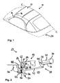
- Fig. 1 shows a top 10 of a convertible in its closed position in which a front hood portion 12 rests against a windshield frame 14 and is lockable with this.
- Fig. 1 only drawn to the left of a vehicle longitudinal centerline CC lying part of the top or the adjacent vehicle components.
- Components of a locking device are respectively arranged on both sides of the vehicle center, by means of which the top 10 with its front top section 12 can be locked on the windshield frame 14.
- the location of the left of the vehicle center locking components is in Fig. 1 dashed lines at 16 located.
- the (not shown) right locking components are arranged symmetrically to the vehicle longitudinal center line CC.
- the locking device comprises in the region 16 on the hood side a locking hook 18 which can be pivoted into a locking position (cf. Fig. 2 ), which engages under the locked top condition a corresponding locking hook engaging part on the windshield frame 14. After pivoting the locking hook 18 in an unlocked position, the top can be opened.
- the top opening is done by a hydraulically driven folding back the top 10 in a rear-side storage position in which the top 10 is folded in a top compartment 20 in the rear of the vehicle is housed and can be locked there by means of a locking device 22, the below with reference to the Fig. 2 to 6 is described.
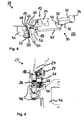
- Fig. 2 shows the arranged on a vehicle side part of the components of the locking device 22, which are particularly essential for understanding the present invention. These components are actually double, symmetrical to the center of the vehicle.
- Fig. 2 illustrates the locked in its rear-side storage position hood 10, of which in Fig. 2 a side hood frame front part 24 with the pivotally mounted thereto locking hook 18, a front part 24 fixedly arranged centering pin 26, a catch hook engaging part 28 and an actuating mechanism 30 for pivoting the locking hook 18 are visible.
- the top frame front part 24 forms together with the spanning this part, in Fig. 2
- the top hook engaging portion 28 is a projecting from the front part 24 sideways outwardly and mushroom-like at its free end pin section. In the region of this catch hook engaging part 28 is the transverse pivot axis of the locking hook 18, the in Fig. 2 is shown in its unlocked position.
- the front-side locking of the top 10 on the windshield frame 14 can take place by a pivoting of the closure hook 18 in the clockwise direction.
- the pivoting of the locking hook 18 is effected by an electric motor drive, of which in Fig. 2 only a cover-fixed linear guide 32 with a longitudinally movable tab 34 can be seen (eg., Spindle drive).
- the movement of the rider 34 along the linear guide 32 is converted into a corresponding pivotal movement of the closure hook 18 via a first link 36, a pivot plate 38, which is pivotable at 40 about a hood-fixed transverse axis, and a second link 42.
- the components 36, 38 and 42 together form the actuating mechanism 30 for pivoting the locking hook 18 between the illustrated unlocking position and a clockwise pivoted about 90 degrees locking position.
- centering pin 26 which serves to center the hood in the rear-side storage position, it may be a centering pin, which is also used for the front-side centering of the top 10. In the illustrated embodiment, however, the centering pin 26 is a part designed especially for centering in the rear-side storage position.
- Fig. 2 can be seen as a body-side component, a support member 46, on which pivotally projecting a funnel-like centering 48 to the rear, in which the centering pin 26 received in the rear side stored state of the top 10 and both in the vehicle longitudinal direction and in Vehicle transverse direction is centered.
- the pivoting mobility of the centering receptacle 28 is provided around a transverse axis, which is located in the region of the support member 46.
- the centering receptacle 48 is loaded in the illustrated state by the centering pin 26 downward or clockwise and pressed against the force of a compression spring 50 down or pivoted.
- the spring 50 is functionally parallel an elastic damper member 52 is arranged by means of which a kind of "resilient stop" for the pivoting of the centering 48 is formed, which counteracts a movement of the top 10 down.
- a movement of the locked top 10 is prevented by the engagement of a body side pivotally mounted about a transverse axis 54 fishing hook 56 with the hood-side fishing hook engaging part 28.
- a release of the locking of the top 10 can be initiated in a simple manner by driving the provided for pivoting the locking hook 18 locking drive.
- Fig. 3 shows the situation in which the locking hook 18 is pivoted a little way clockwise and with its free end a central portion of the fishing hook 56 against the force of a in the Fig. 2 to 5 not apparent spring 58 (see. Fig. 6 ) pushes forward or pivoted counterclockwise, so that the upper hook portion of the catch hook 56 comes out of engagement with the catch hook engaging portion 28.
- the locking hook 18 is pivoted back to its original position (unlocking position), so the fishing hook 56 pivots spring-driven again in the direction of its locking position (clockwise). Due to the slightly raised position of the top 10 and thus of the fishing hook engaging part 28 of the hook portion of the fishing hook 56 can not get into engagement with the engaging part 28 in this case.
- the top 10 is then moved by means of a hydraulic drive provided for this purpose in the closing direction, about to return to the in Fig. 1 To reach shown closed position.
- the embodiment described advantageously implements a passive locking of the top in the sense that this, apart from the motor or hydraulically driven top movement, no active drive any component of the locking device is required.
- the hood-side fishing hook engaging member 28 on the spring-loaded held in its locking position hook 56 strikes, the engagement member 28 acts on an overlying the hook area inclined surface or control surface 60 of the fishing hook 56 that thus the fishing hook 56 initially overcoming its spring preload is pivoted in the direction of its release position and then the engagement member 28 engages in the hook portion.
- Fig. 5 shown situation which in the further top movement in storage direction directly in the situation according to Fig. 2 opens, in which the top 10 is latched to the locking device 22 is held in its position.
- Fig. 6 shows in an oblique top view again some of the above-described components of the locking device 22nd
- the free end of the fishing hook 56 is formed by an easily accessible from above handle nose 62 on which the fishing hook 56 for the purpose of emergency release (in case of failure of the locking drive) can be attacked for pivoting.
- a locking device located in the area of the convertible top main bearing is used, which enters a locking engagement as soon as the top 10 reaches the storage position. Similar to a ski binding, the force of a spring preload is overcome immediately before reaching the storage position, for which a top hydraulic or an electric main drive supplies the necessary pressure.
- the to be overcome bias comes from an acted upon with spring pressure storage centering and is also for the locked stowed state of the hood of use, such as to secure the hood against dynamic loads while driving.
- the locking element of the locking device is a body-side hinged fishing hook, which engages a counterpart (fishing hook engaging part) on the front roof frame of the hood.
- the reverse arrangement of these two locking components is possible.
- the free end of the fishing hook for such a manual pivoting for a user is accessible from the outside.
- the free end from the top is easily accessible due to the body-side linkage of the fishing hook 56. Due to the total simple design, a special sensor for detecting the lock is unnecessary.
Landscapes
- Engineering & Computer Science (AREA)
- Mechanical Engineering (AREA)
- Lock And Its Accessories (AREA)
Claims (8)
- Capote d'un véhicule automobile, qui dans sa position de fermeture peut être verrouillée au moyen d'un crochet de fermeture (18) disposé sur une portion de capote avant (12), basculable dans une position de verrouillage sur une armature de vitre brise-vent (14) et peut être déplacée après le basculement du crochet de fermeture (18) dans une position de déverrouillage dans une position repliée vers l'arrière, dans laquelle la capote peut être bloquée au moyen d'un dispositif de blocage (22), moyennant quoi la capote présente un entraînement de verrouillage (32, 34) en liaison d'entraînement avec le crochet de fermeture (18) afin de basculer le crochet de fermeture (18) entre la position de verrouillage et la position de déverrouillage, moyennant quoi le dispositif de blocage (22) présente du côté de la carrosserie ou du côté de la capote un crochet d'arrêt (56), qui est basculable entre une position de blocage et une position de déblocage et dans la position de blocage en l'état bloqué de la capote vient en prise avec une pièce de mise en prise avec le crochet d'arrêt (28) du côté de la capote, resp. du côté de la carrosserie,
caractérisée en ce que le dispositif de blocage (22) présente un dispositif de ressort (50, 52, 48), contre la force de ressort duquel la capote se roule en position repliée, et en ce que le basculement du crochet d'arrêt (56) dans sa position de déblocage peut être provoqué afin de débloquer le blocage au moyen de l'entraînement de verrouillage (32, 34). - Capote selon la revendication 1, dans laquelle le dispositif de ressort (50, 52) est disposé du côté de la carrosserie.
- Capote selon la revendication 2, dans laquelle le dispositif de ressort (50, 52, 48) présente un réceptacle de centrage (48) précontraint par ressort dans la position repliée en sens contraire à la direction de déploiement de la capote afin de centrer une goupille de centrage (26) du côté de la capote.
- Capote selon une des revendications précédentes, dans laquelle le basculement du crochet d'arrêt (56) dans sa position de déblocage afin de débloquer le blocage est provoqué du fait qu'une portion du crochet de fermeture (18) vient buter contre une portion centrale du crochet d'arrêt (56).
- Capote selon un des revendications précédentes, dans laquelle le crochet d'arrêt (56) est basculable autour d'un axe transversal (54).
- Capote selon une des revendications précédentes, dans laquelle le crochet d'arrêt (56) est précontraint par ressort dans la direction de la position de blocage.
- Capote selon la revendication 6, dans laquelle le crochet d'arrêt (56) et la pièce de mise en prise avec le crochet d'arrêt (28) coopèrent lors du roulement de la capote en la position repliée de telle sorte que le crochet d'arrêt (56) soit d'abord basculé en surmontant sa précontrainte par ressort dans la direction de sa position de déblocage et est basculé en sens inverse par entraînement de ressort quand la position repliée est atteinte lors de la mise en prise avec la pièce de mise en prise avec le crochet d'arrêt (28).
- Capote selon la revendication 6, dans laquelle le crochet d'arrêt (56) est disposé du côté de la carrosserie et la pièce de mise en prise avec le crochet d'arrêt (28) est disposée du côté de la capote.
Applications Claiming Priority (2)
| Application Number | Priority Date | Filing Date | Title |
|---|---|---|---|
| DE102006020873A DE102006020873B4 (de) | 2006-05-04 | 2006-05-04 | Kraftfahrzeugverdeck |
| PCT/DE2007/000771 WO2007128269A1 (fr) | 2006-05-04 | 2007-04-30 | Capote pour véhicule automobile |
Publications (2)
| Publication Number | Publication Date |
|---|---|
| EP2013047A1 EP2013047A1 (fr) | 2009-01-14 |
| EP2013047B1 true EP2013047B1 (fr) | 2010-07-21 |
Family
ID=38441681
Family Applications (1)
| Application Number | Title | Priority Date | Filing Date |
|---|---|---|---|
| EP07722328A Not-in-force EP2013047B1 (fr) | 2006-05-04 | 2007-04-30 | Capote pour véhicule automobile |
Country Status (4)
| Country | Link |
|---|---|
| US (1) | US7802838B2 (fr) |
| EP (1) | EP2013047B1 (fr) |
| DE (2) | DE102006020873B4 (fr) |
| WO (1) | WO2007128269A1 (fr) |
Families Citing this family (6)
| Publication number | Priority date | Publication date | Assignee | Title |
|---|---|---|---|---|
| DE102007015705A1 (de) * | 2007-04-02 | 2008-10-09 | Wilhelm Karmann Gmbh | Verdeck für ein Kraftfahrzeug, insbesondere Cabriolet-Fahrzeug, mit einem faltbaren Dach |
| DE102008024725A1 (de) * | 2008-05-22 | 2009-12-03 | Webasto Ag | Faltverdeck mit einer Ablageverriegelung |
| DE102008033830A1 (de) * | 2008-07-19 | 2010-01-21 | Wilhelm Karmann Gmbh | Cabriolet-Fahrzeug mit einem in seiner Offenstellung lagesicherbaren Dach |
| DE102008060544B4 (de) * | 2008-11-24 | 2012-11-22 | Webasto Ag | Verdeck mit Arretierung in Ablageposition |
| DE102008061211A1 (de) * | 2008-12-09 | 2010-06-10 | Wilhelm Karmann Gmbh | Cabriolet-Fahrzeug mit einem in seiner Offenstellung lagesicherbaren Dach |
| DE102011051901A1 (de) | 2011-07-18 | 2013-01-24 | Dr. Ing. H.C. F. Porsche Aktiengesellschaft | Arretiereinrichtung für ein Verdeck |
Family Cites Families (7)
| Publication number | Priority date | Publication date | Assignee | Title |
|---|---|---|---|---|
| DE19507431C1 (de) | 1995-03-03 | 1996-08-01 | Daimler Benz Ag | Hardtop-Fahrzeug |
| DE19533802C1 (de) * | 1995-09-13 | 1997-03-06 | Porsche Ag | Verdeck für ein Fahrzeug, insbesondere Carbriolet |
| US6361086B1 (en) * | 1999-11-12 | 2002-03-26 | Daimlerchrysler Corporation | Mechanical latch |
| DE10147213B4 (de) | 2001-09-25 | 2004-07-29 | Dr.Ing.H.C. F. Porsche Ag | Verschluß zum lösbaren Verbinden eines Hardtops mit einer Karosserie eines Fahrzeugs |
| DE10241799B3 (de) | 2002-09-06 | 2004-03-11 | Cts Fahrzeug-Dachsysteme Gmbh | Verriegelungseinrichtung für ein verstellbares Fahrzeugdach |
| DE10313496B4 (de) * | 2003-03-25 | 2005-06-16 | Open Air Systems Gmbh | Verdeck eines Kraftfahrzeugs |
| DE102004052236A1 (de) | 2004-10-27 | 2006-05-04 | Wilhelm Karmann Gmbh | Verriegelungseinrichtung für ein Cabrioletverdeck |
-
2006
- 2006-05-04 DE DE102006020873A patent/DE102006020873B4/de not_active Expired - Fee Related
-
2007
- 2007-04-30 WO PCT/DE2007/000771 patent/WO2007128269A1/fr not_active Ceased
- 2007-04-30 US US12/299,243 patent/US7802838B2/en not_active Expired - Fee Related
- 2007-04-30 EP EP07722328A patent/EP2013047B1/fr not_active Not-in-force
- 2007-04-30 DE DE502007004491T patent/DE502007004491D1/de active Active
Also Published As
| Publication number | Publication date |
|---|---|
| EP2013047A1 (fr) | 2009-01-14 |
| DE102006020873A1 (de) | 2007-11-15 |
| WO2007128269A1 (fr) | 2007-11-15 |
| DE102006020873B4 (de) | 2008-08-21 |
| US7802838B2 (en) | 2010-09-28 |
| US20090072590A1 (en) | 2009-03-19 |
| DE502007004491D1 (de) | 2010-09-02 |
Similar Documents
| Publication | Publication Date | Title |
|---|---|---|
| EP1199202B1 (fr) | Véhicule convertible avec une capote escamotable sous un élément de couvercle dans la partie arrière du véhicule | |
| DE102004022426B4 (de) | Heckklappenanordnung | |
| EP1780354A2 (fr) | Agencement d'une porte coulissante de véhicule automobile | |
| EP2013047B1 (fr) | Capote pour véhicule automobile | |
| DE69613444T2 (de) | Sonnendach für Fahrzeug | |
| DE102004023614B4 (de) | Vorrichtung zur Abdeckung eines Stauraums eines Kraftfahrzeugs | |
| DE10051996B4 (de) | Cabriolet-Fahrzeug mit einem im rückwärtigen Fahrzeugbereich unterhalb eines Deckelteils ablegbaren Dach | |
| DE10138163C2 (de) | Verdeckkasten zur Aufnahme eines verstellbaren Fahrzeugverdecks | |
| DE102017121577B4 (de) | Verdeckkastendeckelanordnung mit Stelllenkern und Antriebslenkeranordnung | |
| DE60304475T2 (de) | Zur erleichterung des einführens von objekten unter einem faltdach im kofferraum eines kraftfahrzeugs verwendete vorrichtung | |
| DE69300834T2 (de) | Runge für eine Fahrzeug-Ladeplattform. | |
| EP2280840B1 (fr) | Capote pour un véhicule, notamment un véhicule décapotable, doté d'un toit pliant | |
| DE202008001247U1 (de) | Kraftfahrzeug | |
| DE102007006518B4 (de) | Anlenkung für einen Heckdeckel | |
| DE102007021490A1 (de) | Verdeck eines Cabriolet-Fahrzeugs | |
| DE10052001B4 (de) | Cabriolet-Fahrzeug mit einem im rückwärtigen Fahrzeugbereich unterhalb eines Deckelteils ablegbaren Dach | |
| EP1940640B1 (fr) | Dispositif de verrouillage d'un couvercle de logement de capote d'un cabriolet | |
| EP1656275A1 (fr) | Cabriolet | |
| DE102018132836B3 (de) | Verschlussvorrichtung mit Verriegelungshaken und Verdeck mit Verschlussvorrichtung | |
| DE102016124451A1 (de) | Verschlussvorrichtung mit Verschlusshaken und verfahrbarem Schlitten | |
| DE19501997A1 (de) | Verriegelungseinrichtung für das aufklappbare Verdeck eines offenen Automobils | |
| DE102016112966A1 (de) | Verschlussvorrichtung mit Verschlusshaken und verfahrbarem Schlitten | |
| EP1338453B1 (fr) | Dispositif de verrouillage et centrage pour un toit de véhicule ouvrant | |
| DE102006053048B4 (de) | Kraftfahrzeug mit einem unterhalb eines Deckelteils ablegbaren Dach oder Dachteil | |
| EP2383135B1 (fr) | Couvercle mobile |
Legal Events
| Date | Code | Title | Description |
|---|---|---|---|
| PUAI | Public reference made under article 153(3) epc to a published international application that has entered the european phase |
Free format text: ORIGINAL CODE: 0009012 |
|
| 17P | Request for examination filed |
Effective date: 20081014 |
|
| AK | Designated contracting states |
Kind code of ref document: A1 Designated state(s): AT BE BG CH CY CZ DE DK EE ES FI FR GB GR HU IE IS IT LI LT LU LV MC MT NL PL PT RO SE SI SK TR |
|
| AX | Request for extension of the european patent |
Extension state: AL BA HR MK RS |
|
| DAX | Request for extension of the european patent (deleted) | ||
| RBV | Designated contracting states (corrected) |
Designated state(s): DE FR GB IT |
|
| GRAP | Despatch of communication of intention to grant a patent |
Free format text: ORIGINAL CODE: EPIDOSNIGR1 |
|
| GRAS | Grant fee paid |
Free format text: ORIGINAL CODE: EPIDOSNIGR3 |
|
| GRAA | (expected) grant |
Free format text: ORIGINAL CODE: 0009210 |
|
| AK | Designated contracting states |
Kind code of ref document: B1 Designated state(s): DE FR GB IT |
|
| REG | Reference to a national code |
Ref country code: GB Ref legal event code: FG4D Free format text: NOT ENGLISH |
|
| REF | Corresponds to: |
Ref document number: 502007004491 Country of ref document: DE Date of ref document: 20100902 Kind code of ref document: P |
|
| PLBE | No opposition filed within time limit |
Free format text: ORIGINAL CODE: 0009261 |
|
| STAA | Information on the status of an ep patent application or granted ep patent |
Free format text: STATUS: NO OPPOSITION FILED WITHIN TIME LIMIT |
|
| 26N | No opposition filed |
Effective date: 20110426 |
|
| REG | Reference to a national code |
Ref country code: DE Ref legal event code: R097 Ref document number: 502007004491 Country of ref document: DE Effective date: 20110426 |
|
| REG | Reference to a national code |
Ref country code: DE Ref legal event code: R082 Ref document number: 502007004491 Country of ref document: DE Representative=s name: ROOS, PETER, DIPL.-PHYS.UNIV. DR.RER.NAT., DE Ref country code: DE Ref legal event code: R082 Ref document number: 502007004491 Country of ref document: DE Representative=s name: ROOS, PETER, DIPL.-PHYS. UNIV. DR.RER.NAT., DE |
|
| PGFP | Annual fee paid to national office [announced via postgrant information from national office to epo] |
Ref country code: GB Payment date: 20140423 Year of fee payment: 8 |
|
| PGFP | Annual fee paid to national office [announced via postgrant information from national office to epo] |
Ref country code: IT Payment date: 20140429 Year of fee payment: 8 Ref country code: FR Payment date: 20140416 Year of fee payment: 8 |
|
| GBPC | Gb: european patent ceased through non-payment of renewal fee |
Effective date: 20150430 |
|
| PG25 | Lapsed in a contracting state [announced via postgrant information from national office to epo] |
Ref country code: GB Free format text: LAPSE BECAUSE OF NON-PAYMENT OF DUE FEES Effective date: 20150430 Ref country code: IT Free format text: LAPSE BECAUSE OF NON-PAYMENT OF DUE FEES Effective date: 20150430 |
|
| REG | Reference to a national code |
Ref country code: FR Ref legal event code: ST Effective date: 20151231 |
|
| PG25 | Lapsed in a contracting state [announced via postgrant information from national office to epo] |
Ref country code: FR Free format text: LAPSE BECAUSE OF NON-PAYMENT OF DUE FEES Effective date: 20150430 |
|
| PGFP | Annual fee paid to national office [announced via postgrant information from national office to epo] |
Ref country code: DE Payment date: 20220419 Year of fee payment: 16 |
|
| REG | Reference to a national code |
Ref country code: DE Ref legal event code: R119 Ref document number: 502007004491 Country of ref document: DE |
|
| PG25 | Lapsed in a contracting state [announced via postgrant information from national office to epo] |
Ref country code: DE Free format text: LAPSE BECAUSE OF NON-PAYMENT OF DUE FEES Effective date: 20231103 |