EP2013057B1 - Siège de véhicule automobile - Google Patents
Siège de véhicule automobile Download PDFInfo
- Publication number
- EP2013057B1 EP2013057B1 EP07722318A EP07722318A EP2013057B1 EP 2013057 B1 EP2013057 B1 EP 2013057B1 EP 07722318 A EP07722318 A EP 07722318A EP 07722318 A EP07722318 A EP 07722318A EP 2013057 B1 EP2013057 B1 EP 2013057B1
- Authority
- EP
- European Patent Office
- Prior art keywords
- seat
- backrest
- motor vehicle
- seat part
- vehicle seat
- Prior art date
- Legal status (The legal status is an assumption and is not a legal conclusion. Google has not performed a legal analysis and makes no representation as to the accuracy of the status listed.)
- Not-in-force
Links
Images

Classifications
-
- B—PERFORMING OPERATIONS; TRANSPORTING
- B60—VEHICLES IN GENERAL
- B60N—SEATS SPECIALLY ADAPTED FOR VEHICLES; VEHICLE PASSENGER ACCOMMODATION NOT OTHERWISE PROVIDED FOR
- B60N2/00—Seats specially adapted for vehicles; Arrangement or mounting of seats in vehicles
- B60N2/24—Seats specially adapted for vehicles; Arrangement or mounting of seats in vehicles for particular purposes or particular vehicles
- B60N2/30—Non-dismountable or dismountable seats storable in a non-use position, e.g. foldable spare seats
- B60N2/3002—Non-dismountable or dismountable seats storable in a non-use position, e.g. foldable spare seats back-rest movements
- B60N2/3004—Non-dismountable or dismountable seats storable in a non-use position, e.g. foldable spare seats back-rest movements by rotation only
- B60N2/3009—Non-dismountable or dismountable seats storable in a non-use position, e.g. foldable spare seats back-rest movements by rotation only about transversal axis
- B60N2/3013—Non-dismountable or dismountable seats storable in a non-use position, e.g. foldable spare seats back-rest movements by rotation only about transversal axis the back-rest being hinged on the vehicle frame
-
- B—PERFORMING OPERATIONS; TRANSPORTING
- B60—VEHICLES IN GENERAL
- B60N—SEATS SPECIALLY ADAPTED FOR VEHICLES; VEHICLE PASSENGER ACCOMMODATION NOT OTHERWISE PROVIDED FOR
- B60N2/00—Seats specially adapted for vehicles; Arrangement or mounting of seats in vehicles
- B60N2/24—Seats specially adapted for vehicles; Arrangement or mounting of seats in vehicles for particular purposes or particular vehicles
- B60N2/30—Non-dismountable or dismountable seats storable in a non-use position, e.g. foldable spare seats
- B60N2/3038—Cushion movements
- B60N2/3063—Cushion movements by composed movement
- B60N2/3065—Cushion movements by composed movement in a longitudinal-vertical plane
-
- B—PERFORMING OPERATIONS; TRANSPORTING
- B60—VEHICLES IN GENERAL
- B60N—SEATS SPECIALLY ADAPTED FOR VEHICLES; VEHICLE PASSENGER ACCOMMODATION NOT OTHERWISE PROVIDED FOR
- B60N2/00—Seats specially adapted for vehicles; Arrangement or mounting of seats in vehicles
- B60N2/24—Seats specially adapted for vehicles; Arrangement or mounting of seats in vehicles for particular purposes or particular vehicles
- B60N2/30—Non-dismountable or dismountable seats storable in a non-use position, e.g. foldable spare seats
- B60N2/3088—Non-dismountable or dismountable seats storable in a non-use position, e.g. foldable spare seats characterised by the mechanical link
- B60N2/309—Non-dismountable or dismountable seats storable in a non-use position, e.g. foldable spare seats characterised by the mechanical link rods
Definitions
- the present invention relates to a motor vehicle seat, in which the movement of the backrest is coupled with the movement of the seat part, and a motor vehicle with such a motor vehicle seat.
- Motor vehicle seats are known from the prior art, comprising a backrest and a seat part.
- the backrests of the known seats can be folded or pivoted in the direction of the seat part.
- a simple motor vehicle seat with a foldablematiiehne and a forward lowered seat, the movements of which are coupled in a certain range shows the document US 7,014,263 B2 .
- the seat In the area of a front pivoting angle of the backrest, the seat is taken in its lowering movement.
- the coupling is canceled, the seat performs correspondingly no movement.
- the document describes DE 103 55 765 A1 a motor vehicle seat with a folding backrest and a lowerable seat part, wherein the backrest can be folded in the direction of the seat part.
- a mechanism is further provided, so that the seat part can be lowered from a raised position of use into a lowered position displaced to the front.
- a coupling member is provided in order to couple the movement of the backrest with the movement of the seat part.
- a locking mechanism is used to lock the seat part in the position of use. This serves the purpose of preventing unintentional forward displacement of the seat in a collision accident safely.
- the coupling member is designed such that the locking mechanism is only unlocked when folding the backrest to the seat part when the backrest occupies a predetermined angle of inclination.
- the coupling member is in this case designed as push or push rod, which presses on one or more adjustment lever of the mechanism of the seat part
- the known motor vehicle seat has been proven, but has the disadvantage that the proposed mechanism comprises many items and thus requires a comparatively complex assembly.
- a vehicle seat with a seat back pivoting backrest is known.
- the seat assembly is displaceable after a release of the seat around a main pivot pin from a sitting position to a stowed position.
- the US 5,570,931 A discloses a stowable seat of the rear row of seats, which can be pivoted after a release of the seat in the rear area via a parallelogram forward and downward.
- a vehicle seat known, which is held displaceable via a parallelogram.
- two wings are arranged at the front and rear seating area.
- the vehicle seat has an adjustment device that includes a bow hole disposed in the rear swing. In the bow hole a circular disc is guided, which is connected to a pinion. Turning the pinion adjusts the four-bar linkage and at the same time the backrest.
- the invention is further based on the object to provide a motor vehicle with such an advantageous motor vehicle seat.
- a motor vehicle seat with the features of claim 1.
- locking elements By preferably arranged on the structure of the backrest in the region of the pivot axis locking elements is a very inexpensive manufacturable locking the seat against unintentional lowering in the event of a collision accident possible.
- the locking elements can be formed particularly advantageous as a bayonet-like hooks on the hinge fittings of the backrest.
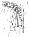
- a motor vehicle seat 1 comprises a seat base 11 for attachment to a vehicle body.
- a seat base 11 for attachment to a vehicle body.
- means for longitudinal adjustment of the seat 1 in the vehicle can be provided on the seat base 11. This will not be discussed in further detail here.
- the structure of a backrest 2 is also hinged in a fitting 6 in a known manner about the axis A pivotable.
- a padding 22 On the structure 21 of the backrest 2 is in a conventional manner, a padding 22.
- a manual adjustment of the backrest 2 is to take place, additional locking devices are provided, preferably in the region of the hinge fittings 6, in order to be able to stagger the backrest 2 in different positions or to adjust it continuously relative to the seat base 11. These locking devices are well known, which is why further details are not discussed here. Otherwise, a motor adjustment of the backrest 2 is desired, preferably electrical drive means are again preferably arranged in the area next to or between the hinge fittings 6. This is also known from the prior art.
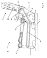
- the seat part 3 forming the seat comprises a supporting structure 31 and a padding 32 lying thereon. At its front end, the structure 31 is hinged to the seat base 11 by a support arm 8. In the illustrated raised Use position of the seat part 3, the support arm 8 is erected approximately vertically above the seat base 11. As a result, the front edge of the seat part 3 assumes a high position as shown. When lowering the seat part 3 moves forward, whereby the support arm 8 is stored to the front end of the seat base 11 out. The front edge of the seat 3 is thereby lowered, thereby freeing the space for complete removal of the backrest 2.
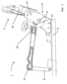
- a push rod 9 For coupling the movements of the seat part 3 to the thrust movement of the backrest 2 is a push rod 9, which is hinged at its front end to the support arm 8 articulated. In known manner, it is provided that this coupling is made only at a pivoting of the backrest 2 outside the range of use positions, ie outside the comfort setting range. This is configured at the connection point to the backrest 2.
- the for driving a arranged on the backrest 2 driving pin 12 provided arcuate slot 92 in the push rod 9 accordingly provides an idle travel. With a slight movement of the backrest 2 in the region of the use positions, the driving pin 12 moves only within the recess of the arcuate slot 92. The push rod 9 is not actuated by such a movement.
- the seat part 3 In the raised use positions of the seat part 3, its structure 31 is preferably fixed for safety reasons at its rear end by a liftable lock against the seat base 11. This is intended to avoid inadvertent lowering of the seat part 3 in the event of a collision accident, if in this case the mechanical coupling of the structure 31 of the seat surface 3 to the backrest 2 is destroyed by an occurring overload.
- the intended locking is carried out by preferably on both sides on the rigidly connected to the backrest 2 parts of the hinge fittings 6 arranged hooks 61 or similar locking elements which engage around a locking element, such as the pin 13 shown when the backrest 2 is in the range of use positions. In a pivoting movement of the backrest 2 out of the range of use positions, the hooks 61 move on a circular path and thereby leave the illustrated engagement position. Then the pins 13 are released for movement in the backdrop 91.
- rearwardly projecting arms or projections are provided, which rest on corresponding abutment points on the seat base 11 in the position of use.
- the slide guide 91, 13 relieved of the forces due to the seat occupancy.
- this is not apparent in the drawings because of the chosen perspective.
Landscapes
- Engineering & Computer Science (AREA)
- Aviation & Aerospace Engineering (AREA)
- Transportation (AREA)
- Mechanical Engineering (AREA)
- Seats For Vehicles (AREA)
- Chairs For Special Purposes, Such As Reclining Chairs (AREA)
Claims (6)
- Siège de véhicule automobile (1), comportant un dossier (2) pivotable et une partie d'assise (3) abaissable couplés entre eux par le biais d'une jonction mécanique (9, 13), pour rabaisser la partie d'assise (3) lors d'un pivotement du dossier (2) hors de la zone des positions d'utilisation et un verrouillage (13, 61) relevable qui est conçu pour fixer la partie d'assise (3) comprenant une structure (31) portante par rapport à une base de siège (11) à fixer par rapport au véhicule, lorsque le dossier (2) se trouve dans la zone de ses positions d'utilisation, et pour le relever lorsqu'il en sort et le verrouillage comprenant un élément de blocage (61) disposé à proximité de l'articulation pivotante (A) au niveau du dossier (2) et pouvant être amené par son pivotement en mise en prise avec un élément d'encliquetage (13) au niveau de la partie d'assise (3) et l'extrémité arrière de la structure (31) de la partie d'assise (3) étant guidée dans un coulisseau (91), caractérisé en ce que le mouvement d'abaissement de la partie d'assise (3) est couplé au mouvement de pivotement du dossier (2), par une barre de poussée (9) et le coulisseau (91) étant réalisé dans la barre de poussée (9).
- Siège de véhicule automobile (1) selon la revendication 1, l'élément de blocage (7) étant un crochet (61) de préférence en forme de baïonnette qui peut être déplacé dans une position engrenant un tenon (13) au niveau de l'extrémité de la structure (31) de la partie d'assise (3).
- Siège de véhicule automobile (1) selon la revendication 2, le crochet (61) étant réalisé au niveau de la partie de la ferrure d'articulation (6) reliée à la structure (21) du dossier (2).
- Siège de véhicule automobile (1) selon la revendication 1, la jonction de la barre de poussée (9) au dossier (2) comportant une course libre.
- Siège de véhicule automobile (1) selon la revendication 4, la jonction de la barre de poussée (9) au dossier (2) étant actionnée par le biais d'un boulon engrenant (12) disposé au niveau de la structure (21) du dossier, ledit boulon étant logé dans un trou oblong (92) de la barre de poussée (9).
- Siège de véhicule automobile (1) selon l'une quelconque des revendications précédentes, la structure (31) de la partie d'assise (3) étant soutenue, dans sa position d'utilisation, dans un support, au niveau de son extrémité arrière, par rapport à la base de siège (11).
Applications Claiming Priority (2)
| Application Number | Priority Date | Filing Date | Title |
|---|---|---|---|
| DE102006022800A DE102006022800A1 (de) | 2006-04-27 | 2006-04-27 | Kraftfahrzeugsitz |
| PCT/DE2007/000761 WO2007124729A1 (fr) | 2006-04-27 | 2007-04-27 | Siège de véhicule automobile |
Publications (2)
| Publication Number | Publication Date |
|---|---|
| EP2013057A1 EP2013057A1 (fr) | 2009-01-14 |
| EP2013057B1 true EP2013057B1 (fr) | 2011-07-20 |
Family
ID=38512237
Family Applications (1)
| Application Number | Title | Priority Date | Filing Date |
|---|---|---|---|
| EP07722318A Not-in-force EP2013057B1 (fr) | 2006-04-27 | 2007-04-27 | Siège de véhicule automobile |
Country Status (4)
| Country | Link |
|---|---|
| EP (1) | EP2013057B1 (fr) |
| AT (1) | ATE516991T1 (fr) |
| DE (1) | DE102006022800A1 (fr) |
| WO (1) | WO2007124729A1 (fr) |
Cited By (1)
| Publication number | Priority date | Publication date | Assignee | Title |
|---|---|---|---|---|
| DE102013225123A1 (de) * | 2013-12-06 | 2015-06-11 | Johnson Controls Gmbh | Höhenverstell- und Schwenkvorrichtung für einen Sitz |
Families Citing this family (5)
| Publication number | Priority date | Publication date | Assignee | Title |
|---|---|---|---|---|
| JP5119910B2 (ja) * | 2007-12-26 | 2013-01-16 | トヨタ紡織株式会社 | 車両用シート |
| JP5119911B2 (ja) * | 2007-12-26 | 2013-01-16 | トヨタ紡織株式会社 | 車両用シート |
| JP6237465B2 (ja) | 2014-05-23 | 2017-11-29 | トヨタ紡織株式会社 | 乗物用シート |
| DE102014225692B4 (de) * | 2014-08-27 | 2017-06-08 | Adient Luxembourg Holding S.à.r.l. | Fahrzeugsitz, insbesondere Kraftfahrzeugsitz |
| DE102016224625A1 (de) * | 2016-12-09 | 2018-06-14 | Brose Fahrzeugteile Gmbh & Co. Kg, Coburg | Fahrzeugsitz mit Sperrmechanimus zur Sperrung eines zumindest abschnittsweise absenkbaren Polsterträgers bei einer Verstellung einer Rückenlehne |
Family Cites Families (4)
| Publication number | Priority date | Publication date | Assignee | Title |
|---|---|---|---|---|
| US5570931A (en) * | 1995-09-29 | 1996-11-05 | Chrysler Corporation | Vehicle adjustable and stowable rear seat |
| EP1341683B1 (fr) * | 2000-12-11 | 2005-11-16 | Intier Automotive Inc. | Ensemble siege escamotable avec coussin de siege en porte-a-faux |
| DE10244293B4 (de) * | 2002-09-23 | 2007-10-31 | C. Rob. Hammerstein Gmbh & Co. Kg | Kraftfahrzeugsitz, insbesondere Fondsitz |
| US7887134B2 (en) * | 2005-04-20 | 2011-02-15 | Johnson Controls Technology Company | Interlock for a seat recliner mechanism |
-
2006
- 2006-04-27 DE DE102006022800A patent/DE102006022800A1/de not_active Ceased
-
2007
- 2007-04-27 AT AT07722318T patent/ATE516991T1/de active
- 2007-04-27 EP EP07722318A patent/EP2013057B1/fr not_active Not-in-force
- 2007-04-27 WO PCT/DE2007/000761 patent/WO2007124729A1/fr not_active Ceased
Cited By (2)
| Publication number | Priority date | Publication date | Assignee | Title |
|---|---|---|---|---|
| DE102013225123A1 (de) * | 2013-12-06 | 2015-06-11 | Johnson Controls Gmbh | Höhenverstell- und Schwenkvorrichtung für einen Sitz |
| DE102013225123B4 (de) * | 2013-12-06 | 2020-12-17 | Adient Luxembourg Holding S.À R.L. | Fahrzeugsitz mit einer Höhenverstell- und Schwenkvorrichtung |
Also Published As
| Publication number | Publication date |
|---|---|
| ATE516991T1 (de) | 2011-08-15 |
| EP2013057A1 (fr) | 2009-01-14 |
| DE102006022800A1 (de) | 2007-11-08 |
| WO2007124729A1 (fr) | 2007-11-08 |
Similar Documents
| Publication | Publication Date | Title |
|---|---|---|
| WO2019096774A2 (fr) | Siège de véhicule à entrée facile | |
| EP1615796B1 (fr) | Siege de vehicule | |
| EP0985575A2 (fr) | Siège arrière de véhicule automobile à dossier rabattable et assise abaissable | |
| EP2183127B1 (fr) | Siège de véhicule pour véhicule automobile | |
| DE102005060444B4 (de) | Fahrzeugsitz mit Bodenstellung | |
| DE102008004230A1 (de) | Kraftfahrzeugsitz mit einem Viergelenk-Lehnenschwenkmechanismus und einem Zweigelenk-Sitzteilschwenkmechanismus | |
| EP4139163B1 (fr) | Siège de véhicule doté d'un levier cinématique | |
| DE10257601A1 (de) | Sitzvorrichtung mit einem Befestigungssystem | |
| DE60113861T2 (de) | Fahrzeugsitzbereich zum Bewegen aus einer Benutzungspostion in eine Verstaupos ition | |
| EP1718494A1 (fr) | Siege de vehicule, notamment pour une automobile, comprenant un dossier rabattable et une base d'assise rabattable et procede correspondant | |
| EP2013057A1 (fr) | Siège de véhicule automobile | |
| DE102013225123A1 (de) | Höhenverstell- und Schwenkvorrichtung für einen Sitz | |
| DE102006015180A1 (de) | Auslösevorrichtung für ein Tischteil eines Sitzsystemes für Fahrzeuge zur Personenbeförderung | |
| DE102010046562B4 (de) | Sitz oder Sitzanlage für ein Kraftfahrzeug und insbesondere einen Lieferwagen | |
| EP1193112B1 (fr) | Véhicule automobile à siège rabattable | |
| EP1375244B1 (fr) | Appui-tête pour véhicules automobiles | |
| DE10238487A1 (de) | Fahrzeugsitz | |
| DE102014214564B4 (de) | Fahrzeugsitz, insbesondere Kraftfahrzeugsitz | |
| DE10318718A1 (de) | Verstellbarer Kraftfahrzeugsitz, insbesondere für die zweite und dritte Sitzreihe | |
| DE102006056715B4 (de) | Fahrzeugsitz, insbesondere Kraftfahrzeugsitz | |
| DE102019217911B3 (de) | Sitzanordnung | |
| DE102020205107B4 (de) | Fahrzeugsitz mit einem Kinematikhebel mit integriertem Betätigungsabschnitt | |
| EP1968815B1 (fr) | Siege de vehicule a moteur dont le deplacement du dossier est couple au deplacement de la partie assise et vehicule a moteur equipe d'un tel siege | |
| EP2048023B1 (fr) | Siège de véhicule doté d'un mécanisme de pivotement du dossier | |
| DE112006001386B4 (de) | Kopfstütze für ein Cabrio-Kraftfahrzeug |
Legal Events
| Date | Code | Title | Description |
|---|---|---|---|
| PUAI | Public reference made under article 153(3) epc to a published international application that has entered the european phase |
Free format text: ORIGINAL CODE: 0009012 |
|
| 17P | Request for examination filed |
Effective date: 20081124 |
|
| AK | Designated contracting states |
Kind code of ref document: A1 Designated state(s): AT BE BG CH CY CZ DE DK EE ES FI FR GB GR HU IE IS IT LI LT LU LV MC MT NL PL PT RO SE SI SK TR |
|
| AX | Request for extension of the european patent |
Extension state: AL BA HR MK RS |
|
| RIN1 | Information on inventor provided before grant (corrected) |
Inventor name: MCLAUGHLIN, MATTHEW, J. Inventor name: KULIHA, NORBERT Inventor name: VENTURA, KEVIN Inventor name: TAME, OMAR, D. Inventor name: ZEIMIS, PETER, PAUL, III |
|
| 17Q | First examination report despatched |
Effective date: 20100309 |
|
| GRAP | Despatch of communication of intention to grant a patent |
Free format text: ORIGINAL CODE: EPIDOSNIGR1 |
|
| DAX | Request for extension of the european patent (deleted) | ||
| GRAS | Grant fee paid |
Free format text: ORIGINAL CODE: EPIDOSNIGR3 |
|
| GRAA | (expected) grant |
Free format text: ORIGINAL CODE: 0009210 |
|
| AK | Designated contracting states |
Kind code of ref document: B1 Designated state(s): AT BE BG CH CY CZ DE DK EE ES FI FR GB GR HU IE IS IT LI LT LU LV MC MT NL PL PT RO SE SI SK TR |
|
| REG | Reference to a national code |
Ref country code: GB Ref legal event code: FG4D Free format text: NOT ENGLISH |
|
| REG | Reference to a national code |
Ref country code: CH Ref legal event code: EP |
|
| REG | Reference to a national code |
Ref country code: DE Ref legal event code: R096 Ref document number: 502007007721 Country of ref document: DE Effective date: 20110915 |
|
| REG | Reference to a national code |
Ref country code: NL Ref legal event code: VDEP Effective date: 20110720 |
|
| PG25 | Lapsed in a contracting state [announced via postgrant information from national office to epo] |
Ref country code: SE Free format text: LAPSE BECAUSE OF FAILURE TO SUBMIT A TRANSLATION OF THE DESCRIPTION OR TO PAY THE FEE WITHIN THE PRESCRIBED TIME-LIMIT Effective date: 20110720 Ref country code: FI Free format text: LAPSE BECAUSE OF FAILURE TO SUBMIT A TRANSLATION OF THE DESCRIPTION OR TO PAY THE FEE WITHIN THE PRESCRIBED TIME-LIMIT Effective date: 20110720 Ref country code: LT Free format text: LAPSE BECAUSE OF FAILURE TO SUBMIT A TRANSLATION OF THE DESCRIPTION OR TO PAY THE FEE WITHIN THE PRESCRIBED TIME-LIMIT Effective date: 20110720 Ref country code: IS Free format text: LAPSE BECAUSE OF FAILURE TO SUBMIT A TRANSLATION OF THE DESCRIPTION OR TO PAY THE FEE WITHIN THE PRESCRIBED TIME-LIMIT Effective date: 20111120 Ref country code: NL Free format text: LAPSE BECAUSE OF FAILURE TO SUBMIT A TRANSLATION OF THE DESCRIPTION OR TO PAY THE FEE WITHIN THE PRESCRIBED TIME-LIMIT Effective date: 20110720 Ref country code: PT Free format text: LAPSE BECAUSE OF FAILURE TO SUBMIT A TRANSLATION OF THE DESCRIPTION OR TO PAY THE FEE WITHIN THE PRESCRIBED TIME-LIMIT Effective date: 20111121 |
|
| REG | Reference to a national code |
Ref country code: IE Ref legal event code: FD4D |
|
| PG25 | Lapsed in a contracting state [announced via postgrant information from national office to epo] |
Ref country code: PL Free format text: LAPSE BECAUSE OF FAILURE TO SUBMIT A TRANSLATION OF THE DESCRIPTION OR TO PAY THE FEE WITHIN THE PRESCRIBED TIME-LIMIT Effective date: 20110720 Ref country code: CY Free format text: LAPSE BECAUSE OF FAILURE TO SUBMIT A TRANSLATION OF THE DESCRIPTION OR TO PAY THE FEE WITHIN THE PRESCRIBED TIME-LIMIT Effective date: 20110720 Ref country code: SI Free format text: LAPSE BECAUSE OF FAILURE TO SUBMIT A TRANSLATION OF THE DESCRIPTION OR TO PAY THE FEE WITHIN THE PRESCRIBED TIME-LIMIT Effective date: 20110720 Ref country code: GR Free format text: LAPSE BECAUSE OF FAILURE TO SUBMIT A TRANSLATION OF THE DESCRIPTION OR TO PAY THE FEE WITHIN THE PRESCRIBED TIME-LIMIT Effective date: 20111021 Ref country code: LV Free format text: LAPSE BECAUSE OF FAILURE TO SUBMIT A TRANSLATION OF THE DESCRIPTION OR TO PAY THE FEE WITHIN THE PRESCRIBED TIME-LIMIT Effective date: 20110720 |
|
| PG25 | Lapsed in a contracting state [announced via postgrant information from national office to epo] |
Ref country code: CZ Free format text: LAPSE BECAUSE OF FAILURE TO SUBMIT A TRANSLATION OF THE DESCRIPTION OR TO PAY THE FEE WITHIN THE PRESCRIBED TIME-LIMIT Effective date: 20110720 Ref country code: IE Free format text: LAPSE BECAUSE OF FAILURE TO SUBMIT A TRANSLATION OF THE DESCRIPTION OR TO PAY THE FEE WITHIN THE PRESCRIBED TIME-LIMIT Effective date: 20110720 Ref country code: SK Free format text: LAPSE BECAUSE OF FAILURE TO SUBMIT A TRANSLATION OF THE DESCRIPTION OR TO PAY THE FEE WITHIN THE PRESCRIBED TIME-LIMIT Effective date: 20110720 |
|
| PLBE | No opposition filed within time limit |
Free format text: ORIGINAL CODE: 0009261 |
|
| STAA | Information on the status of an ep patent application or granted ep patent |
Free format text: STATUS: NO OPPOSITION FILED WITHIN TIME LIMIT |
|
| PG25 | Lapsed in a contracting state [announced via postgrant information from national office to epo] |
Ref country code: RO Free format text: LAPSE BECAUSE OF FAILURE TO SUBMIT A TRANSLATION OF THE DESCRIPTION OR TO PAY THE FEE WITHIN THE PRESCRIBED TIME-LIMIT Effective date: 20110720 Ref country code: IT Free format text: LAPSE BECAUSE OF FAILURE TO SUBMIT A TRANSLATION OF THE DESCRIPTION OR TO PAY THE FEE WITHIN THE PRESCRIBED TIME-LIMIT Effective date: 20110720 Ref country code: EE Free format text: LAPSE BECAUSE OF FAILURE TO SUBMIT A TRANSLATION OF THE DESCRIPTION OR TO PAY THE FEE WITHIN THE PRESCRIBED TIME-LIMIT Effective date: 20110720 |
|
| 26N | No opposition filed |
Effective date: 20120423 |
|
| PG25 | Lapsed in a contracting state [announced via postgrant information from national office to epo] |
Ref country code: DK Free format text: LAPSE BECAUSE OF FAILURE TO SUBMIT A TRANSLATION OF THE DESCRIPTION OR TO PAY THE FEE WITHIN THE PRESCRIBED TIME-LIMIT Effective date: 20110720 |
|
| REG | Reference to a national code |
Ref country code: DE Ref legal event code: R097 Ref document number: 502007007721 Country of ref document: DE Effective date: 20120423 |
|
| PGFP | Annual fee paid to national office [announced via postgrant information from national office to epo] |
Ref country code: GB Payment date: 20120419 Year of fee payment: 6 |
|
| BERE | Be: lapsed |
Owner name: MAGNA SEATING (GEMANY) G.M.B.H. Effective date: 20120430 |
|
| PG25 | Lapsed in a contracting state [announced via postgrant information from national office to epo] |
Ref country code: MC Free format text: LAPSE BECAUSE OF NON-PAYMENT OF DUE FEES Effective date: 20120430 |
|
| REG | Reference to a national code |
Ref country code: CH Ref legal event code: PL |
|
| PG25 | Lapsed in a contracting state [announced via postgrant information from national office to epo] |
Ref country code: CH Free format text: LAPSE BECAUSE OF NON-PAYMENT OF DUE FEES Effective date: 20120430 Ref country code: LI Free format text: LAPSE BECAUSE OF NON-PAYMENT OF DUE FEES Effective date: 20120430 Ref country code: BE Free format text: LAPSE BECAUSE OF NON-PAYMENT OF DUE FEES Effective date: 20120430 |
|
| PG25 | Lapsed in a contracting state [announced via postgrant information from national office to epo] |
Ref country code: ES Free format text: LAPSE BECAUSE OF FAILURE TO SUBMIT A TRANSLATION OF THE DESCRIPTION OR TO PAY THE FEE WITHIN THE PRESCRIBED TIME-LIMIT Effective date: 20111031 |
|
| REG | Reference to a national code |
Ref country code: AT Ref legal event code: MM01 Ref document number: 516991 Country of ref document: AT Kind code of ref document: T Effective date: 20120427 |
|
| PG25 | Lapsed in a contracting state [announced via postgrant information from national office to epo] |
Ref country code: BG Free format text: LAPSE BECAUSE OF FAILURE TO SUBMIT A TRANSLATION OF THE DESCRIPTION OR TO PAY THE FEE WITHIN THE PRESCRIBED TIME-LIMIT Effective date: 20111020 |
|
| PG25 | Lapsed in a contracting state [announced via postgrant information from national office to epo] |
Ref country code: AT Free format text: LAPSE BECAUSE OF NON-PAYMENT OF DUE FEES Effective date: 20120427 Ref country code: MT Free format text: LAPSE BECAUSE OF FAILURE TO SUBMIT A TRANSLATION OF THE DESCRIPTION OR TO PAY THE FEE WITHIN THE PRESCRIBED TIME-LIMIT Effective date: 20110720 |
|
| PGFP | Annual fee paid to national office [announced via postgrant information from national office to epo] |
Ref country code: FR Payment date: 20130515 Year of fee payment: 7 |
|
| GBPC | Gb: european patent ceased through non-payment of renewal fee |
Effective date: 20130427 |
|
| PG25 | Lapsed in a contracting state [announced via postgrant information from national office to epo] |
Ref country code: GB Free format text: LAPSE BECAUSE OF NON-PAYMENT OF DUE FEES Effective date: 20130427 |
|
| PG25 | Lapsed in a contracting state [announced via postgrant information from national office to epo] |
Ref country code: TR Free format text: LAPSE BECAUSE OF FAILURE TO SUBMIT A TRANSLATION OF THE DESCRIPTION OR TO PAY THE FEE WITHIN THE PRESCRIBED TIME-LIMIT Effective date: 20110720 |
|
| PG25 | Lapsed in a contracting state [announced via postgrant information from national office to epo] |
Ref country code: LU Free format text: LAPSE BECAUSE OF NON-PAYMENT OF DUE FEES Effective date: 20120427 |
|
| PG25 | Lapsed in a contracting state [announced via postgrant information from national office to epo] |
Ref country code: HU Free format text: LAPSE BECAUSE OF FAILURE TO SUBMIT A TRANSLATION OF THE DESCRIPTION OR TO PAY THE FEE WITHIN THE PRESCRIBED TIME-LIMIT Effective date: 20070427 |
|
| REG | Reference to a national code |
Ref country code: FR Ref legal event code: ST Effective date: 20141231 |
|
| PG25 | Lapsed in a contracting state [announced via postgrant information from national office to epo] |
Ref country code: FR Free format text: LAPSE BECAUSE OF NON-PAYMENT OF DUE FEES Effective date: 20140430 |
|
| PGFP | Annual fee paid to national office [announced via postgrant information from national office to epo] |
Ref country code: DE Payment date: 20240418 Year of fee payment: 18 |
|
| REG | Reference to a national code |
Ref country code: DE Ref legal event code: R119 Ref document number: 502007007721 Country of ref document: DE |
|
| PG25 | Lapsed in a contracting state [announced via postgrant information from national office to epo] |
Ref country code: DE Free format text: LAPSE BECAUSE OF NON-PAYMENT OF DUE FEES Effective date: 20251104 |