EP2013454B1 - Abgasreinigungsvorrichtung für einen verbrennungsmotor - Google Patents
Abgasreinigungsvorrichtung für einen verbrennungsmotor Download PDFInfo
- Publication number
- EP2013454B1 EP2013454B1 EP07742856A EP07742856A EP2013454B1 EP 2013454 B1 EP2013454 B1 EP 2013454B1 EP 07742856 A EP07742856 A EP 07742856A EP 07742856 A EP07742856 A EP 07742856A EP 2013454 B1 EP2013454 B1 EP 2013454B1
- Authority
- EP
- European Patent Office
- Prior art keywords
- exhaust gas
- addition
- reducing agent
- fuel
- temperature
- Prior art date
- Legal status (The legal status is an assumption and is not a legal conclusion. Google has not performed a legal analysis and makes no representation as to the accuracy of the status listed.)
- Not-in-force
Links
Images


Classifications
-
- F—MECHANICAL ENGINEERING; LIGHTING; HEATING; WEAPONS; BLASTING
- F01—MACHINES OR ENGINES IN GENERAL; ENGINE PLANTS IN GENERAL; STEAM ENGINES
- F01N—GAS-FLOW SILENCERS OR EXHAUST APPARATUS FOR MACHINES OR ENGINES IN GENERAL; GAS-FLOW SILENCERS OR EXHAUST APPARATUS FOR INTERNAL-COMBUSTION ENGINES
- F01N3/00—Exhaust or silencing apparatus having means for purifying, rendering innocuous, or otherwise treating exhaust
- F01N3/08—Exhaust or silencing apparatus having means for purifying, rendering innocuous, or otherwise treating exhaust for rendering innocuous
- F01N3/0807—Exhaust or silencing apparatus having means for purifying, rendering innocuous, or otherwise treating exhaust for rendering innocuous by using absorbents or adsorbents
- F01N3/0821—Exhaust or silencing apparatus having means for purifying, rendering innocuous, or otherwise treating exhaust for rendering innocuous by using absorbents or adsorbents combined with particulate filter
-
- F—MECHANICAL ENGINEERING; LIGHTING; HEATING; WEAPONS; BLASTING
- F01—MACHINES OR ENGINES IN GENERAL; ENGINE PLANTS IN GENERAL; STEAM ENGINES
- F01N—GAS-FLOW SILENCERS OR EXHAUST APPARATUS FOR MACHINES OR ENGINES IN GENERAL; GAS-FLOW SILENCERS OR EXHAUST APPARATUS FOR INTERNAL-COMBUSTION ENGINES
- F01N3/00—Exhaust or silencing apparatus having means for purifying, rendering innocuous, or otherwise treating exhaust
- F01N3/02—Exhaust or silencing apparatus having means for purifying, rendering innocuous, or otherwise treating exhaust for cooling, or for removing solid constituents of, exhaust
- F01N3/021—Exhaust or silencing apparatus having means for purifying, rendering innocuous, or otherwise treating exhaust for cooling, or for removing solid constituents of, exhaust by means of filters
- F01N3/023—Exhaust or silencing apparatus having means for purifying, rendering innocuous, or otherwise treating exhaust for cooling, or for removing solid constituents of, exhaust by means of filters using means for regenerating the filters, e.g. by burning trapped particles
- F01N3/025—Exhaust or silencing apparatus having means for purifying, rendering innocuous, or otherwise treating exhaust for cooling, or for removing solid constituents of, exhaust by means of filters using means for regenerating the filters, e.g. by burning trapped particles using fuel burner or by adding fuel to exhaust
- F01N3/0253—Exhaust or silencing apparatus having means for purifying, rendering innocuous, or otherwise treating exhaust for cooling, or for removing solid constituents of, exhaust by means of filters using means for regenerating the filters, e.g. by burning trapped particles using fuel burner or by adding fuel to exhaust adding fuel to exhaust gases
-
- F—MECHANICAL ENGINEERING; LIGHTING; HEATING; WEAPONS; BLASTING
- F01—MACHINES OR ENGINES IN GENERAL; ENGINE PLANTS IN GENERAL; STEAM ENGINES
- F01N—GAS-FLOW SILENCERS OR EXHAUST APPARATUS FOR MACHINES OR ENGINES IN GENERAL; GAS-FLOW SILENCERS OR EXHAUST APPARATUS FOR INTERNAL-COMBUSTION ENGINES
- F01N3/00—Exhaust or silencing apparatus having means for purifying, rendering innocuous, or otherwise treating exhaust
- F01N3/08—Exhaust or silencing apparatus having means for purifying, rendering innocuous, or otherwise treating exhaust for rendering innocuous
- F01N3/0807—Exhaust or silencing apparatus having means for purifying, rendering innocuous, or otherwise treating exhaust for rendering innocuous by using absorbents or adsorbents
- F01N3/0828—Exhaust or silencing apparatus having means for purifying, rendering innocuous, or otherwise treating exhaust for rendering innocuous by using absorbents or adsorbents characterised by the absorbed or adsorbed substances
- F01N3/0842—Nitrogen oxides
-
- F—MECHANICAL ENGINEERING; LIGHTING; HEATING; WEAPONS; BLASTING
- F01—MACHINES OR ENGINES IN GENERAL; ENGINE PLANTS IN GENERAL; STEAM ENGINES
- F01N—GAS-FLOW SILENCERS OR EXHAUST APPARATUS FOR MACHINES OR ENGINES IN GENERAL; GAS-FLOW SILENCERS OR EXHAUST APPARATUS FOR INTERNAL-COMBUSTION ENGINES
- F01N3/00—Exhaust or silencing apparatus having means for purifying, rendering innocuous, or otherwise treating exhaust
- F01N3/08—Exhaust or silencing apparatus having means for purifying, rendering innocuous, or otherwise treating exhaust for rendering innocuous
- F01N3/0807—Exhaust or silencing apparatus having means for purifying, rendering innocuous, or otherwise treating exhaust for rendering innocuous by using absorbents or adsorbents
- F01N3/0871—Exhaust or silencing apparatus having means for purifying, rendering innocuous, or otherwise treating exhaust for rendering innocuous by using absorbents or adsorbents using means for controlling, e.g. purging, the absorbents or adsorbents
-
- F—MECHANICAL ENGINEERING; LIGHTING; HEATING; WEAPONS; BLASTING
- F01—MACHINES OR ENGINES IN GENERAL; ENGINE PLANTS IN GENERAL; STEAM ENGINES
- F01N—GAS-FLOW SILENCERS OR EXHAUST APPARATUS FOR MACHINES OR ENGINES IN GENERAL; GAS-FLOW SILENCERS OR EXHAUST APPARATUS FOR INTERNAL-COMBUSTION ENGINES
- F01N3/00—Exhaust or silencing apparatus having means for purifying, rendering innocuous, or otherwise treating exhaust
- F01N3/08—Exhaust or silencing apparatus having means for purifying, rendering innocuous, or otherwise treating exhaust for rendering innocuous
- F01N3/10—Exhaust or silencing apparatus having means for purifying, rendering innocuous, or otherwise treating exhaust for rendering innocuous by thermal or catalytic conversion of noxious components of exhaust
- F01N3/24—Exhaust or silencing apparatus having means for purifying, rendering innocuous, or otherwise treating exhaust for rendering innocuous by thermal or catalytic conversion of noxious components of exhaust characterised by constructional aspects of converting apparatus
- F01N3/36—Arrangements for supply of additional fuel
-
- F—MECHANICAL ENGINEERING; LIGHTING; HEATING; WEAPONS; BLASTING
- F01—MACHINES OR ENGINES IN GENERAL; ENGINE PLANTS IN GENERAL; STEAM ENGINES
- F01N—GAS-FLOW SILENCERS OR EXHAUST APPARATUS FOR MACHINES OR ENGINES IN GENERAL; GAS-FLOW SILENCERS OR EXHAUST APPARATUS FOR INTERNAL-COMBUSTION ENGINES
- F01N9/00—Electrical control of exhaust gas treating apparatus
-
- F—MECHANICAL ENGINEERING; LIGHTING; HEATING; WEAPONS; BLASTING
- F01—MACHINES OR ENGINES IN GENERAL; ENGINE PLANTS IN GENERAL; STEAM ENGINES
- F01N—GAS-FLOW SILENCERS OR EXHAUST APPARATUS FOR MACHINES OR ENGINES IN GENERAL; GAS-FLOW SILENCERS OR EXHAUST APPARATUS FOR INTERNAL-COMBUSTION ENGINES
- F01N9/00—Electrical control of exhaust gas treating apparatus
- F01N9/002—Electrical control of exhaust gas treating apparatus of filter regeneration
-
- F—MECHANICAL ENGINEERING; LIGHTING; HEATING; WEAPONS; BLASTING
- F02—COMBUSTION ENGINES; HOT-GAS OR COMBUSTION-PRODUCT ENGINE PLANTS
- F02D—CONTROLLING COMBUSTION ENGINES
- F02D35/00—Controlling engines, dependent on conditions exterior or interior to engines, not otherwise provided for
- F02D35/02—Controlling engines, dependent on conditions exterior or interior to engines, not otherwise provided for on interior conditions
- F02D35/023—Controlling engines, dependent on conditions exterior or interior to engines, not otherwise provided for on interior conditions by determining the cylinder pressure
-
- F—MECHANICAL ENGINEERING; LIGHTING; HEATING; WEAPONS; BLASTING
- F02—COMBUSTION ENGINES; HOT-GAS OR COMBUSTION-PRODUCT ENGINE PLANTS
- F02D—CONTROLLING COMBUSTION ENGINES
- F02D41/00—Electrical control of supply of combustible mixture or its constituents
- F02D41/02—Circuit arrangements for generating control signals
- F02D41/14—Introducing closed-loop corrections
- F02D41/1438—Introducing closed-loop corrections using means for determining characteristics of the combustion gases; Sensors therefor
- F02D41/1444—Introducing closed-loop corrections using means for determining characteristics of the combustion gases; Sensors therefor characterised by the characteristics of the combustion gases
- F02D41/1445—Introducing closed-loop corrections using means for determining characteristics of the combustion gases; Sensors therefor characterised by the characteristics of the combustion gases the characteristics being related to the exhaust flow
-
- F—MECHANICAL ENGINEERING; LIGHTING; HEATING; WEAPONS; BLASTING
- F02—COMBUSTION ENGINES; HOT-GAS OR COMBUSTION-PRODUCT ENGINE PLANTS
- F02D—CONTROLLING COMBUSTION ENGINES
- F02D41/00—Electrical control of supply of combustible mixture or its constituents
- F02D41/02—Circuit arrangements for generating control signals
- F02D41/14—Introducing closed-loop corrections
- F02D41/1438—Introducing closed-loop corrections using means for determining characteristics of the combustion gases; Sensors therefor
- F02D41/1444—Introducing closed-loop corrections using means for determining characteristics of the combustion gases; Sensors therefor characterised by the characteristics of the combustion gases
- F02D41/1446—Introducing closed-loop corrections using means for determining characteristics of the combustion gases; Sensors therefor characterised by the characteristics of the combustion gases the characteristics being exhaust temperatures
- F02D41/1447—Introducing closed-loop corrections using means for determining characteristics of the combustion gases; Sensors therefor characterised by the characteristics of the combustion gases the characteristics being exhaust temperatures with determination means using an estimation
-
- Y—GENERAL TAGGING OF NEW TECHNOLOGICAL DEVELOPMENTS; GENERAL TAGGING OF CROSS-SECTIONAL TECHNOLOGIES SPANNING OVER SEVERAL SECTIONS OF THE IPC; TECHNICAL SUBJECTS COVERED BY FORMER USPC CROSS-REFERENCE ART COLLECTIONS [XRACs] AND DIGESTS
- Y02—TECHNOLOGIES OR APPLICATIONS FOR MITIGATION OR ADAPTATION AGAINST CLIMATE CHANGE
- Y02T—CLIMATE CHANGE MITIGATION TECHNOLOGIES RELATED TO TRANSPORTATION
- Y02T10/00—Road transport of goods or passengers
- Y02T10/10—Internal combustion engine [ICE] based vehicles
- Y02T10/40—Engine management systems
Definitions
- the present invention relates to an exhaust gas purification apparatus for an internal combustion engine that serves to add a reducing agent to an exhaust gas.
- Japanese patent application laid-open No. 2004-143988 discloses, as a technique to add a reducing agent to an exhaust gas, one in which an exhaust gas temperature sensor is arranged between an oxidation catalyst disposed in an exhaust passage and a particulate filter disposed immediately downstream of the oxidation catalyst, so that the reducing agent is added to the exhaust gas based on the temperature of the exhaust gas detected by the exhaust gas temperature sensor. Also, Japanese patent application laid-open No. 2004-143988 discloses, as a technique to add a reducing agent to an exhaust gas, one in which an exhaust gas temperature sensor is arranged between an oxidation catalyst disposed in an exhaust passage and a particulate filter disposed immediately downstream of the oxidation catalyst, so that the reducing agent is added to the exhaust gas based on the temperature of the exhaust gas detected by the exhaust gas temperature sensor. Also, Japanese patent application laid-open No.
- 2004-44515 discloses a technique in which when temperature raising control is performed by controlling the addition of a reducing agent by a reducing agent addition unit based on the temperature of an exhaust gas detected by a temperature detecting unit arranged downstream of two purification units, a flow rate Q of the exhaust gas passing through two purification units is estimated or detected, and the temperature raising control on the purification units is not started when the above-mentioned flow rate Q is equal to or less than a predetermined amount CQ at the time of starting the temperature raising control.
- 2005-120938 discloses a technique in which when the processing of purifying a NOx catalyst is carried out by releasing and reducing NOx held in the NOx catalyst, light oil is injected into an exhaust gas by an addition valve so that the light oil is supplied to the NOx catalyst together with the exhaust gas, and after the droplet-like light oil adheres to the entire area of the NOx catalyst, the flow rate of the exhaust gas is decreased.
- JP 2002 038939 A discloses an exhaust gas purification apparatus for an internal combustion engine having a reducing agent addition unit that adds a reducing agent to an exhaust gas upstream of an exhaust gas purification unit arranged in an exhaust passage of said internal combustion engine.
- An estimation unit estimates a flow speed or temperature of the exhaust gas passing a reducing agent addition position and an addition control unit adjusts an amount of addition of said reducing agent based on the flow speed or temperature of the exhaust gas estimated by the estimation unit.
- DE 101 24 596 A1 relates to an apparatus and method for estimating an exhaust temperature of an internal combustion engine.
- a pressure sensor detects an internal pressure in a cylinder of the internal combustion engine.
- the exhaust temperature is estimated based on said detected internal pressure.
- the reducing agent can not occasionally be added in an appropriate manner.
- the object of the present invention is to provide a technique which is capable of performing the addition of a reducing agent in a more appropriate manner in an exhaust gas purification apparatus for an internal combustion engine including a reducing agent addition unit for adding the reducing agent to an exhaust gas flowing in an exhaust passage of the internal combustion engine.
- the present invention resides in an exhaust gas purification apparatus for an internal combustion engine having a reducing agent addition unit that adds a reducing agent to an exhaust gas upstream of an exhaust gas purification unit arranged in an exhaust passage of said internal combustion engine, said exhaust gas purification apparatus being characterized by comprising: a cylinder internal pressure detection unit that detects an internal pressure in a cylinder of said internal combustion engine when an exhaust valve for the cylinder is opened; an estimation unit that estimates a flow speed or temperature of the exhaust gas passing a reducing agent addition position of said reducing agent addition unit in said exhaust passage based on the cylinder internal pressure detected by said cylinder internal pressure detection unit; and an addition control unit that adjusts an amount of addition of the reducing agent based on the flow speed or temperature of the exhaust gas estimated by said estimation unit
- the flow speed and the temperature of the exhaust gas discharged on an exhaust stroke of the cylinder correlate to the cylinder internal pressure (the pressure in the cylinder) when the exhaust valve is opened, so the flow speed and the temperature of the exhaust gas can be specified (estimated) immediately by measuring the cylinder internal pressure upon opening of the exhaust valve for the cylinder.
- the exhaust gas purification apparatus for an internal combustion engine of the present invention estimates the flow speed or the temperature of the exhaust gas passing the reducing agent addition position based on the cylinder internal pressure upon opening of the exhaust valve, and adjusts the amount of addition of the reducing agent based on the estimated flow speed or temperature of the exhaust gas.
- the estimation unit of the present invention can estimate that the higher the cylinder internal pressure detected by the cylinder internal pressure detection unit, the higher the flow speed or temperature of the exhaust gas passing the reducing agent addition position becomes.
- the addition control unit may increase the amount of addition of the reducing agent in accordance with the higher flow speed or temperature of the exhaust gas estimated by the estimation unit.
- the amount of addition of the reducing agent when the amount of addition of the reducing agent is increased in accordance with the increasing flow speed of the exhaust gas estimated by the estimation unit, the amount of the reducing agent with respect to the flow rate or amount of the exhaust gas can be maintained to a desired ratio. Accordingly, it becomes easy to make the air-fuel ratio of the exhaust gas converge into a target air-fuel ratio by adding the reducing agent to the exhaust gas.
- the estimation unit estimates timing at which the flow speed of the exhaust gas discharged per one exhaust stroke period becomes maximum, and the addition control unit adjusts the timing of addition of the reducing agent based on the timing estimated by the estimation unit.
- the timing of the reducing agent addition becomes appropriate for the flow speed or temperature of the exhaust gas, thus making it possible to perform the addition of the reducing agent in a more appropriate manner.
- Fig. 1 illustrates the schematic construction of an internal combustion engine with its intake system and exhaust system to which an exhaust gas purification apparatus according to a first embodiment of the present invention is applied.
- the internal combustion engine 1 as shown in Fig. 1 is a water-cooled four-stroke cycle diesel engine having four cylinders 2.
- a piston 3 is slidably fitted in each cylinder 2 of the internal combustion engine 1.
- An intake port 4 and an exhaust port 5 are connected with a combustion chamber defined in each cylinder 2 at an upper portion thereof.
- the intake port 4 and the exhaust port 5 have their opening portions into the combustion chamber adapted to be opened and closed by an intake valve 6 and an exhaust valve 7, respectively.
- the intake port 4 and the exhaust port 5 are connected with an intake passage 8 and an exhaust passage 9, respectively.
- each cylinder 2 there is mounted a fuel injection valve 10 at a location right above the cylinder 2 for directly injecting fuel into the corresponding cylinder 2. Also, on each cylinder 2 at an ascending location thereof, there is mounted a cylinder internal pressure sensor 11 for detecting the internal pressure of the corresponding cylinder 2.
- An exhaust passage 9 is connected at its downstream end with an unillustrated muffler.
- a filter 12 for purifying an exhaust gas discharged from each cylinder 2 of the internal combustion engine 1 is arranged in the exhaust passage 9.
- the filter 12 is a particulate filter that serves to collect PM (particulate matter) such as soot, etc., discharged from the internal combustion engine 1.
- An occlusion reduction type NOx catalyst (hereinafter referred to as a NOx catalyst) is supported by the filter 12.
- the filter 12 may be one having a NOx catalyst and a particulate filter arranged in series with each other, or another one having a plurality of NOx catalysts and particulate filters alternately arranged one over another.
- the filter 12 corresponds to an exhaust gas cleaning or purification unit of the present invention.
- a fuel addition valve 13 for supplying a reducing agent in the form of fuel to the exhaust gas passing through the exhaust passage 9 is mounted on the exhaust passage 9 at an upstream side of the filter 12.
- the fuel addition valve 13 corresponds to a reducing agent addition unit of the present invention.
- An electronic control unit (ECU) 14 for controlling the internal combustion engine 1 is provided in conjunction with the internal combustion engine 1 as constructed in the above manner.
- the ECU 14 comprises a control computer comprising a CPU, a ROM, a RAM, a backup RAM, etc.
- the ECU 14 is connected to the cylinder internal pressure sensors 11 through electrical wiring, so that output signals of the individual cylinder internal pressure sensors 11 are input to the ECU 14. Also, the ECU 14 is connected to the fuel injection valves 10 and the fuel addition valve 13 through electrical wiring, so that the opening and closing timing of the fuel injection valves 10 and the fuel addition valve 13 can be controlled by the ECU 14.
- the ECU 14 executes, for example, inputting of output signals from a variety of kinds of sensors as well as arithmetic calculations of the engine rotational speed, the amount of fuel to be supplied, and the fuel supply timing of fuel to be supplied, etc.
- the various kinds of signals input to the ECU 14 and various control values obtained by the calculations of the ECU 14 in the basic routine are temporarily stored in the RAM of the ECU 14.
- the ECU 14 reads out various control values from the RAM, and controls the fuel injection valves 10 and the fuel addition valve 13 in accordance with the control values thus read out.
- the ECU 14 executes fuel addition control such as NOx reduction processing, SOx poisoning recovery processing, PM oxidation removal processing, etc., so as to add fuel to the exhaust gas flowing form the fuel addition valve 13 into the filter 12 in accordance with an application program stored in the ROM.
- fuel addition control such as NOx reduction processing, SOx poisoning recovery processing, PM oxidation removal processing, etc.
- the NOx reduction processing is the processing that adds fuel from the fuel addition valve 13 to the exhaust gas to enrich the air-fuel ratio of the exhaust gas flowing into the filter 12, thereby releasing and reducing the NOx occluded in the NOx catalyst of the filter 12.
- the SOx poisoning recovery processing is the processing that adds fuel from the fuel addition valve 13 to the exhaust gas to oxidize the added fuel in the NOx catalyst of the filter 12, whereby the temperature of the filter 12 is raised to 600 degrees C - 800 degrees C due to the heat accompanying the oxidation reaction, and at the same time, the air-fuel ratio of the exhaust gas flowing into the filter 12 is enriched, thereby releasing and reducing the SOx occluded in the NOx catalyst of the filter 12.
- the PM oxidation removal processing is the processing that adds fuel from the fuel addition valve 13 to the exhaust gas to oxidize the added fuel in the NOx catalyst of the filter 12, whereby the temperature of the filter 12 is raised by the heat accompanying the oxidation reaction to oxidize and remove the PM collected in the filter 12.
- the flow speed and the temperature of the exhaust gas passing the position of addition of fuel is estimated based on the cylinder internal pressure, and the number or frequency of fuel addition and the timing of fuel addition from the fuel addition valve 13 are adjusted based on the flow speed and the temperature of the exhaust gas thus estimated.
- the amount of fuel with respect to the flow rate of the exhaust gas can be maintained at a desired ratio.
- the air-fuel ratio of the exhaust gas can be lowered with a high degree of precision, whereby the air-fuel ratio of the exhaust gas is converged into a target air-fuel ratio in an easy manner.
- the temperature of the filter 12 can be raised to a target temperature by adding a maximum amount of fuel that can be vaporized. Accordingly, it is possible to facilitate to raise the temperature of the filter 12 at an early time by using the oxidation heat of fuel, and it is also possible to suppress insufficient vaporization of fuel and hence prevention of a temperature rise due to the addition of an excessively large amount of fuel, as well as the occurrence of filter clogging resulting from that fuel in a droplet state reaches the filter 12. In addition, it is further possible to suppress an insufficient temperature rise of the filter 12 resulting from the addition of an excessively small amount of fuel.
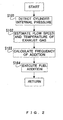
- control routine for performing the fuel addition control based on a flow chart shown in Fig. 2 .
- this routine is stored in the ECU 14 beforehand, and in this embodiment, the routine is executed in a periodic manner when the addition of fuel is executed at the time either of the cylinders 2 of the internal combustion engine 1 undergoes an exhaust stroke.
- step S101 the ECU 14 detects the internal pressure of one predetermined cylinder 2, for which a relevant exhaust valve 7 is opened, by means of a cylinder internal pressure sensor 11 at the time of opening of the relevant exhaust valve 7 for the one predetermined cylinder 2, which undergoes an exhaust stroke in the current fuel addition control of the internal combustion engine 1. That is, as shown in Fig. 3(a) , the cylinder internal pressure is detected at an instant immediately after the start of the exhaust stroke of the cylinder 2 for which the relevant exhaust valve 7 is opened.
- the ECU 14 executing this step corresponds to a cylinder internal pressure detection unit of the present invention. Then, the control flow shifts to step S102.
- step S102 based on the internal pressure of a cylinder 2 for which the relevant exhaust valve 7 is opened and which is detected by the relevant cylinder internal pressure sensor 11, the ECU 14 estimates the flow speed and the temperature of the exhaust gas passing the position of addition of fuel from the fuel addition valve 13 in the exhaust passage 9 for the period of the exhaust stroke of the cylinder 2 for which the relevant exhaust valve 7 is opened. That is, as shown in Fig. 3(b) , the flow speed of the exhaust gas, which changes in a convex curve, and the temperature of the exhaust gas, which changes in a straight line, are estimated in the period of the exhaust stroke of the cylinder 2 for which the relevant exhaust valve 7 is opened.
- the ECU 14 executing this step corresponds to an estimation unit of the present invention.
- the estimated flow speed and temperature of the exhaust gas is derived from a cylinder internal pressure map and the result of the last fuel addition control, and the higher the cylinder internal pressure, the greater the flow speed of the exhaust gas becomes, and the higher the temperature of the exhaust gas becomes.
- the flow speed of the exhaust gas is estimated in such a manner that a basic convex curve-shaped variation or fluctuation of the flow speed in the period of the exhaust stroke of one of the cylinders 2 is derived from the cylinder internal pressure map, and a starting point of the current flow speed is connected with a termination point of the flow speed estimated in the last fuel addition control.
- the temperature of the exhaust gas is estimated in such a manner that a first temperature of the exhaust gas at a time point when the flow speed of the exhaust gas in the current fuel addition control becomes maximum is derived from the cylinder internal pressure map, and the temperature of the exhaust gas changes linearly on a straight line connecting between the first temperature and a second temperature of the exhaust gas at a time point when the flow speed of the exhaust gas in the last fuel addition control became maximum. Thereafter, the control flow shifts to step S103.
- step S103 the ECU 14 calculates, based on the estimated flow speed and temperature of the exhaust gas, the frequency of addition of fuel from the fuel addition valve 13 for the period of the exhaust stroke of the cylinder 2 for which the relevant exhaust valve 7 is opened.
- the frequency of fuel addition thus calculated is derived from a map, which has the flow speed and the temperature of the exhaust gas as parameters, so as to provide an optimal amount of fuel addition, and the higher the flow speed and the temperature of the exhaust gas, the greater the frequency of fuel addition becomes, as shown in Fig. 3(c) .
- the ECU 14 executing this step corresponds to an addition control unit of the present invention. Then, the control flow shifts to step S104.
- step S104 the ECU 14 adds fuel from the fuel addition valve 13 to the exhaust gas at the frequency of fuel addition calculated in step S103.
- the timing of fuel addition is set to the time of starting the addition of fuel immediately after the flow speed of the exhaust gas changing in a convex curved manner, which was estimated in step S102, becomes maximum, as shown in Fig. 3(b) and (c) , in such a manner that the fuel to be added reaches the filter 12 at an optimal time while being entrained in the exhaust gas. Thereafter, the processing of this routine is once terminated.
- an optimal amount of fuel is added by increasing and decreasing the frequency of addition of fuel, but the present invention is not limited to this, and an optimal amount of fuel may be added by changing the duration of opening of the fuel addition valve 13 thereby to change the time or duration of fuel addition, or by changing the fuel addition pressure of the fuel addition valve 13 thereby to change the amount of fuel to be added per unit time.
- the time of fuel addition is uniquely decided as a time when the addition of fuel is started immediately after the estimated flow speed of the exhaust gas becomes maximum.
- the present invention is not limited to this, and the time of fuel addition may be appropriately changed in consideration of the flow speed and the temperature of the exhaust gas.
- the exhaust gas purification apparatus according to the present invention is not limited to the above-mentioned embodiment, but various changes may be made therein in the range not departing from the spirit of the present invention.
- an exhaust gas purification apparatus for an internal combustion engine it is possible to perform the addition of a reducing agent in a more appropriate manner.
Landscapes
- Engineering & Computer Science (AREA)
- Chemical & Material Sciences (AREA)
- Combustion & Propulsion (AREA)
- Mechanical Engineering (AREA)
- General Engineering & Computer Science (AREA)
- Chemical Kinetics & Catalysis (AREA)
- Health & Medical Sciences (AREA)
- Toxicology (AREA)
- Exhaust Gas After Treatment (AREA)
- Exhaust Gas Treatment By Means Of Catalyst (AREA)
- Treating Waste Gases (AREA)
Claims (2)
- Abgasreinigungsvorrichtung für einen Verbrennungsmotor, die eine an einer Abgasleitung des Verbrennungsmotors installierte Reduktionsmittel-Zugabeeinheit aufweist, die einem Abgas stromaufwärts von einer in der Abgasleitung angeordneen Abgasreinigungseinheit ein Reduktionsmittel zusetzt, wobei die Vorrichtung aufweist:eine Zylinderinnendruck-Erfassungseinheit, die beim Öffnen eines Abgasventils für einen Zylinder des Verbrennungsmotors einen Innendruck des Zylinders erfasst;eine Schätzeinheit, die auf Basis des Zylinderinnendrucks, der von der Zylinderinnendruck-Erfassungseinheit erfasst wird, eine Strömungsgeschwindigkeit oder eine Temperatur des Abgases schätzt, das an einer Reduktionsmittel-Zugabestelle der Reduktionsmittel-Zugabeeinheit in der Abgasleitung vorbei strömt; undeine Zugabesteuerungseinheit, die eine Zugabemenge des Reduktionsmittels auf Basis der von der Schätzeinheit geschätzten Strömungsgeschwindigkeit oder Temperatur des Abgases anpasst,wobei die Schätzeinheit den Zeitpunkt schätzt, zu dem die Strömungsgeschwindigkeit des pro Abgashubperiode ausgestoßenen Abgases am höchsten wird, undwobei die Zugabesteuereinheit den Zeitpunkt für die Zugabe des Reduktionsmittels auf Basis des von der Schätzeinheit geschätzten Zeitpunkts anpasst.
- Abgasreinigungsvorrichtung für einen Verbrennungsmotor nach Anspruch 1, wobei
die Schätzeinheit die Strömungsgeschwindigkeit oder die Temperatur des Abgases umso höher schätzt, je höher der von der Zylinderinnendruck-Erfassungseinheit erfasste Zylinderinnendruck ist; und
die Zugabesteuerungseinheit die Zugabemenge des Reduktionsmittels gemäß der von der Schätzeinheit geschätzten höheren Strömungsgeschwindigkeit oder Temperatur des Abgases anpasst.
Applications Claiming Priority (2)
| Application Number | Priority Date | Filing Date | Title |
|---|---|---|---|
| JP2006121613A JP4513779B2 (ja) | 2006-04-26 | 2006-04-26 | 内燃機関の排気浄化装置 |
| PCT/JP2007/059421 WO2007126131A1 (en) | 2006-04-26 | 2007-04-26 | Exhaust gas purification apparatus for an internal combustion engine |
Publications (2)
| Publication Number | Publication Date |
|---|---|
| EP2013454A1 EP2013454A1 (de) | 2009-01-14 |
| EP2013454B1 true EP2013454B1 (de) | 2010-07-21 |
Family
ID=38219023
Family Applications (1)
| Application Number | Title | Priority Date | Filing Date |
|---|---|---|---|
| EP07742856A Not-in-force EP2013454B1 (de) | 2006-04-26 | 2007-04-26 | Abgasreinigungsvorrichtung für einen verbrennungsmotor |
Country Status (6)
| Country | Link |
|---|---|
| US (1) | US20090229257A1 (de) |
| EP (1) | EP2013454B1 (de) |
| JP (1) | JP4513779B2 (de) |
| CN (1) | CN101427009B (de) |
| DE (1) | DE602007007929D1 (de) |
| WO (1) | WO2007126131A1 (de) |
Families Citing this family (8)
| Publication number | Priority date | Publication date | Assignee | Title |
|---|---|---|---|---|
| FR2929643B1 (fr) * | 2008-04-04 | 2010-06-04 | Faurecia Sys Echappement | Vaporisateur de gasoil |
| JP2011190778A (ja) * | 2010-03-16 | 2011-09-29 | Toyota Motor Corp | 内燃機関の制御装置 |
| GB2492355B (en) * | 2011-06-28 | 2017-01-11 | Gm Global Tech Operations Llc | Method for evaluating an exhaust gas temperature in a exhaust pipe of an internal combustion engine |
| JP5768767B2 (ja) * | 2012-06-19 | 2015-08-26 | トヨタ自動車株式会社 | 内燃機関の排気浄化装置 |
| CN108026811A (zh) * | 2015-07-24 | 2018-05-11 | Mtu 腓特烈港有限责任公司 | 用于将反应剂配给到内燃机的排气路径中的方法和内燃机 |
| WO2017104029A1 (ja) * | 2015-12-16 | 2017-06-22 | 株式会社 電子応用 | 燃焼状態推定装置 |
| JP6805021B2 (ja) * | 2017-02-21 | 2020-12-23 | 株式会社Soken | 燃料添加装置 |
| JP2019120239A (ja) * | 2018-01-11 | 2019-07-22 | 株式会社デンソー | 内燃機関の制御装置 |
Family Cites Families (17)
| Publication number | Priority date | Publication date | Assignee | Title |
|---|---|---|---|---|
| JPH08232743A (ja) * | 1995-02-27 | 1996-09-10 | Isuzu Motors Ltd | 排気ガス中のNOx 低減装置 |
| JP3282660B2 (ja) * | 1997-06-16 | 2002-05-20 | 本田技研工業株式会社 | 内燃機関の排気ガス浄化装置 |
| US6470673B1 (en) * | 2000-02-22 | 2002-10-29 | Ford Global Technologies, Inc. | Control of a NOX reductant delivery system |
| JP3508691B2 (ja) * | 2000-03-31 | 2004-03-22 | トヨタ自動車株式会社 | 内燃機関の排気浄化装置 |
| JP3632573B2 (ja) * | 2000-07-24 | 2005-03-23 | トヨタ自動車株式会社 | 内燃機関の排気浄化装置 |
| DE10124596B4 (de) * | 2001-05-21 | 2013-06-20 | Volkswagen Ag | Verfahren und Vorrichtungen zur Bestimmung der Gasaustrittstemperatur oder Gaseintrittstemperatur eines Verbrennungsmotors |
| US6679200B2 (en) * | 2002-06-11 | 2004-01-20 | Delphi Technologies, Inc. | Direct in-cylinder reductant injection system and a method of implementing same |
| US20040093856A1 (en) * | 2002-11-18 | 2004-05-20 | Dingle Philip J. G. | Apparatus and method for reductant dosing of an exhaust |
| JP4165236B2 (ja) * | 2003-01-28 | 2008-10-15 | トヨタ自動車株式会社 | 内燃機関の排気状態検出装置 |
| CA2441686C (en) * | 2003-09-23 | 2004-12-21 | Westport Research Inc. | Method for controlling combustion in an internal combustion engine and predicting performance and emissions |
| JP3903977B2 (ja) * | 2003-10-17 | 2007-04-11 | トヨタ自動車株式会社 | 内燃機関の排気浄化装置及び内燃機関の排気浄化方法 |
| DE102004001118B4 (de) * | 2004-01-07 | 2018-08-23 | Robert Bosch Gmbh | Verfahren und Vorrichtung zur Steuerung einer Brennkraftmaschine |
| US20050252201A1 (en) * | 2004-05-17 | 2005-11-17 | Lecea Oscar A | Method and apparatus for reducing NOx emissions |
| JP4204519B2 (ja) * | 2004-06-14 | 2009-01-07 | トヨタ自動車株式会社 | 内燃機関の排気浄化装置 |
| JP2007023807A (ja) * | 2005-07-12 | 2007-02-01 | Toyota Motor Corp | エンジンの排気浄化装置 |
| FR2891868B1 (fr) * | 2005-10-07 | 2007-12-21 | Renault Sas | Procede d'estimation de la temperature d'echappement d'un moteur, et procede de diagnostic d'un capteur de pression cylindre utilisant une estimation de la temperature d'echappement. |
| US7886528B2 (en) * | 2008-02-29 | 2011-02-15 | Perkins Engines Company Limited | System for controlling exhaust aftertreatment |
-
2006
- 2006-04-26 JP JP2006121613A patent/JP4513779B2/ja not_active Expired - Fee Related
-
2007
- 2007-04-26 CN CN2007800144839A patent/CN101427009B/zh not_active Expired - Fee Related
- 2007-04-26 US US12/226,611 patent/US20090229257A1/en not_active Abandoned
- 2007-04-26 EP EP07742856A patent/EP2013454B1/de not_active Not-in-force
- 2007-04-26 DE DE602007007929T patent/DE602007007929D1/de active Active
- 2007-04-26 WO PCT/JP2007/059421 patent/WO2007126131A1/en not_active Ceased
Also Published As
| Publication number | Publication date |
|---|---|
| CN101427009A (zh) | 2009-05-06 |
| US20090229257A1 (en) | 2009-09-17 |
| JP2007291969A (ja) | 2007-11-08 |
| JP4513779B2 (ja) | 2010-07-28 |
| WO2007126131A1 (en) | 2007-11-08 |
| DE602007007929D1 (de) | 2010-09-02 |
| EP2013454A1 (de) | 2009-01-14 |
| CN101427009B (zh) | 2010-12-15 |
Similar Documents
| Publication | Publication Date | Title |
|---|---|---|
| EP2013454B1 (de) | Abgasreinigungsvorrichtung für einen verbrennungsmotor | |
| EP1905991B1 (de) | Steuerverfahren für abgasreinigungssystem und abgasreinigungssystem | |
| US6966178B2 (en) | Internal combustion engine exhaust gas purification system | |
| EP2218884A1 (de) | Abgasnachverarbeitungsvorrichtung | |
| US7578123B2 (en) | Exhaust cleaning device of diesel engine | |
| EP3025033B1 (de) | Abgasemissionssteuerungssystem für einen verbrennungsmotor und steuerungsverfahren für das abgasemissionssteuerungssystem | |
| US7980060B2 (en) | Filter clogging determination apparatus for diesel engine | |
| WO2010133276A1 (en) | Method for calculating an efficiency index of a diesel oxidation catalyst | |
| EP1778954B1 (de) | Abgasreinigungsvorrichtung und abgasreinigungsverfahren für verbrennungsmotor | |
| US7162867B2 (en) | Exhaust gas purifying device for internal combustion engine | |
| US20090007549A1 (en) | Method Of Controlling Exhaust Gas Purification System And Exhaust Gas Purification System | |
| EP2034165B1 (de) | Steuerverfahren für abgasreinigungssystem und abgasreinigungssystem | |
| US8627652B2 (en) | Control method of exhaust gas purification system and exhaust gas purification system | |
| US8601793B2 (en) | Malfunction diagnostic device for exhaust gas control device | |
| JP2014222028A (ja) | Pm堆積量推定装置および内燃機関の排気浄化システム | |
| JP2005240719A (ja) | フィルタの再生時期検出装置およびフィルタの再生制御装置 | |
| JP2009013889A (ja) | 内燃機関の燃料制御装置 | |
| JP5093093B2 (ja) | 内燃機関の異常判定装置 | |
| JP2019116876A (ja) | センサ診断システム | |
| JP4697463B2 (ja) | エンジンオイルの希釈状態推定装置 | |
| JP4849823B2 (ja) | パティキュレートフィルタの再生制御装置 | |
| JP2020051405A (ja) | 内燃機関の診断装置 | |
| JP2008121573A (ja) | 内燃機関の排気浄化装置 | |
| JP2019039400A (ja) | 内燃機関の排気ガス流量測定装置 | |
| JP2019039399A (ja) | 内燃機関の排気浄化装置 |
Legal Events
| Date | Code | Title | Description |
|---|---|---|---|
| PUAI | Public reference made under article 153(3) epc to a published international application that has entered the european phase |
Free format text: ORIGINAL CODE: 0009012 |
|
| 17P | Request for examination filed |
Effective date: 20081126 |
|
| AK | Designated contracting states |
Kind code of ref document: A1 Designated state(s): AT BE BG CH CY CZ DE DK EE ES FI FR GB GR HU IE IS IT LI LT LU LV MC MT NL PL PT RO SE SI SK TR |
|
| AX | Request for extension of the european patent |
Extension state: AL BA HR MK RS |
|
| DAX | Request for extension of the european patent (deleted) | ||
| RBV | Designated contracting states (corrected) |
Designated state(s): DE FR GB |
|
| 17Q | First examination report despatched |
Effective date: 20090929 |
|
| GRAP | Despatch of communication of intention to grant a patent |
Free format text: ORIGINAL CODE: EPIDOSNIGR1 |
|
| GRAS | Grant fee paid |
Free format text: ORIGINAL CODE: EPIDOSNIGR3 |
|
| GRAA | (expected) grant |
Free format text: ORIGINAL CODE: 0009210 |
|
| AK | Designated contracting states |
Kind code of ref document: B1 Designated state(s): DE FR GB |
|
| REG | Reference to a national code |
Ref country code: GB Ref legal event code: FG4D |
|
| REF | Corresponds to: |
Ref document number: 602007007929 Country of ref document: DE Date of ref document: 20100902 Kind code of ref document: P |
|
| PLBE | No opposition filed within time limit |
Free format text: ORIGINAL CODE: 0009261 |
|
| STAA | Information on the status of an ep patent application or granted ep patent |
Free format text: STATUS: NO OPPOSITION FILED WITHIN TIME LIMIT |
|
| 26N | No opposition filed |
Effective date: 20110426 |
|
| REG | Reference to a national code |
Ref country code: DE Ref legal event code: R097 Ref document number: 602007007929 Country of ref document: DE Effective date: 20110426 |
|
| REG | Reference to a national code |
Ref country code: GB Ref legal event code: 746 Effective date: 20130128 |
|
| REG | Reference to a national code |
Ref country code: DE Ref legal event code: R084 Ref document number: 602007007929 Country of ref document: DE Effective date: 20130125 |
|
| PGFP | Annual fee paid to national office [announced via postgrant information from national office to epo] |
Ref country code: GB Payment date: 20130424 Year of fee payment: 7 Ref country code: DE Payment date: 20130508 Year of fee payment: 7 |
|
| PGFP | Annual fee paid to national office [announced via postgrant information from national office to epo] |
Ref country code: FR Payment date: 20130625 Year of fee payment: 7 |
|
| REG | Reference to a national code |
Ref country code: DE Ref legal event code: R119 Ref document number: 602007007929 Country of ref document: DE |
|
| GBPC | Gb: european patent ceased through non-payment of renewal fee |
Effective date: 20140426 |
|
| REG | Reference to a national code |
Ref country code: DE Ref legal event code: R119 Ref document number: 602007007929 Country of ref document: DE Effective date: 20141101 |
|
| REG | Reference to a national code |
Ref country code: FR Ref legal event code: ST Effective date: 20141231 |
|
| PG25 | Lapsed in a contracting state [announced via postgrant information from national office to epo] |
Ref country code: GB Free format text: LAPSE BECAUSE OF NON-PAYMENT OF DUE FEES Effective date: 20140426 Ref country code: DE Free format text: LAPSE BECAUSE OF NON-PAYMENT OF DUE FEES Effective date: 20141101 |
|
| PG25 | Lapsed in a contracting state [announced via postgrant information from national office to epo] |
Ref country code: FR Free format text: LAPSE BECAUSE OF NON-PAYMENT OF DUE FEES Effective date: 20140430 |