EP2013471B1 - Dispositif de refoulement de carburant sous haute pression - Google Patents
Dispositif de refoulement de carburant sous haute pression Download PDFInfo
- Publication number
- EP2013471B1 EP2013471B1 EP07726366A EP07726366A EP2013471B1 EP 2013471 B1 EP2013471 B1 EP 2013471B1 EP 07726366 A EP07726366 A EP 07726366A EP 07726366 A EP07726366 A EP 07726366A EP 2013471 B1 EP2013471 B1 EP 2013471B1
- Authority
- EP
- European Patent Office
- Prior art keywords
- pressure
- flow path
- delivery device
- fuel delivery
- pump
- Prior art date
- Legal status (The legal status is an assumption and is not a legal conclusion. Google has not performed a legal analysis and makes no representation as to the accuracy of the status listed.)
- Not-in-force
Links
- 239000000446 fuel Substances 0.000 title claims abstract description 102
- 238000002485 combustion reaction Methods 0.000 claims abstract description 11
- 230000001050 lubricating effect Effects 0.000 claims abstract description 6
- 238000011144 upstream manufacturing Methods 0.000 claims description 4
- 239000002828 fuel tank Substances 0.000 description 7
- 238000011161 development Methods 0.000 description 3
- 230000018109 developmental process Effects 0.000 description 3
- 238000005461 lubrication Methods 0.000 description 3
- 238000010276 construction Methods 0.000 description 2
- 230000000694 effects Effects 0.000 description 1
- 238000000605 extraction Methods 0.000 description 1
- 239000003502 gasoline Substances 0.000 description 1
- 238000010438 heat treatment Methods 0.000 description 1
- 239000007788 liquid Substances 0.000 description 1
- 238000012423 maintenance Methods 0.000 description 1
- 238000004519 manufacturing process Methods 0.000 description 1
Images
Classifications
-
- F—MECHANICAL ENGINEERING; LIGHTING; HEATING; WEAPONS; BLASTING
- F02—COMBUSTION ENGINES; HOT-GAS OR COMBUSTION-PRODUCT ENGINE PLANTS
- F02M—SUPPLYING COMBUSTION ENGINES IN GENERAL WITH COMBUSTIBLE MIXTURES OR CONSTITUENTS THEREOF
- F02M59/00—Pumps specially adapted for fuel-injection and not provided for in groups F02M39/00 -F02M57/00, e.g. rotary cylinder-block type of pumps
- F02M59/44—Details, components parts, or accessories not provided for in, or of interest apart from, the apparatus of groups F02M59/02 - F02M59/42; Pumps having transducers, e.g. to measure displacement of pump rack or piston
-
- F—MECHANICAL ENGINEERING; LIGHTING; HEATING; WEAPONS; BLASTING
- F02—COMBUSTION ENGINES; HOT-GAS OR COMBUSTION-PRODUCT ENGINE PLANTS
- F02M—SUPPLYING COMBUSTION ENGINES IN GENERAL WITH COMBUSTIBLE MIXTURES OR CONSTITUENTS THEREOF
- F02M59/00—Pumps specially adapted for fuel-injection and not provided for in groups F02M39/00 -F02M57/00, e.g. rotary cylinder-block type of pumps
- F02M59/20—Varying fuel delivery in quantity or timing
- F02M59/34—Varying fuel delivery in quantity or timing by throttling of passages to pumping elements or of overflow passages, e.g. throttling by means of a pressure-controlled sliding valve having liquid stop or abutment
-
- F—MECHANICAL ENGINEERING; LIGHTING; HEATING; WEAPONS; BLASTING
- F02—COMBUSTION ENGINES; HOT-GAS OR COMBUSTION-PRODUCT ENGINE PLANTS
- F02M—SUPPLYING COMBUSTION ENGINES IN GENERAL WITH COMBUSTIBLE MIXTURES OR CONSTITUENTS THEREOF
- F02M63/00—Other fuel-injection apparatus having pertinent characteristics not provided for in groups F02M39/00 - F02M57/00 or F02M67/00; Details, component parts, or accessories of fuel-injection apparatus, not provided for in, or of interest apart from, the apparatus of groups F02M39/00 - F02M61/00 or F02M67/00; Combination of fuel pump with other devices, e.g. lubricating oil pump
- F02M63/0001—Fuel-injection apparatus with specially arranged lubricating system, e.g. by fuel oil
-
- F—MECHANICAL ENGINEERING; LIGHTING; HEATING; WEAPONS; BLASTING
- F02—COMBUSTION ENGINES; HOT-GAS OR COMBUSTION-PRODUCT ENGINE PLANTS
- F02M—SUPPLYING COMBUSTION ENGINES IN GENERAL WITH COMBUSTIBLE MIXTURES OR CONSTITUENTS THEREOF
- F02M63/00—Other fuel-injection apparatus having pertinent characteristics not provided for in groups F02M39/00 - F02M57/00 or F02M67/00; Details, component parts, or accessories of fuel-injection apparatus, not provided for in, or of interest apart from, the apparatus of groups F02M39/00 - F02M61/00 or F02M67/00; Combination of fuel pump with other devices, e.g. lubricating oil pump
- F02M63/02—Fuel-injection apparatus having several injectors fed by a common pumping element, or having several pumping elements feeding a common injector; Fuel-injection apparatus having provisions for cutting-out pumps, pumping elements, or injectors; Fuel-injection apparatus having provisions for variably interconnecting pumping elements and injectors alternatively
- F02M63/0225—Fuel-injection apparatus having a common rail feeding several injectors ; Means for varying pressure in common rails; Pumps feeding common rails
- F02M63/0275—Arrangement of common rails
- F02M63/028—Returnless common rail system
-
- F—MECHANICAL ENGINEERING; LIGHTING; HEATING; WEAPONS; BLASTING
- F02—COMBUSTION ENGINES; HOT-GAS OR COMBUSTION-PRODUCT ENGINE PLANTS
- F02M—SUPPLYING COMBUSTION ENGINES IN GENERAL WITH COMBUSTIBLE MIXTURES OR CONSTITUENTS THEREOF
- F02M63/00—Other fuel-injection apparatus having pertinent characteristics not provided for in groups F02M39/00 - F02M57/00 or F02M67/00; Details, component parts, or accessories of fuel-injection apparatus, not provided for in, or of interest apart from, the apparatus of groups F02M39/00 - F02M61/00 or F02M67/00; Combination of fuel pump with other devices, e.g. lubricating oil pump
- F02M63/02—Fuel-injection apparatus having several injectors fed by a common pumping element, or having several pumping elements feeding a common injector; Fuel-injection apparatus having provisions for cutting-out pumps, pumping elements, or injectors; Fuel-injection apparatus having provisions for variably interconnecting pumping elements and injectors alternatively
- F02M63/0225—Fuel-injection apparatus having a common rail feeding several injectors ; Means for varying pressure in common rails; Pumps feeding common rails
Definitions
- the invention relates to a high-pressure fuel delivery device according to the preamble of claim 1.
- Such a fuel high-pressure conveyor for an internal combustion engine is characterized by the WO 02/40857 A known.
- This high-pressure fuel delivery device has a high-pressure pump and a low-pressure flow path that leads from a fuel inlet of the high-pressure fuel delivery device to a receiving space for a drive shaft of the high-pressure pump and to at least one inlet valve of the high-pressure pump.
- a return flow path is provided, is returned via the leakage and / or lubricating fuel.
- the return flow path leads out of the high pressure pump and flows into a return line to a tank and thus into a low pressure flow path. At least one further connection for the return flow path is thus required in addition to the fuel inlet at the high-pressure fuel delivery device, which leads to a complicated construction of the high-pressure fuel delivery device.
- a high-pressure fuel conveyor in the form of a high-pressure pump is known, in which the high-pressure pump is shown only symbolically.
- the high pressure pump does not have a return flow path for leakage and / or lubricating fuel. How a required lubrication of the high pressure pump is not specified here. From a connection between the high-pressure pump and a fuel reservoir performs a return flow path, which opens into a low-pressure flow path to the high-pressure pump. Both the return flow path and the low-pressure flow path are arranged outside the high-pressure pump.
- the present invention has the object, a high-pressure fuel conveyor of the to provide the aforementioned type, which allows a cheaper construction of the fuel system.
- the return flow path does not leave the high-pressure fuel delivery device, but is integrated into it.
- the fuel passing through, for example, the shaft bearings and / or shaft seals of the drive shaft is not returned to the tank but remains within the high pressure fuel delivery by being introduced into the low pressure flow path. In this way, an undesirable heating of the fuel stored in the fuel tank is avoided.
- An advantageous embodiment of the fuel high-pressure conveyor according to the invention is characterized in that it comprises an integrated prefeed pump. This creates a particularly compact and powerful high-pressure fuel delivery device.
- the prefeed pump is arranged in the low-pressure flow path, and that the return flow path upstream of the prefeed pump in the low pressure flow path opens.
- a fuel system with such designed high-pressure fuel delivery device is particularly simple and compact.
- a mechanical pressure control valve may be provided with a return channel, which opens into the low-pressure flow path upstream of the prefeed pump.
- a return channel which opens into the low-pressure flow path upstream of the prefeed pump.
- the high-pressure fuel delivery device can be connected to an external feed pump.
- an external feed pump Such may, for example, be provided in the region of the tank of the fuel system to which the high-pressure fuel delivery device belongs. In this way it is avoided that a fuel line with comparatively low pressure is present between the high-pressure fuel conveyor and the tank, in which, for example, vapor bubbles can form.
- a particularly advantageous development of the high-pressure fuel delivery device is characterized in that a suction jet pump is arranged in the low-pressure flow path, which is driven by the fuel flowing to the inlet valve and into which the return flow path opens.
- the passing through the shaft bearings for example, amount of fuel is sucked in this way by the suction jet pump.
- the sum of the amount of fuel flowing directly from the receiving space to the intake valve and the amount of flow recirculated via the return flow path is then available as a high-pressure delivery quantity.
- Such a high-pressure fuel delivery device has a good efficiency, and moreover, the lubrication of the bearings is improved by the forced extraction of the lubricating fuel.
- an external prefeed pump is provided, with which the fuel high-pressure conveyor is connectable, the return of the lubricating fuel is ensured even at low speeds of the high pressure pump by such a suction jet pump.
- the adjustment of the prefeed pressure that is, the pressure with which the fuel through the receiving space to the intake valve is promoted, be particularly well adjusted.
- a particularly compact high-pressure fuel delivery device can be created.
- an adjustable throttle device may be disposed downstream of the mouth of the return flow path.
- metering unit allows adjustment of the delivery of the high-pressure pump and thus the high-pressure fuel conveyor.
- At least one flow restrictor may be arranged in the return flow path.
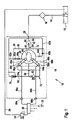
- a fuel system carries the overall reference numeral 10. It belongs to an internal combustion engine, not shown, which in turn drives a motor vehicle, not shown.
- the fuel system 10 includes a fuel tank 12 in which a liquid fuel, such as gasoline or diesel, is stored. From the fuel tank 12, a fuel line 14 via a filter 16 to a high-pressure fuel conveyor 18. In this, the fuel is compressed to a high pressure and conveyed to a fuel pressure accumulator 20, which is also referred to as "rail". To the rail 20 a plurality of fuel injectors 22 are connected, which inject the fuel directly into them associated combustion chambers (not shown) of the internal combustion engine. To the rail 20, a controllable pressure relief valve 24 is connected, from which a drain line 26 leads back to the fuel tank 12.
- a liquid fuel such as gasoline or diesel
- the high-pressure fuel delivery device 18 includes a fuel inlet 28 to which the fuel line 14 is connected. From the fuel inlet 28, a channel 30 leads to a prefeed pump 32, which is integrated into the high-pressure fuel delivery device 18. From the prefeed pump 32, a channel 34 leads to a high-pressure pump 36.
- the high-pressure pump 36 as well as the prefeed pump 32 is mechanically driven by the internal combustion engine, for example by a camshaft of the internal combustion engine.
- the high pressure pump 36 comprises a housing 38 having a receiving space 40 for a provided with a cam 42 drive shaft 44. This works with two pistons 46 a and 46 b together, the delivery spaces 48 a and 48 b limit.
- a channel 50 leads to an adjustable throttling device 52, from which in turn pass channels 54a and 54b via intake valves 56a and 56b to the delivery chambers 48a and 48b.
- Channels 58a and 58b connect delivery chambers 48a and 48b to exhaust valves 60a and 60b. These simultaneously form a fuel outlet of the high-pressure fuel delivery device, to which the rail 20 is connected.
- the drive shaft 44 is mounted in the housing 38 of the high-pressure pump 36 by shaft bearings.
- the receiving space 40 is sealed to the outside via corresponding shaft seals.
- These are not absolutely tight and therefore in FIG. 1 by channels 62a and 62b and corresponding throttles 64a and 64b.
- the throttle or shaft seal 64a is arranged in a housing cover, the throttle or shaft seal 64b in a housing body. About limiting throttles 65a and 65b lead the channels 62a and 62b back to the channel 30.
- the mouth is designated 66.
- an overflow channel 68 branches off, in which a mechanical pressure control or overflow valve 70 is arranged.
- the overflow channel 68 opens into the channel 62 a and thus ultimately into the channel 30 at 66.
- the fuel is sucked in by the prefeed pump 32 from the fuel tank 12 and compressed to a comparatively low prefeed pressure, for example 4 bar, and conveyed into the receiving space 40 at this pressure. There it serves to cool and lubricate the bearings of the drive shaft 44. From the receiving space 40, the fuel flows via the adjustable throttle 52 to the intake valves 56a, b and on into the delivery chambers 48a, b, where it is compressed and via the outlet valves 60a, b for Rail 20 is promoted.
- a comparatively low prefeed pressure for example 4 bar
- the fuel which passes through for the lubrication of the bearings of the drive shaft 44 and via the shaft seals 64a, b is conveyed via the return flow path 62a, b to the suction side (channel 30) of the prefeed pump 32 and sucked back therefrom.
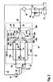
- FIG. 2 A fuel system 10 with an alternative embodiment of a high pressure fuel delivery device 18 is shown in FIG FIG. 2 shown. It is true that such elements and areas that have equivalent functions to previously described elements and areas, the same reference numerals and are not explained in detail again.
- the prefeed pump 32 is not integrated into the high-pressure fuel conveyor 18, but arranged as an external prefeed pump 32 in the region of the fuel tank 12. It is also not powered by the internal combustion engine, but electrically.
- the pressure control valve 70 with the overflow channel 68 is arranged in the region of the prefeed pump 32 close to the fuel tank 12.
- an ejector 74 is arranged in the channel 50, which leads from the receiving space 40 via the adjustable throttle 52 to the channels 54a, b and on to the inlet valves 56a, b. This is thus driven by the fuel flowing from the receiving space 40 to the inlet valves 56a, b, and in 66 opens the return flow path 62a, b.
Landscapes
- Engineering & Computer Science (AREA)
- Chemical & Material Sciences (AREA)
- Combustion & Propulsion (AREA)
- Mechanical Engineering (AREA)
- General Engineering & Computer Science (AREA)
- Fuel-Injection Apparatus (AREA)
Claims (11)
- Dispositif de refoulement de carburant sous haute pression (18) pour un moteur à combustion interne, dans lequel le dispositif de refoulement de carburant sous haute pression (18) comprend au moins une pompe haute pression (36) et des voies d'écoulement (30, 34, 40, 50, 58a, 72), à travers lesquelles du carburant parvient depuis une entrée de carburant (28) du dispositif de refoulement de carburant sous haute pression (18) jusqu'à une sortie de carburant (60a, 60b) du dispositif de refoulement de carburant sous haute pression (18), les voies d'écoulement (30, 34, 40, 50, 58a, 58b, 72) comprenant une voie d'écoulement basse pression (72) qui conduit depuis une entrée de carburant (28) du dispositif de refoulement de carburant sous haute pression (18) jusqu'à un espace de réception (40) pour un arbre d'entraînement (44) de la pompe haute pression (36) et jusqu'à au moins une soupape d'admission (56) de la pompe haute pression (36), et comprenant une voie d'écoulement de retour (62), par le biais de laquelle du carburant de fuite et/ou de lubrification est ramené, la voie d'écoulement de retour (62) débouchant dans la voie d'écoulement basse pression (72), caractérisé en ce que la voie d'écoulement basse pression (72) conduit jusqu'à l'espace de réception (40) et ensuite jusqu'à l'au moins une soupape d'admission (56), en ce que la voie d'écoulement de retour (62) est intégrée dans le dispositif de refoulement de carburant sous haute pression (18) et ne quitte pas ce dernier, et en ce que la voie d'écoulement de retour (62) débouche (66) à l'intérieur du dispositif de refoulement de carburant sous haute pression (18) dans la voie d'écoulement basse pression (72).
- Dispositif de refoulement de carburant sous haute pression (18) selon la revendication 1, caractérisé en ce qu'il comprend une pompe de pré-refoulement intégrée (32).
- Dispositif de refoulement de carburant sous haute pression (18) selon la revendication 2, caractérisé en ce que la pompe de pré-refoulement (32) est disposée dans la voie d'écoulement basse pression (72), et en ce que la voie d'écoulement de retour (62) débouche (66) en aval de la pompe de pré-refoulement (32) dans la voie d'écoulement basse pression (72).
- Dispositif de refoulement de carburant sous haute pression (18) selon l'une quelconque des revendications 2 ou 3, caractérisé en ce qu'il comprend une soupape de régulation de la pression mécanique (70) avec un canal de trop-plein (68) qui débouche en aval de la pompe de pré-refoulement (32) dans la voie d'écoulement basse pression (72).
- Dispositif de refoulement de carburant sous haute pression (18) selon la revendication 1, caractérisé en ce qu'il peut être connecté à une pompe de pré-refoulement externe (32).
- Dispositif de refoulement de carburant sous haute pression (18) selon la revendication 5, caractérisé en ce que la voie d'écoulement de retour (62) débouche (66) entre l'espace de réception (40) et la soupape d'admission (56) dans la voie d'écoulement basse pression (72).
- Dispositif de refoulement de carburant sous haute pression (18) selon l'une quelconque des revendications précédentes, caractérisé en ce qu'une pompe à jet aspirant (74) est disposée dans la voie d'écoulement basse pression (72), laquelle est entraînée par le carburant s'écoulant jusqu'à la soupape d'admission (56) et dans laquelle débouche (66) la voie d'écoulement de retour (62).
- Dispositif de refoulement de carburant sous haute pression (18) selon l'une quelconque des revendications 2 à 7, caractérisé en ce que la pompe de pré-refoulement (32) est entraînée de manière électrique.
- Dispositif de refoulement de carburant sous haute pression (18) selon l'une quelconque des revendications 2 à 7, caractérisé en ce que la pompe de pré-refoulement (32) est entraînée au moins indirectement par le moteur à combustion interne.
- Dispositif de refoulement de carburant sous haute pression (18) selon l'une quelconque des revendications précédentes, caractérisé en ce qu'un dispositif d'étranglement réglable (52) est disposé dans la voie d'écoulement basse pression (72) en aval de l'embouchure (66) de la voie d'écoulement de retour (62).
- Dispositif de refoulement de carburant sous haute pression (18) selon l'une quelconque des revendications précédentes, caractérisé en ce qu'au moins un étranglement d'écoulement (65) est disposé dans la voie d'écoulement de retour (62).
Applications Claiming Priority (2)
| Application Number | Priority Date | Filing Date | Title |
|---|---|---|---|
| DE102006018702A DE102006018702A1 (de) | 2006-04-21 | 2006-04-21 | Kraftstoff-Hochdruck-Fördereinrichtung |
| PCT/EP2007/051410 WO2007122023A1 (fr) | 2006-04-21 | 2007-02-14 | Dispositif de refoulement de carburant sous haute pression |
Publications (2)
| Publication Number | Publication Date |
|---|---|
| EP2013471A1 EP2013471A1 (fr) | 2009-01-14 |
| EP2013471B1 true EP2013471B1 (fr) | 2011-11-30 |
Family
ID=37965025
Family Applications (1)
| Application Number | Title | Priority Date | Filing Date |
|---|---|---|---|
| EP07726366A Not-in-force EP2013471B1 (fr) | 2006-04-21 | 2007-02-14 | Dispositif de refoulement de carburant sous haute pression |
Country Status (6)
| Country | Link |
|---|---|
| EP (1) | EP2013471B1 (fr) |
| CN (1) | CN101427020A (fr) |
| AT (1) | ATE535707T1 (fr) |
| BR (1) | BRPI0706557A2 (fr) |
| DE (1) | DE102006018702A1 (fr) |
| WO (1) | WO2007122023A1 (fr) |
Families Citing this family (12)
| Publication number | Priority date | Publication date | Assignee | Title |
|---|---|---|---|---|
| DE102008017222A1 (de) * | 2008-04-04 | 2009-10-08 | Continental Automotive Gmbh | Pumpenanordnung zur Förderung eines Fluids |
| DE102008001704A1 (de) | 2008-05-09 | 2009-11-12 | Robert Bosch Gmbh | Kraftstofffördereinrichtung |
| DE102010026159A1 (de) * | 2010-07-06 | 2012-01-12 | Audi Ag | Kraftstoffsystem für eine Brennkraftmaschine |
| DE102010042587A1 (de) * | 2010-10-18 | 2012-04-19 | Robert Bosch Gmbh | Kraftstoffpumpe für ein Kraftstoffeinspritzsystem einer Brennkraftmaschine |
| DE102011003089A1 (de) | 2011-01-25 | 2012-07-26 | Robert Bosch Gmbh | Überströmventil eines Krafteinspritzsystems |
| DE102011075474A1 (de) | 2011-05-09 | 2012-11-15 | Robert Bosch Gmbh | Hochdruckpumpe |
| DE102011089623A1 (de) | 2011-12-22 | 2013-06-27 | Robert Bosch Gmbh | Kraftstofffördereinrichtung für ein Kraftstoffeinspritzsystem sowie Kraftstoffeinspritzsystem |
| DE102012203724A1 (de) | 2012-03-09 | 2013-09-12 | Robert Bosch Gmbh | Kraftstofffördereinrichtung für ein Kraftstoffeinspritzsystem mit einem Überströmventil sowie Überströmventil |
| DE102012210177A1 (de) | 2012-06-18 | 2013-12-19 | Robert Bosch Gmbh | Kraftstofffördereinrichtung für ein Kraftstoffeinspritzsystem sowie Kraftstoffeinspritzsystem |
| DE102012212062A1 (de) | 2012-07-11 | 2014-01-16 | Robert Bosch Gmbh | Niederdruckkreislauf für ein Kraftstoffeinspritzsystem, Kraftstoffeinspritzsystem sowie Verfahren zum Betreiben eines Kraftstoffeinspritzsystems |
| DE102015217863A1 (de) * | 2015-09-17 | 2017-03-23 | Continental Automotive Gmbh | Kraftstoffeinspritzsystem |
| EP3601777B1 (fr) * | 2017-03-29 | 2021-10-27 | Wärtsilä Finland Oy | Ensemble pompe à carburant haute pression pour moteur à piston à combustion interne |
Family Cites Families (5)
| Publication number | Priority date | Publication date | Assignee | Title |
|---|---|---|---|---|
| DE19714488C1 (de) | 1997-04-08 | 1998-09-03 | Siemens Ag | Verfahren zum Erwärmen von Kraftstoff und Kraftstoffeinspritzanlage |
| DE19941689A1 (de) * | 1999-09-01 | 2001-03-15 | Siemens Ag | Einspritzanlage für eine Brennkraftmaschine |
| DE10057244A1 (de) | 2000-11-18 | 2002-06-06 | Bosch Gmbh Robert | Kraftstoffeinspritzanlage für Brennkraftmaschinen mit verbessertem Startverhalten |
| DE10205187A1 (de) * | 2002-02-08 | 2003-08-21 | Bosch Gmbh Robert | Kraftstoffeinspritzeinrichtung für eine Brennkraftmaschine |
| JP3915718B2 (ja) * | 2003-03-11 | 2007-05-16 | 株式会社デンソー | 燃料供給ポンプ |
-
2006
- 2006-04-21 DE DE102006018702A patent/DE102006018702A1/de not_active Withdrawn
-
2007
- 2007-02-14 CN CNA2007800143041A patent/CN101427020A/zh active Pending
- 2007-02-14 WO PCT/EP2007/051410 patent/WO2007122023A1/fr not_active Ceased
- 2007-02-14 EP EP07726366A patent/EP2013471B1/fr not_active Not-in-force
- 2007-02-14 AT AT07726366T patent/ATE535707T1/de active
- 2007-02-14 BR BRPI0706557-4A patent/BRPI0706557A2/pt not_active IP Right Cessation
Also Published As
| Publication number | Publication date |
|---|---|
| DE102006018702A1 (de) | 2007-10-25 |
| BRPI0706557A2 (pt) | 2011-03-29 |
| ATE535707T1 (de) | 2011-12-15 |
| WO2007122023A1 (fr) | 2007-11-01 |
| EP2013471A1 (fr) | 2009-01-14 |
| CN101427020A (zh) | 2009-05-06 |
Similar Documents
| Publication | Publication Date | Title |
|---|---|---|
| EP2013471B1 (fr) | Dispositif de refoulement de carburant sous haute pression | |
| EP2032832B1 (fr) | Dispositif d'injection de carburant pour un moteur à combustion interne | |
| EP2591225B1 (fr) | Système de carburant pour un moteur à combustion interne | |
| EP1190174B1 (fr) | Systeme de pompe pour l'alimentation en carburant | |
| EP1702157B1 (fr) | Systeme d'injection de carburant pour un moteur a combustion interne | |
| WO2003067072A9 (fr) | Dispositif d'injection de carburant pour moteur a combustion interne | |
| DE102007000855A1 (de) | Kraftstofffördergerät und Speicherkraftstoffeinspritzsystem, das dieses aufweist | |
| DE10136399A1 (de) | Kraftstoff-Strahlpumpe für Kraftfahrzeuge | |
| DE3235413A1 (de) | Brennstoffeinspritzvorrichtung | |
| EP2640958B1 (fr) | Circuit basse pression pour un système d'injection de carburant et système d'injection de carburant | |
| DE102009044866B4 (de) | Kraftstoffversorgungssystem für eine Verbrennungskraftmaschine | |
| WO2010012525A1 (fr) | Dispositif d'alimentation en carburant pour moteur à combustion interne | |
| DE102015219417B3 (de) | Kraftstoffhochdruckpumpe sowie Kraftstoffversorgungseinrichtung für eine Verbrennungskraftmaschine, insbesondere eines Kraftwagens | |
| DE10154133C1 (de) | Kraftstoffsystem | |
| EP1262658B1 (fr) | Système de combustible pour amener du combustible pour un moteur à combustion interne | |
| DE10237586A1 (de) | Kraftstoffeinspritzeinrichtung für eine Brennkraftmaschine | |
| EP1394403B1 (fr) | Système de combustible pour un moteur à combustion interne | |
| DE102017211826B3 (de) | Vorrichtung zur Einspritzung von Wasser für eine Verbrennungskraftmaschine | |
| DE102007056418A1 (de) | Einspritzanlage für eine Brennkraftmaschine | |
| WO2009121823A1 (fr) | Système de pompe de transport de fluide | |
| EP1298316B1 (fr) | Système d'injection de carburant | |
| DE10134068A1 (de) | Brennkraftmaschine, insbesondere für Kraftfahrzeuge | |
| WO2005038236A1 (fr) | Systeme d'injection de carburant pour un moteur a combustion interne | |
| DE102009047488A1 (de) | Kraftstoffeinspritzeinrichtung für eine Brennkraftmaschine | |
| DE10129437A1 (de) | Kraftstoffversorgungseinrichtung für ein Kraftfahrzeug |
Legal Events
| Date | Code | Title | Description |
|---|---|---|---|
| PUAI | Public reference made under article 153(3) epc to a published international application that has entered the european phase |
Free format text: ORIGINAL CODE: 0009012 |
|
| 17P | Request for examination filed |
Effective date: 20081121 |
|
| AK | Designated contracting states |
Kind code of ref document: A1 Designated state(s): AT BE BG CH CY CZ DE DK EE ES FI FR GB GR HU IE IS IT LI LT LU LV MC NL PL PT RO SE SI SK TR |
|
| AX | Request for extension of the european patent |
Extension state: AL BA HR MK RS |
|
| 17Q | First examination report despatched |
Effective date: 20091125 |
|
| GRAP | Despatch of communication of intention to grant a patent |
Free format text: ORIGINAL CODE: EPIDOSNIGR1 |
|
| DAX | Request for extension of the european patent (deleted) | ||
| GRAS | Grant fee paid |
Free format text: ORIGINAL CODE: EPIDOSNIGR3 |
|
| GRAA | (expected) grant |
Free format text: ORIGINAL CODE: 0009210 |
|
| AK | Designated contracting states |
Kind code of ref document: B1 Designated state(s): AT BE BG CH CY CZ DE DK EE ES FI FR GB GR HU IE IS IT LI LT LU LV MC NL PL PT RO SE SI SK TR |
|
| REG | Reference to a national code |
Ref country code: GB Ref legal event code: FG4D Free format text: NOT ENGLISH Ref country code: CH Ref legal event code: EP |
|
| REG | Reference to a national code |
Ref country code: IE Ref legal event code: FG4D Free format text: LANGUAGE OF EP DOCUMENT: GERMAN |
|
| REG | Reference to a national code |
Ref country code: DE Ref legal event code: R096 Ref document number: 502007008768 Country of ref document: DE Effective date: 20120308 |
|
| REG | Reference to a national code |
Ref country code: NL Ref legal event code: VDEP Effective date: 20111130 |
|
| LTIE | Lt: invalidation of european patent or patent extension |
Effective date: 20111130 |
|
| PG25 | Lapsed in a contracting state [announced via postgrant information from national office to epo] |
Ref country code: IS Free format text: LAPSE BECAUSE OF FAILURE TO SUBMIT A TRANSLATION OF THE DESCRIPTION OR TO PAY THE FEE WITHIN THE PRESCRIBED TIME-LIMIT Effective date: 20120330 Ref country code: LT Free format text: LAPSE BECAUSE OF FAILURE TO SUBMIT A TRANSLATION OF THE DESCRIPTION OR TO PAY THE FEE WITHIN THE PRESCRIBED TIME-LIMIT Effective date: 20111130 |
|
| PG25 | Lapsed in a contracting state [announced via postgrant information from national office to epo] |
Ref country code: GR Free format text: LAPSE BECAUSE OF FAILURE TO SUBMIT A TRANSLATION OF THE DESCRIPTION OR TO PAY THE FEE WITHIN THE PRESCRIBED TIME-LIMIT Effective date: 20120301 Ref country code: PT Free format text: LAPSE BECAUSE OF FAILURE TO SUBMIT A TRANSLATION OF THE DESCRIPTION OR TO PAY THE FEE WITHIN THE PRESCRIBED TIME-LIMIT Effective date: 20120330 Ref country code: SE Free format text: LAPSE BECAUSE OF FAILURE TO SUBMIT A TRANSLATION OF THE DESCRIPTION OR TO PAY THE FEE WITHIN THE PRESCRIBED TIME-LIMIT Effective date: 20111130 Ref country code: SI Free format text: LAPSE BECAUSE OF FAILURE TO SUBMIT A TRANSLATION OF THE DESCRIPTION OR TO PAY THE FEE WITHIN THE PRESCRIBED TIME-LIMIT Effective date: 20111130 Ref country code: LV Free format text: LAPSE BECAUSE OF FAILURE TO SUBMIT A TRANSLATION OF THE DESCRIPTION OR TO PAY THE FEE WITHIN THE PRESCRIBED TIME-LIMIT Effective date: 20111130 Ref country code: NL Free format text: LAPSE BECAUSE OF FAILURE TO SUBMIT A TRANSLATION OF THE DESCRIPTION OR TO PAY THE FEE WITHIN THE PRESCRIBED TIME-LIMIT Effective date: 20111130 |
|
| REG | Reference to a national code |
Ref country code: IE Ref legal event code: FD4D |
|
| PG25 | Lapsed in a contracting state [announced via postgrant information from national office to epo] |
Ref country code: CY Free format text: LAPSE BECAUSE OF FAILURE TO SUBMIT A TRANSLATION OF THE DESCRIPTION OR TO PAY THE FEE WITHIN THE PRESCRIBED TIME-LIMIT Effective date: 20111130 |
|
| PG25 | Lapsed in a contracting state [announced via postgrant information from national office to epo] |
Ref country code: SK Free format text: LAPSE BECAUSE OF FAILURE TO SUBMIT A TRANSLATION OF THE DESCRIPTION OR TO PAY THE FEE WITHIN THE PRESCRIBED TIME-LIMIT Effective date: 20111130 Ref country code: CZ Free format text: LAPSE BECAUSE OF FAILURE TO SUBMIT A TRANSLATION OF THE DESCRIPTION OR TO PAY THE FEE WITHIN THE PRESCRIBED TIME-LIMIT Effective date: 20111130 Ref country code: EE Free format text: LAPSE BECAUSE OF FAILURE TO SUBMIT A TRANSLATION OF THE DESCRIPTION OR TO PAY THE FEE WITHIN THE PRESCRIBED TIME-LIMIT Effective date: 20111130 Ref country code: IE Free format text: LAPSE BECAUSE OF FAILURE TO SUBMIT A TRANSLATION OF THE DESCRIPTION OR TO PAY THE FEE WITHIN THE PRESCRIBED TIME-LIMIT Effective date: 20111130 Ref country code: DK Free format text: LAPSE BECAUSE OF FAILURE TO SUBMIT A TRANSLATION OF THE DESCRIPTION OR TO PAY THE FEE WITHIN THE PRESCRIBED TIME-LIMIT Effective date: 20111130 Ref country code: BG Free format text: LAPSE BECAUSE OF FAILURE TO SUBMIT A TRANSLATION OF THE DESCRIPTION OR TO PAY THE FEE WITHIN THE PRESCRIBED TIME-LIMIT Effective date: 20120229 |
|
| BERE | Be: lapsed |
Owner name: ROBERT BOSCH G.M.B.H. Effective date: 20120228 |
|
| PG25 | Lapsed in a contracting state [announced via postgrant information from national office to epo] |
Ref country code: RO Free format text: LAPSE BECAUSE OF FAILURE TO SUBMIT A TRANSLATION OF THE DESCRIPTION OR TO PAY THE FEE WITHIN THE PRESCRIBED TIME-LIMIT Effective date: 20111130 Ref country code: IT Free format text: LAPSE BECAUSE OF FAILURE TO SUBMIT A TRANSLATION OF THE DESCRIPTION OR TO PAY THE FEE WITHIN THE PRESCRIBED TIME-LIMIT Effective date: 20111130 Ref country code: PL Free format text: LAPSE BECAUSE OF FAILURE TO SUBMIT A TRANSLATION OF THE DESCRIPTION OR TO PAY THE FEE WITHIN THE PRESCRIBED TIME-LIMIT Effective date: 20111130 |
|
| PG25 | Lapsed in a contracting state [announced via postgrant information from national office to epo] |
Ref country code: MC Free format text: LAPSE BECAUSE OF NON-PAYMENT OF DUE FEES Effective date: 20120229 |
|
| REG | Reference to a national code |
Ref country code: CH Ref legal event code: PL |
|
| PLBE | No opposition filed within time limit |
Free format text: ORIGINAL CODE: 0009261 |
|
| STAA | Information on the status of an ep patent application or granted ep patent |
Free format text: STATUS: NO OPPOSITION FILED WITHIN TIME LIMIT |
|
| GBPC | Gb: european patent ceased through non-payment of renewal fee |
Effective date: 20120229 |
|
| PG25 | Lapsed in a contracting state [announced via postgrant information from national office to epo] |
Ref country code: CH Free format text: LAPSE BECAUSE OF NON-PAYMENT OF DUE FEES Effective date: 20120229 Ref country code: LI Free format text: LAPSE BECAUSE OF NON-PAYMENT OF DUE FEES Effective date: 20120229 |
|
| 26N | No opposition filed |
Effective date: 20120831 |
|
| REG | Reference to a national code |
Ref country code: FR Ref legal event code: ST Effective date: 20121031 |
|
| REG | Reference to a national code |
Ref country code: DE Ref legal event code: R097 Ref document number: 502007008768 Country of ref document: DE Effective date: 20120831 |
|
| PG25 | Lapsed in a contracting state [announced via postgrant information from national office to epo] |
Ref country code: BE Free format text: LAPSE BECAUSE OF NON-PAYMENT OF DUE FEES Effective date: 20120228 |
|
| PG25 | Lapsed in a contracting state [announced via postgrant information from national office to epo] |
Ref country code: FR Free format text: LAPSE BECAUSE OF NON-PAYMENT OF DUE FEES Effective date: 20120229 Ref country code: GB Free format text: LAPSE BECAUSE OF NON-PAYMENT OF DUE FEES Effective date: 20120229 |
|
| REG | Reference to a national code |
Ref country code: AT Ref legal event code: MM01 Ref document number: 535707 Country of ref document: AT Kind code of ref document: T Effective date: 20120214 |
|
| PG25 | Lapsed in a contracting state [announced via postgrant information from national office to epo] |
Ref country code: ES Free format text: LAPSE BECAUSE OF FAILURE TO SUBMIT A TRANSLATION OF THE DESCRIPTION OR TO PAY THE FEE WITHIN THE PRESCRIBED TIME-LIMIT Effective date: 20120311 |
|
| PG25 | Lapsed in a contracting state [announced via postgrant information from national office to epo] |
Ref country code: FI Free format text: LAPSE BECAUSE OF FAILURE TO SUBMIT A TRANSLATION OF THE DESCRIPTION OR TO PAY THE FEE WITHIN THE PRESCRIBED TIME-LIMIT Effective date: 20111130 Ref country code: AT Free format text: LAPSE BECAUSE OF NON-PAYMENT OF DUE FEES Effective date: 20120214 |
|
| PG25 | Lapsed in a contracting state [announced via postgrant information from national office to epo] |
Ref country code: TR Free format text: LAPSE BECAUSE OF FAILURE TO SUBMIT A TRANSLATION OF THE DESCRIPTION OR TO PAY THE FEE WITHIN THE PRESCRIBED TIME-LIMIT Effective date: 20111130 |
|
| PG25 | Lapsed in a contracting state [announced via postgrant information from national office to epo] |
Ref country code: LU Free format text: LAPSE BECAUSE OF NON-PAYMENT OF DUE FEES Effective date: 20120214 |
|
| PG25 | Lapsed in a contracting state [announced via postgrant information from national office to epo] |
Ref country code: HU Free format text: LAPSE BECAUSE OF FAILURE TO SUBMIT A TRANSLATION OF THE DESCRIPTION OR TO PAY THE FEE WITHIN THE PRESCRIBED TIME-LIMIT Effective date: 20070214 |
|
| PGFP | Annual fee paid to national office [announced via postgrant information from national office to epo] |
Ref country code: DE Payment date: 20210420 Year of fee payment: 15 |
|
| REG | Reference to a national code |
Ref country code: DE Ref legal event code: R119 Ref document number: 502007008768 Country of ref document: DE |
|
| PG25 | Lapsed in a contracting state [announced via postgrant information from national office to epo] |
Ref country code: DE Free format text: LAPSE BECAUSE OF NON-PAYMENT OF DUE FEES Effective date: 20220901 |