EP2013479B1 - Steuerventilanordnung für einen kompressorenentlader - Google Patents
Steuerventilanordnung für einen kompressorenentlader Download PDFInfo
- Publication number
- EP2013479B1 EP2013479B1 EP07754641.4A EP07754641A EP2013479B1 EP 2013479 B1 EP2013479 B1 EP 2013479B1 EP 07754641 A EP07754641 A EP 07754641A EP 2013479 B1 EP2013479 B1 EP 2013479B1
- Authority
- EP
- European Patent Office
- Prior art keywords
- main body
- cylindrical main
- valve
- sealing
- valve seat
- Prior art date
- Legal status (The legal status is an assumption and is not a legal conclusion. Google has not performed a legal analysis and makes no representation as to the accuracy of the status listed.)
- Active
Links
Images





Classifications
-
- F—MECHANICAL ENGINEERING; LIGHTING; HEATING; WEAPONS; BLASTING
- F04—POSITIVE - DISPLACEMENT MACHINES FOR LIQUIDS; PUMPS FOR LIQUIDS OR ELASTIC FLUIDS
- F04B—POSITIVE-DISPLACEMENT MACHINES FOR LIQUIDS; PUMPS
- F04B39/00—Component parts, details, or accessories, of pumps or pumping systems specially adapted for elastic fluids, not otherwise provided for in, or of interest apart from, groups F04B25/00 - F04B37/00
- F04B39/08—Actuation of distribution members
-
- Y—GENERAL TAGGING OF NEW TECHNOLOGICAL DEVELOPMENTS; GENERAL TAGGING OF CROSS-SECTIONAL TECHNOLOGIES SPANNING OVER SEVERAL SECTIONS OF THE IPC; TECHNICAL SUBJECTS COVERED BY FORMER USPC CROSS-REFERENCE ART COLLECTIONS [XRACs] AND DIGESTS
- Y10—TECHNICAL SUBJECTS COVERED BY FORMER USPC
- Y10T—TECHNICAL SUBJECTS COVERED BY FORMER US CLASSIFICATION
- Y10T137/00—Fluid handling
- Y10T137/2496—Self-proportioning or correlating systems
- Y10T137/2559—Self-controlled branched flow systems
- Y10T137/2574—Bypass or relief controlled by main line fluid condition
- Y10T137/2605—Pressure responsive
-
- Y—GENERAL TAGGING OF NEW TECHNOLOGICAL DEVELOPMENTS; GENERAL TAGGING OF CROSS-SECTIONAL TECHNOLOGIES SPANNING OVER SEVERAL SECTIONS OF THE IPC; TECHNICAL SUBJECTS COVERED BY FORMER USPC CROSS-REFERENCE ART COLLECTIONS [XRACs] AND DIGESTS
- Y10—TECHNICAL SUBJECTS COVERED BY FORMER USPC
- Y10T—TECHNICAL SUBJECTS COVERED BY FORMER US CLASSIFICATION
- Y10T137/00—Fluid handling
- Y10T137/2496—Self-proportioning or correlating systems
- Y10T137/2559—Self-controlled branched flow systems
- Y10T137/2574—Bypass or relief controlled by main line fluid condition
- Y10T137/2605—Pressure responsive
- Y10T137/2607—With pressure reducing inlet valve
Definitions
- the present invention relates to fluid machinery, and more specifically to unloader assemblies for compressors.
- a reciprocating compressor basically includes a body or cylinder defining a compression chamber and a piston movably disposed within the cylinder chamber. With this structure, linear reciprocating displacement of the piston within the chamber compresses gas (commonly referred to as "process" fluid or gas) located within the chamber, which is subsequently discharged at the increased pressure.
- process gas
- reciprocating compressors are often provided with an unloader assembly or unloader that provides a fixed volume chamber removably connectable with compression chamber.
- a valve assembly controls the flow between the compression and unloader chambers and determines when process fluid is able to move between the two chambers and alternatively when the chambers are sealed or isolated from each other.
- US 2002/141884 A1 relates to a variable clearance system for reciprocating compressors.
- WO 03/006826 relates to an elastomeric sealing element for a gas compressor valve.
- US 5 331 998 A relates to a radial valve with an unloader assembly for a gas compressor.
- the present invention discloses a closing element for a valve assembly of a compressor unloader, the compressor including a casing and a compression chamber defined within the casing and the unloader includes a housing defining a fixed volume chamber.
- the valve assembly has a base disposed generally between the compression and unloader chambers, a passage extending through the base and fluidly connecting the two chambers, a seat defined about a section of the passage, and a stem bore defined within the base and having a control chamber section and a central axis.
- the valve closing element comprises a generally cylindrical main body movably disposed at least partially within the stem bore so as to be displaceable generally along the bore axis.
- the main body has a sealing end surface, the sealing surface being disposeable against the valve seating surface so as to substantially obstruct the valve passage, and an opposing control end surface disposed within the bore control chamber section.
- a sealing member is disposed generally about the main body and is located generally between the sealing and control surfaces, the sealing member being configured to substantially prevent fluid flow between the control chamber section and the valve passage through the stem bore.
- At least one of the cylindrical main body and the sealing member is configured such that the main body is generally radially moveable with respect to the bore axis to at least generally align the main body sealing surface with the valve seat.
- valve assembly for a compressor unloader, the compressor including a casing and a compression chamber defined within the casing and the unloader including a housing defining a fixed volume chamber.
- the valve assembly comprises a base disposed generally between the compression and unloader chambers, the base having a plurality of passages extending through the base and fluidly connecting the compression and unloader chambers, a plurality of valve seats each defined about a section of a separate one the passages, and plurality of stem bores each defined within the base proximal to a separate one of the passages and each having a control chamber section and a central axis.
- each closing element including a generally cylindrical main body movably disposed at least partially within the stem bore so as to be displaceable generally along the bore axis.
- the main body has a sealing end surface disposeable against the valve seating surface so as to substantially obstruct the valve passage, and an opposing control end surface disposed within the bore control chamber section.
- a sealing member is disposed generally about each closing element main body and is located generally between the sealing and control surfaces.
- Each sealing member is configured to substantially prevent fluid flow between the control chamber section and the valve passage through the stem bore.
- the cylindrical main body and/or the sealing member is configured such that the main body is generally radially moveable with respect to the bore axis to at least generally align the main body sealing surface with the valve seat.
- a compressor assembly comprising a compressor including a casing, a compression chamber defined within the casing, and a compression member movably disposed within the chamber.
- An unloader is mounted to the casing and includes a housing defining a fixed volume chamber fluidly connectable with the compression chamber.
- a valve assembly is configured to control flow between the compression chamber and the unloader chamber and includes a base disposed generally between the compression and unloader chambers.
- the base includes a passage extending through the base and fluidly connecting the two chambers, a seat defined about a section of the passage, and a stem bore defined within the base and having a control chamber section and a central axis.
- a valve closing element includes a generally cylindrical main body movably disposed at least partially within the stem bore so as to be displaceable generally along the bore axis and a sealing member disposed generally about the main body.
- the main body has a sealing end surface disposeable against the valve seating surface so as to substantially obstruct the valve passage and an opposing control end surface disposed within the bore control chamber section.
- the sealing member is configured to substantially prevent fluid flow between the control chamber section and the fluid passage.
- At least one of the cylindrical main body and the sealing member is configured such that the main body is generally radially moveable with respect to the bore axis to at least generally align the main body sealing surface with the valve seat.
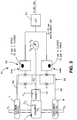
- the compressor 1 basically includes a cylinder or casing 3, a compression chamber C C defined within the casing 3, and a compression member or piston 4 movably disposed within the chamber C C
- the unloader 2 includes a housing 5 defining a fixed volume chamber C U .
- the valve assembly 10 comprises a base 14 disposed generally between the compression and unloader chambers C C , C U , at least one and preferably a plurality of passages 16 extending through the base 14 and fluidly connecting the two chambers C C , C U , and at least one and preferably a plurality of valve seats 18 each defined about a section of a separate one of the passages 16.
- At least one and preferably a plurality of stem bores 20 are each defined within the base 14 so as located at least generally proximal to a separate valve seat 18.
- Each stem bore 20 has a control chamber section 22, a central axis 20a, and an inner circumferential surface 21 extending about the axis 20a.
- the one or more valve closing elements 12 each basically comprises a generally cylindrical main body 24 movably disposed at least partially within a separate one of the stem bores 20, so as to be displaceable generally along the bore axis 20a, and at least one sealing member 26 coupled with and disposed generally about the main body 24.
- Each cylindrical main body 24 has a sealing end surface 28 disposeable against the proximal valve seat 18 so as to substantially obstruct the valve passage 16, thereby preventing fluid flow therethrough, and an opposing control end surface 30 disposed within the stem bore control chamber section 22.
- the closing element main body 24 is displaceable with respect to the associated stem bore 20 (i.e., along the bore axis 20a) between a closed position p C ( Figs. 4 and 10 ), at which the main body sealing surface 28 is disposed generally against the proximal valve seat 18, and at least one and preferably a plurality of open positions p O ( Fig. 5 ) spaced axially from the closed position p C , at which the main body sealing surface 28 is spaced from the associated valve seat 18. That is, the one or more valve open positions p O are each any position of the main body 24 along the axis 20a at which the sealing end surface 28 is spaced from the associated valve seat 18.
- each closing element main body 24 (and thus also the coupled sealing member 26) is biased and/or displaced generally toward the closed position p C ( Figs.
- each sealing member 26 of each closing element 12 is configured to substantially prevent fluid flow between the control chamber section 22 and the valve fluid passage 16 through the associated stem bore 20, i.e., through any space between the main body 24 and the stem bore 20.
- each sealing member 26 has an outer circumferential sealing surface 27 disposeable against or engageable with the stem bore 20 so as to prevent fluid flow between the stem bore chamber section 22 and the associated valve passage 16.
- the sealing member(s) 26 are each configured such that at least a portion of the outer circumferential sealing surface 27 remains disposed against/engaged with the stem bore 20 as the main body 24 displaces between the closed and open positions p C , p O .
- each closing element 12 includes a single sealing member 26 (e.g., formed as a tube, sleeve, ring, etc.) having an axial length L S ( Fig. 7 ) sufficiently greater than the total axial displacement d A ( Fig. 5 ) of the main body member 24, thus enabling at least a portion of the sealing surface 27 to always remains in contact with and/or engaged with the stem bore 20.
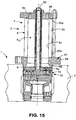
- each closing element 12 may alternatively include two or more members 26 (e.g., generally annular rings) spaced axially upon the main body 24 and arranged such that at least one member 26 is always engaged with the stem bore 20, as shown in Fig. 16 and discussed in greater detail below.
- the sealing member 26 and/or the cylindrical main body 24 of each closing element 12 are/is further configured to enable radial movement or displacement of the main body 24 with respect the bore axis 20a, such that the main body sealing surface 28 is at least generally alignable with the valve seat 18.
- the structure of the sealing member 26 and/or the main body 24, and the manner by which the two components 24, 26 are connected together permits the main body 24 to move or shift radially or transversely, during axial displacement of the body 24 toward the valve seat 18, as necessary to enable the closing element main body 24 to properly mate with the valve seat 18.
- each valve seat 18 is generally centered about an axis 18a and the sealing surface 28 of each main body 24 is generally centered about an axis 24a through the main body 24, as discussed below.
- the main body 24 and/or the sealing member 26 of each element 12 is configured to enable sufficient radial displacement d R of the main body 24 with respect to the bore axis 20a such that when the sealing surface axis 24a is spaced radially apart from the valve seat axis 18a (see Fig. 9 ), the sealing surface axis 24a becomes generally coaxially aligned with the valve seat axis 18a when the body sealing surface 28 contacts the valve seat 18, as shown in Fig. 10 .
- each closing element 12 is displaceable in first and second, opposing directions D 1 , D 2 along the stem bore axis 20a generally toward the associated valve seat 18.
- the main body 24 and/or the sealing member 26 are/is configured such that when the sealing surface 28 is misaligned with the valve seat 18 (i.e., axes 24a, 18a being spaced radially apart), contact between a radially-outermost portion 28a ( Figs.
- the capability of radially moving/displacing the closing element main body 24 with respect to the bore axis 20a is provided by forming or sizing both the main body 24 and the sealing member 26 so as to form generally annular clearance spaces S CI , S CO1 , S CO2 between the sealing member 26, the main body 24, and stem bore 20, as described in detail below.
- the closing element main body 24 has a longitudinal axis 24a and an outer circumferential surface 32 extending about the axis 24a, the surface 32 having an outside diameter OD M1 .
- the sealing member 26 has an inner circumferential surface 34 with an inside diameter ID S
- the opposing outer circumferential sealing surface 27 (discussed above) has an outside diameter OD S .
- the sealing member inner surface 34 is disposed generally coaxially about the main body outer surface 32 and, as discussed above, the sealing outer surface 27 is disposeable against the stem bore inner circumferential surface 21 to substantially prevent gas flow between the main body sealing and control ends 28, 30.
- the inside diameter ID S of the sealing member inner surface 34 is sufficiently larger or greater than the outside diameter OD M of the main body outer surface 32 such that a generally annular, inner clearance space S CI is defined between the sealing member 26 and the closing element main body 24.
- the inner clearance space S CI enables the main body 24 to be moveable radially with respect to (i.e., and within) the sealing member 26.
- the main body 24 preferably has at least one and most preferably two second, radially-larger outer circumferential surfaces 38A, 38B each having an outside diameter OD M2 greater than the diameter OD M1 "first" or radially-smaller outer surface 32, and preferably larger than the sealing member inner surface inside diameter ID S , for reasons described below.
- the outside diameter OD S of the sealing member outer surface 27 i.e., which is engaged with the bore surface 21
- these outer clearance spaces S CO1 , S CO2 enable the main body 24 to be moveable radially with respect to (and within) the stem bore 20.
- the capability of radially moving/displacing the closing element main body 24 with respect to the bore axis 20a is preferably provided by forming or sizing both the main body 24 and the sealing member 26 so as to define the generally annular clearance spaces S CI , S CO1 , S CO2 between the sealing member 26, the main body 24, and stem bore 20.
- the main body 24 and/or the sealing member 24 may be configured or constructed in any other appropriate manner that enables or permits radial movement of the main body 24 within the bore 20.
- the sealing member 26 may be coupled to the main body 24 without any substantial clearance and be formed so as to be radially deflectable or compressible, or formed/provided with a radially deflectable/moveable portion.
- the main body 24 is radially displaceable with respect to the bore axis 20a by deflection, compression, or displacement of the sealing member 26.
- the scope of the present invention encompasses these and all other structures of the main body 24 and sealing member 26 that enable radial movement and other functioning of the valve closing element 12 as generally described herein.
- valve seat 18 preferably includes a beveled or generally frustaconical inner surface 19 ( Fig. 5 ) extending circumferentially about a section of the valve passage 16 and the main body sealing surface 28 has a mating beveled or generally frustaconical outer surface section 29.
- the main body frustaconical surface section 29 is sized to fit against the valve seat frustaconical surface 19 so as to substantially obstruct or seal the valve passage 16.
- contact between the mating surfaces 29, 19 substantially seals an opening or inlet port 16a of the valve passage 16, which is surrounded by the valve seat surface 19, so as to at least substantially prevent fluid flow through the port 16a.
- the capability of radially moving the main body 24 with respect to both the sealing member 26 and the stem bore 20 enables the main body outer frustaconical surface section 29 to align with the valve seat inner frustoconical surface 19 as the closing element body 24 displaces generally toward the valve seat 18, as best shown in Figs. 9-12 , while the sealing member 26 still prevents fluid flow between the control chamber section 22 and valve passage 16 through the stem bore 20.
- the two radially-larger outer surfaces 38A, 38B are spaced axially apart and are each located generally proximal to a separate body end surface 28, 30, respectively, and the radially smaller outer surface 32 is disposed generally axially between the two larger outer surfaces 38A, 38B.
- a generally annular recess 42 is defined generally between the radially larger outer surfaces 38A, 38B, which is configured to receive a portion of the sealing member 26 so as to couple the sealing member 26 to the main body 24.
- the sealing member 26 has opposing axial ends 26a, 26b and an axial length L S that is preferably slightly lesser (or even substantially equal or slightly greater) than the axial length L MI of the main body radially-smaller outer surface 32 (see Fig. 7 ).
- the main body 24 also has generally facing radial shoulders 44 extending generally radially between each axial end 32a, 32b of the radially smaller outer surface and the proximal radially-larger outer surface 38A, 38B.
- the sealing member 26 is sized to be partially disposed within the main body recess 42 and is axially retained therein by the radial shoulders 44, thereby coupling or connecting the sealing member 26 with the main body 24 so as to seal the inner clearance space S CI from the outer clearance spaces SCO1, S CO2 .
- the valve assembly 10 is constructed such that the main body 24 of each closing element 12 is displaceable within the associated stem bore 20 when pressure P S , P C on one of the two main body end surfaces 28, 30, respectively, is sufficiently greater than pressure P C , P S on the other one of the two main body end surfaces 30, 28. That is, the cylindrical main body 24 displaces in the first direction D 1 along the stem axis 20a and toward the valve seat 18 when the main body 24 is spaced from the valve seat 18 and pressure P C on the control end surface 30 is sufficiently greater than pressure P S on the sealing end surface 28.
- the cylindrical main body 24 displaces in a second direction D 2 along the stem axis 20a and generally away from the valve seat 18 when the main body 24 is at least generally proximal to the valve seat 18 and pressure P S on the sealing end surface 28 is sufficiently greater than pressure P C on the control end surface 30.
- the compressor 1 preferably further has an inlet 7 and an outlet 8 (see Fig. 10 ) each fluidly coupled with the compression chamber C C
- the valve assembly 10 further includes a control fluid line 50 fluidly connected with the control chamber section 22 of each stem bore 20 and with the compressor inlet 7 or/and the compressor outlet 8.
- the closing element main body 24 is displaced generally toward and/or disposed against the valve seat 18 when pressure P I , P O at the inlet 7 or/and at the outlet 8 is greater than pressure P C in the compression chamber C C .
- the main body member 24 is displaced generally away from or/and held spaced from the valve seat 18 when pressure P I , P O at the inlet 7 or/and at the outlet 8 is lesser than pressure P C in the compression chamber C C .
- the pressure P S on the main body sealing end surface 28 is generally equal to pressure P C in the compression chamber C C and pressure on the main body control surface 30 is either generally equal to the pressure P I or P O at a connected one of the inlet 7 or outlet 8, a portion of one such pressure P I , P O , or a combination of the inlet and outlet pressures P I , P O or portions thereof.
- the valve assembly 10 preferably further has a control fluid assembly 54 including the control line 50 and a pressure regulator 56, and the control fluid line 50 preferably includes three separate fluid line sections 58, 60, 62 coupled with the regulator 56.
- the control fluid line 50 preferably includes three separate fluid line sections 58, 60, 62 coupled with the regulator 56.
- an inlet line section 58 is fluidly connected with the compressor inlet 7 and the regulator 56 and an outlet line section 60 is fluidly connected with the compressor outlet 8 and the regulator 56.
- a control output line section 62 extends between at least one and preferably all of stem bore control chambers 22 and the pressure regulator 56.
- the regulator 56 is configured to adjust pressure in the output line section 64 between pressure P I at the compressor inlet 7 and at the compressor outlet 8.
- the regulator 56 preferably includes a first valve 64A configured to control flow through the inlet fluid line 58, a second valve 64B configured to flow through outlet fluid line 60, and a controller 63 configured to operate the two valves 64A, 64B so as to provide a desired ratio of the inlet and outlet pressures P I , P O .
- the two valves 64A, 64B may be manually operable, such as by means of a handle, etc.
- the valve assembly 10 of the present invention functions generally as follows.
- the pressure within the chamber section c V1 , c V2 (discussed below) to which the unloader chamber is fluidly connectable (i.e., through the valve 10) begins to increase.
- the pressure P C in the compressor chamber section C C increases to the point that the pressure P S on the valve sealing end surface 28 of each closing element 12 is greater than the pressure on the pressure P C on the associated control end surface 30.
- the one or more valve closing elements 12 are displaced toward an open position p O , thereby fluidly coupling the compressor chamber section c V1 or c V2 with the unloader chamber C U .
- Process fluid flows into the unloader chamber C U through the valve passage(s) 16 until the pressure P S at the closing element sealing surface 28 becomes lesser than the control chamber pressure P C acting on the control end surface 30, at which point the net pressure acting on each closing element main body 24 causes the main body 24 to displace to the closed position p C .
- the unloader chamber C U is again isolated or sealed from the compressor chamber C C .
- each closing element 12 By having the improved closing element(s) 12 of the present invention, leakage of control fluid about each closing element 12 is at least reduced, and preferably substantially prevented.
- the closing elements 12 are operable with a lesser required control pressure P C acting on the main body 24, as fluid leakage would require a greater control gas pressure P C to accommodate for the fluid loss due to leakage.
- the closing elements 12 and the required tubing or other components to establish the control fluid line 50 may be used for a greater range of operating conditions and with a variety of different sized compressors 1.
- a fluid e.g., nitrogen
- the process fluid e.g., natural gas
- a completely separate control fluid assembly 54 with a source of control gas may be constructed and used to control the unloader valve assembly 10.
- valve assembly 10 and the valve closing element 12 of the present invention are described in greater detail below.
- the valve assembly 10 is preferably used with a compressor 1 having a casing 3 with at least one and preferably a plurality of unloader holes 9 extending into, or at least fluidly coupled with, the compression chamber C C .
- Each unloader hole 9 is preferably configured to receive at least a portion of a separate unloader valve base 14, as described above and in further detail below, such that the valve passage(s) 14 control flow between the compression chamber C C and the associated unloader chamber C U .
- the compressor 1 may be provided with only a single unloader 2 or two or more unloaders 2, as necessary to achieve the desired operating characteristics for a particular compressor 1.
- each unloader hole 9 is located such that a variable volume chamber section c V1 or c V2 of the compressor chamber C C , i.e., each located on an opposing side of the piston 4, is fluidly coupled with each unloader 2 through the one or more passages 16 of the unloader valve assembly 10.
- the preferred compressor 1 is configured or constructed such that movement of the compression member or piston 4 varies the volume and pressure within each compressor chamber section c V1 or c V2 .
- the control fluid line 50 is configured to fluidly connect the one or more stem bore control chambers 22 with the compressor inlet 7 and/or outlet 8 such that pressure variation within the compressor chamber variable section c V1 , c V2 adjusts or varies the pressure P S on both the closing element sealing end surface(s) 28 and the pressure P C on the control end surface(s) 30.
- pressure variations displace each closing element 12 between the closed and open positions p C , p O , as discussed above.
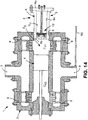
- the housing 5 of each unloader 2 preferably includes a generally tubular body 6 adapted to receive or connect with one valve base 14 and either directly mountable to the compressor 1, or/and connected therewith by means of the valve base 14.
- the unloader body 6 has an enclosed end 6a, an opposing open end 6b, and a central bore 6c extending between the two ends 6a, 6b and providing the unloader chamber C U .
- the unloader body 6 includes a generally circular tubular sidewall 65 having opposing ends 65a, 65b, a generally circular end plate 66 attached to the sidewall outer end 65a and a generally annular mounting plate 67 attached to the sidewall inner end 65b.
- the mounting plate 67 provides a mounting flange 68 connectable with the compressor casing 3 and includes a circular engagement wall 69 disposeable within a casing unloader hole 9.
- each valve 10 is sized to fit at least partially within one casing hole 9 so as to generally restrict flow through the hole 9, so that the compression and unloader chambers C C , C U are fluidly connected through the one or more valve passages 16.
- Each valve base 14 is disposed against, or within, the unloader body open end 6b, most preferably against the unloader engagement wall 69, so as to generally enclose the unloader chamber C U .
- the valve base 14 includes a generally cylindrical body 80 having first and second ends 80a, 80b and a central axis 81 extending between the two ends 80a, 80b.
- a plurality of first valve passage holes 82 extend into the body 80 from the first end 80a and partially therethrough generally toward the body second end 80b and a plurality of second valve passage holes 84 extending into the body from the second end 80b and partially therethrough generally axially toward the body first end 80a.
- At least one connective passage 86 extends generally radially within the body 80 and fluidly connects at least one of the first valve holes 82 with at least one second valve hole 84 so as to form at least one valve passage 16.
- cylindrical valve base body 80 also includes a plurality of bore holes 88 axially aligned with a separate one of the second valve passage holes 84 and having a first end 88a fluidly connected with at least one connective passage 86 and an opposing second end 88a.
- Each body bore hole 88 provides a separate one of the stem bores 20 and as such, are sized to receive a separate one of the closing elements 12 such that a control chamber section 22 is defined between the closing element main body 24 and the body bore hole second end 88b.
- a plurality of control ports 90 extending generally into the control chamber section 22 of a separate one of the stem bore holes 88 and a central control fluid hole 92 extends into the valve body 80 from the first end 80a and partially therethrough generally toward the body second end 80b, the control hole 92 being connectable with a source of control pressure, as discussed above.
- At least one control connective passage 94 extends generally radially within the valve body 80 and fluidly connects the control hole 92 with one or more of the control ports 90, thereby fluidly connecting the control pressure source, i.e., the inlet 7 and/or outlet 8 or separate source (none shown), with each of the stem bore control chamber sections 20.
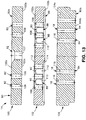
- the above-discussed cylindrical valve base body 80 is formed of an assembly of three connected-together, generally circular plates 100, 102, 104.
- a first or outer plate 100 has an outer axial end 100a providing the valve body first end 80a, an opposing inner axial end 100b, a plurality of through holes 106 each providing an outer section of a separate one of the first valve passage holes 82, and a central through bore providing the control fluid hole 92.
- a second or middle plate 102 has first and second opposing axial ends 102a, 102b, the middle plate first end 102a being disposed against the outer plate inner end 100a, a plurality of through holes 108 each providing an inner section of a separate one of the first valve passage holes 82 and a plurality of counterbore holes 110 each providing a separate one of the stem bore holes 20 and the connected control ports 90.
- a plurality of radially-extending recesses 112 each extend into the second plate 102 from the plate first end 102a and are each connected with at least one control port 90 and provide one control connective passage 94.
- a generally annular recess 114 extends into the middle plate 102 from the plate second end 102b and provides a common connective passage 86 for all the valve passages 14.
- a third or inner plate 104 has an outer axial end 104b providing the valve body second end 80b, an opposing inner axial end 104a disposed against the middle plate second end 102b and a plurality of through holes 116 each providing a separate one of the second valve passage holes 84.
- each closing element main body 24 is preferably formed as a generally circular cylindrical body 120 having a central circumferential cut-out 122 providing the annular recess 42, as described above, and defining upper and lower, generally circular head portions 124A, 124B.
- Each generally circular head portion 124A, 124B provides a separate one of the radially-larger outer surface sections 38A, 38B described above.
- the cylindrical body 120 is solid and formed as a one piece construction, but may be formed of multiple connected pieces and/or may have a generally hollow interior.
- the cylindrical main body 24 may have any other appropriate shape, such as a generally ovular, generally hexagonal, and/or may have any appropriate structure for retaining the sealing member 26, such that the closing element 12 is capable of generally functioning as descried herein.
- each valve closing element 12 preferably includes a single sealing member 26 including a generally circular tubular sleeve 130 having inner and outer circumferential surfaces 132, 134.
- the tubular sleeve 130 is engage with the main body 24, specifically with the annular recess 42, so as to form an inner annular clearance space S CI , as described above.
- each valve closing element 12 may alternatively include two or more axially spaced sealing members 26, each formed for example, as a tubular sleeve 130 (as shown in Fig. 16 ), an annular ring, etc. In another alternative construction shown in Figs.
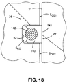
- each sealing member 26 may be formed so as to include an outer sealing ring 140 disposed at least partially within the main body annular recess 42, the outer ring having an outer circumferential surface 141 disposeable against the stem bore 20, and an inner support ring 142.
- the support ring 142 is disposed within the recess 42 and is configured to generally prevent deflection of the outer sealing ring 140 generally radially toward the main body axis 24a.
- the sealing member 26 (or/and the main body 24) may alternatively be formed with one or more flexible centering members (e.g., cantilever arms, etc.) extending between the sealing member inner surface 34 and the main body outer surface 32 and permitting relative radial displacement of the main body 24 (structure not shown).
- main closing element main body 24 is preferably formed of a metallic material (e.g., alloy steel) and the at least one sealing member 26 is preferably formed of a polymeric material, most preferably polytetrafluroethylene (“PTFE”), although either component 24 or 26 may be formed of any appropriate material as desired.
- PTFE polytetrafluroethylene
Landscapes
- Engineering & Computer Science (AREA)
- Mechanical Engineering (AREA)
- General Engineering & Computer Science (AREA)
- Compressor (AREA)
- Lift Valve (AREA)
Claims (14)
- Schließelement einer Ventilanordnung (10) eines Kompressorentladers eines Kompressors, wobei der Kompressor ein Gehäuse (3) und eine Kompressionskammer (Cc) aufweist, die innerhalb des Gehäuses (3) definiert ist, und wobei der Kompressorentlader ein Gehäuse (5) aufweist, das eine Entladerkammer (Cu) mit festem Volumen definiert, und wobei die Ventilanordnung (10) eine Basis (14), die zwischen den Kompressions- und Entladekammern angeordnet ist, einen Durchgang, der sich durch die Basis (14) erstreckt und die Kompressions- und Entladekammern (Cc, Cu) fluidmäßig verbindet, einen Sitz (18), der um einen Abschnitt des Durchgangs definiert ist, und eine Schaftbohrung (20) aufweist, die innerhalb der Basis (14) definiert ist und einen Bohrungssteuerkammerabschnitt (22) und eine zentrale Achse aufweist, wobei das Ventilanordnungsschließelement umfasst:einen zylindrischen Hauptkörper (24), der bewegbar wenigstens teilweise innerhalb der Schaftbohrung (20) angeordnet ist, um so entlang einer Bohrungsachse (20a) verschiebbar zu sein, wobei der zylindrische Hauptkörper (24) eine abdichtende Endfläche (28), wobei die abdichtende Endfläche (28) gegen eine Ventilsitzfläche anordenbar ist, um so einen Ventildurchgang (16) zu blockieren, und eine gegenüberliegende Steuerendfläche (30) aufweist, die in dem Bohrungssteuerkammerabschnitt (22) angeordnet ist; und gekennzeichnet durchein Dichtungselement (26), das um den zylindrischen Hauptkörper (24) angeordnet und zwischen den Dichtungs- und Steuerendflächen (28, 30) verortet ist, wobei das Dichtungselement (26) konfiguriert ist, um einen Fluidfluss zwischen dem Bohrungssteuerkammerabschnitt (22) und dem Ventilkanal (16) durch die Schaftbohrung (20) zu verhindern, wobei wenigstens einer vom zylindrischen Hauptkörper (24) und vom Dichtungselement (26) so konfiguriert ist, dass der zylindrische Hauptkörper (24) radial beweglich in Bezug auf die Bohrungsachse (20a) ist, um die zylindrische Hauptkörperdichtungsendfläche (28) mit dem Ventilsitz (18) auszurichten,wobei das Dichtungselement (26) einen ringförmigen Körper, der teilweise innerhalb einer zylindrischen Hauptkörperausnehmung (42) angeordnet ist, und eine äußere Umfangsfläche (27) aufweist, die gegen die Schaftbohrung (20) anordenbar ist.
- Ventilschließelement nach Anspruch 1, wobei der Ventilsitz (18) um eine Achse zentriert ist, wobei die Dichtungsfläche des zylindrischen Hauptkörpers (24) um eine Achse durch den zylindrischen Hauptkörper zentriert ist und der/das wenigstens eine von zylindrischem Hauptkörper und von Dichtungselement (26) so konfiguriert ist, um eine ausreichende radiale Verschiebung des zylindrischen Hauptkörpers in Bezug auf die Bohrungsachse (20a) zu ermöglichen, so dass, wenn die Dichtungsflächenachse radial von der Ventilsitzachse beabstandet ist, die Dichtungsflächenachse koaxial zur Ventilsitzachse ausgerichtet wird, wenn die Körperdichtungsfläche mit dem Ventilsitz (18) in Kontakt kommt.
- Ventilschließelement nach Anspruch 1, wobei der zylindrische Hauptkörper (24) in einer ersten Richtung entlang der Schaftbohrungsachse in Richtung des Ventilsitzes (18) verschiebbar ist, wobei der/das wenigstens eine von zylindrischem Hauptkörper und Dichtungselement (26) so konfiguriert ist, dass wenn die Dichtungsfläche mit dem Ventilsitz (18) nicht ausgerichtet ist, der Kontakt zwischen einem radial äußersten Abschnitt der Dichtungsfläche und dem Ventilsitz (18), während der zylindrische Hauptkörper sich in die erste Richtung verschiebt, den zylindrischen Hauptkörper radial so weit schiebt, bis die Dichtungsfläche gegen den Ventilsitz (18) zentriert ist.
- Ventilschließelement nach Anspruch 1, wobei:der Ventilsitz (18) eine kegelstumpfförmige Innenfläche aufweist, die sich in Umfangsrichtung um einen Abschnitt des Ventildurchgangs (16) erstreckt;die Dichtungsfläche des zylindrischen Hauptkörpers einen kegelstumpfförmigen Außenflächenabschnitt aufweist, der so dimensioniert ist, dass er gegen die konische Fläche des Sitzes (18) verschiebbar ist, um so den Ventildurchgang (16) abzudichten; undder/das wenigstens eine von zylindrischem Hauptkörper und von Dichtungselement (26) konfiguriert ist, um eine radiale Verschiebung des zylindrischen Hauptkörpers in Bezug auf die Achse der Schaftbohrung (20) zu ermöglichen, um den äußeren kegelstumpfförmigen Flächenabschnitt des zylindrischen Hauptkörpers in Bezug auf die innere kegelstumpfförmige Fläche des Ventilsitzes (18) auszurichten, wenn der zylindrische Hauptkörper (24) zum Ventilsitz (18) hin verschoben wird.
- Ventilschließelement nach Anspruch 1, wobei:der zylindrische Hauptkörper (24) eine Längsachse und eine Außenumfangsfläche, die sich um die Achse erstreckt, aufweist, wobei die Außenfläche einen Außendurchmesser hat; unddas Dichtungselement (26) eine innere Umfangsfläche aufweist, die sich um die zylindrische Hauptkörperaußenfläche erstreckt und einen Innendurchmesser aufweist, wobei der Innendurchmesser des Dichtungselements (26) größer ist als der Außendurchmesser der zylindrischen Hauptkörperfläche, so dass ein ringförmiger, innerer Zwischenraum zwischen dem Dichtungselement (26) und dem zylindrischen Hauptkörper definiert ist, so dass der zylindrische Hauptkörper in Bezug auf das Dichtungselement (26) radial bewegbar ist.
- Ventilschließelement nach Anspruch 1, wobei:der zylindrische Hauptkörper (24) eine zentrale Längsachse, die sich zwischen den Dichtungs- und Steuerflächen erstreckt, eine äußere Umfangsfläche, die sich um die Körperachse erstreckt, und eine ringförmige Vertiefung aufweist, die sich von der äußeren Fläche radial nach innen erstreckt; unddas Dichtungselement (26) den ringförmigen Körper umfasst, der teilweise innerhalb der zylindrischen Hauptkörperaussparung (42) angeordnet ist, um so den ringförmigen Körper mit dem zylindrischen Hauptkörper zu verbinden, wobei der ringförmige Körper eine innere Umfangsfläche, die so bemessen ist, dass sie einen inneren Freiraum zwischen dem ringförmigen Körper und der zylindrischen Hauptkörperausnehmung (42) definiert, um eine radiale Bewegung des zylindrischen Hauptkörpers in Bezug auf das Dichtungselement (26) zu ermöglichen, und die äußere Umfangsfläche aufweist, die in Bezug auf die zylindrische Hauptkörperaußenfläche radial nach außen beabstandet ist, so dass ein äußerer Freiraum zwischen der äußeren Fläche des zylindrischen Hauptkörpers und der Schaftbohrung (20) definiert ist, wobei der äußere Freiraum eine radiale Bewegung des zylindrischen Hauptkörpers in Bezug auf die Schaftbohrung (20) zulässt.
- Ventilschließelement nach Anspruch 1, wobei der zylindrische Hauptkörper (24) innerhalb der Schaftbohrung (20) entlang der Achse der Schaftbohrung (20) verschiebbar ist, wenn der Druck auf eine von Dichtungsendfläche (28) und Steuerendfläche (30) größer ist als der Druck auf die andere von Dichtungsendfläche (28) und Steuerendfläche (30).
- Ventilschließelement nach Anspruch 1, wobei
der Kompressor ferner einen Einlass und einen Auslass aufweist, die jeweils fluidisch mit der Kompressionskammer (Cc) verbunden sind; und
die Ventilanordnung (10) ferner eine Steuerfluidleitung aufweist, die fluidisch mit dem Steuerkammerabschnitt (22) der Schaftbohrung (20) und wenigstens einem von Kompressoreinlass und Kompressorauslass verbunden ist, so dass der zylindrische Hauptkörper zu diesem hin verschoben wird und an dem Ventilsitz (18) angeordnet wird, wenn der Druck an wenigstens einem von Einlass und/oder Auslass größer ist als der Druck in der Kompressionskammer (Cc), und das zylindrische Hauptkörperelement von dem Ventil weg verschoben und vom Ventilsitz (18) beabstandet wird, wenn der Druck am Einlass und/oder Auslass geringer ist als der Druck in der Kompressionskammer (Cc). - Ventilschließelement nach Anspruch 1, wobei:der Kompressor ferner einen Einlass und einen Auslass umfasst, die jeweils fluidisch mit der Kompressionskammer (Cc) verbunden sind, und die Ventilanordnung (10) ferner eine Steuerfluidleitung umfasst, die fluidisch mit dem Steuerkammerabschnitt (22) der Schaftbohrung (20) und wenigstens einem von Kompressoreinlass und Kompressorauslass verbunden ist;der zylindrische Hauptkörper (24) sich zum Ventilsitz (18) hin verschiebt und an diesem angeordnet ist, wenn der Druck an dem wenigstens einen fluidisch verbundenen Einlass und Auslass größer ist als der Druck in der Kompressionskammer (Cc); undder zylindrische Hauptkörper sich vom Ventilsitz (18) weg verschiebt und von ihm beabstandet ist, wenn der Druck am Einlass und/oder Auslass geringer ist als der Druck in der Kompressionskammer (Cc).
- Ventilschließkörper nach Anspruch 1, wobei der zylindrische Hauptkörper zwischen einer ersten Position, an der die Körperdichtungsfläche gegen den Ventilsitz (18) angeordnet ist, und einer zweiten Position, an der die Körperdichtungsfläche vom Ventilsitz (18) beabstandet ist, derart verschiebbar ist, dass der Ventildurchgang (16) die Kompressionskammer (Cc) fluidmäßig mit der Entladerkammer verbindet.
- Ventilverschlusselement nach Anspruch 1, wobei:der zylindrische Hauptkörper (24) in Bezug auf die Schaftbohrung verschiebbar (20) zwischen einer geschlossenen Position, an der die zylindrische Hauptkörperdichtungsfläche am Ventilsitz (18) angeordnet ist, und wenigstens einer offenen Position, an der die zylindrische Hauptkörperdichtungsfläche vom Ventilsitz (18) beabstandet ist, verschiebbar ist; undder zylindrische Hauptkörper (24) in Richtung auf die geschlossene Position vorgespannt ist, wenn der Druck auf die Steuerfläche größer ist als der Druck auf die Dichtungsfläche, und der Hauptkörper alternativ zur wenigstens einen offenen Position vorgespannt ist, wenn der Druck auf die Dichtungsfläche größer ist als der Druck auf die Steuerfläche.
- Ventilschließelement nach Anspruch 1, wobei:die Ventilbasis (14) eine innere Umfangsfläche aufweist, die sich um die Bohrungsachse (20a) erstreckt und wenigstens teilweise die Schaftbohrung (20) definiert;der zylindrische Hauptkörper entlang der Bohrungsachse (20a) aus einer geschlossenen Position, in der die Dichtungsfläche gegen den Ventilsitz (18) angeordnet ist, und einer offenen Position verschiebbar ist, in der die Dichtungsfläche vom Ventilsitz (18) beabstandet ist, so dass die Kompressorkammer (Cc) mit der Entladerkammer in Fluidverbindung steht; undwenigstens ein Abschnitt des wenigstens einen Dichtungselements (26) in Kontakt mit der Innenfläche der Schaftbohrung (20) bleibt, wenn der zylindrische Hauptkörper zwischen der geschlossenen und der offenen Position verschoben wird.
- Ventilschließelement nach Anspruch 1, wobei das Dichtungselement (26) ferner eine innere Umfangsoberfläche aufweist, wobei die innere Umfangsoberfläche um einen Abschnitt des zylindrischen Hauptkörpers (24) herum angeordnet werden kann.
- Ventilschließelement nach Anspruch 1, wobei das Dichtungselement (26) wenigstens zwei axial beabstandete ringförmige Körper aufweist, die jeweils innere und äußere Umfangsflächen aufweisen, wobei die Innenfläche jedes ringförmigen Elements um einen Abschnitt des ringförmigen Elements des zylindrischen Hauptkörpers (24) herum angeordnet werden kann und die Außenfläche jedes ringförmigen Elements sind gegen wenigstens einen Abschnitt der Schaftbohrung (20) angeordnet werden kann, um eine Dichtung zu bilden.
Applications Claiming Priority (2)
| Application Number | Priority Date | Filing Date | Title |
|---|---|---|---|
| US78795206P | 2006-03-31 | 2006-03-31 | |
| PCT/US2007/008149 WO2007120506A2 (en) | 2006-03-31 | 2007-04-02 | Control valve assembly for a compressor unloader |
Publications (3)
| Publication Number | Publication Date |
|---|---|
| EP2013479A2 EP2013479A2 (de) | 2009-01-14 |
| EP2013479A4 EP2013479A4 (de) | 2015-10-14 |
| EP2013479B1 true EP2013479B1 (de) | 2018-11-21 |
Family
ID=38610056
Family Applications (1)
| Application Number | Title | Priority Date | Filing Date |
|---|---|---|---|
| EP07754641.4A Active EP2013479B1 (de) | 2006-03-31 | 2007-04-02 | Steuerventilanordnung für einen kompressorenentlader |
Country Status (6)
| Country | Link |
|---|---|
| US (1) | US8070461B2 (de) |
| EP (1) | EP2013479B1 (de) |
| BR (1) | BRPI0710100B1 (de) |
| CA (1) | CA2647511C (de) |
| MX (1) | MX2008012579A (de) |
| WO (1) | WO2007120506A2 (de) |
Families Citing this family (37)
| Publication number | Priority date | Publication date | Assignee | Title |
|---|---|---|---|---|
| US8075668B2 (en) | 2005-03-29 | 2011-12-13 | Dresser-Rand Company | Drainage system for compressor separators |
| EP2063978B1 (de) | 2006-09-19 | 2014-07-09 | Dresser-Rand Company | Dichtung für drehabscheidertrommel |
| CA2663531C (en) | 2006-09-21 | 2014-05-20 | William C. Maier | Separator drum and compressor impeller assembly |
| MX2009003175A (es) | 2006-09-25 | 2009-04-03 | Dresser Rand Co | Cubierta de acceso para bobina conectora presurizada. |
| CA2663883C (en) | 2006-09-25 | 2015-02-03 | Kevin M. Majot | Coupling guard system |
| WO2008039733A2 (en) | 2006-09-25 | 2008-04-03 | Dresser-Rand Company | Compressor mounting system |
| WO2008039446A2 (en) | 2006-09-25 | 2008-04-03 | Dresser-Rand Company | Fluid deflector for fluid separator devices |
| BRPI0717087B1 (pt) | 2006-09-25 | 2018-10-16 | Dresser Rand Co | sistema de carretel conector para conectar um primeiro componente e um segundo componente de um sistema de compressão industrial |
| EP2415507A1 (de) | 2006-09-26 | 2012-02-08 | Dresser-Rand Company | Verbesserte statische Flüssigkeitstrennungsvorrichtung |
| WO2009111616A2 (en) | 2008-03-05 | 2009-09-11 | Dresser-Rand Company | Compressor assembly including separator and ejector pump |
| US8062400B2 (en) | 2008-06-25 | 2011-11-22 | Dresser-Rand Company | Dual body drum for rotary separators |
| US8079805B2 (en) | 2008-06-25 | 2011-12-20 | Dresser-Rand Company | Rotary separator and shaft coupler for compressors |
| US7922218B2 (en) | 2008-06-25 | 2011-04-12 | Dresser-Rand Company | Shear ring casing coupler device |
| US8087901B2 (en) | 2009-03-20 | 2012-01-03 | Dresser-Rand Company | Fluid channeling device for back-to-back compressors |
| US8210804B2 (en) | 2009-03-20 | 2012-07-03 | Dresser-Rand Company | Slidable cover for casing access port |
| US8061972B2 (en) | 2009-03-24 | 2011-11-22 | Dresser-Rand Company | High pressure casing access cover |
| US8414692B2 (en) | 2009-09-15 | 2013-04-09 | Dresser-Rand Company | Density-based compact separator |
| US9095856B2 (en) | 2010-02-10 | 2015-08-04 | Dresser-Rand Company | Separator fluid collector and method |
| US8663483B2 (en) | 2010-07-15 | 2014-03-04 | Dresser-Rand Company | Radial vane pack for rotary separators |
| WO2012009158A2 (en) | 2010-07-15 | 2012-01-19 | Dresser-Rand Company | Enhanced in-line rotary separator |
| US8657935B2 (en) | 2010-07-20 | 2014-02-25 | Dresser-Rand Company | Combination of expansion and cooling to enhance separation |
| US8821362B2 (en) | 2010-07-21 | 2014-09-02 | Dresser-Rand Company | Multiple modular in-line rotary separator bundle |
| JP5936144B2 (ja) | 2010-09-09 | 2016-06-15 | ドレッサー ランド カンパニーDresser−Rand Company | 洗浄可能に制御された排水管 |
| US8994237B2 (en) | 2010-12-30 | 2015-03-31 | Dresser-Rand Company | Method for on-line detection of liquid and potential for the occurrence of resistance to ground faults in active magnetic bearing systems |
| EP2659277B8 (de) | 2010-12-30 | 2018-05-23 | Dresser-Rand Company | Verfahren zur online-erkennung von bodenwiderstandsfehlern in aktiven magnetlagersystemen |
| US9551349B2 (en) | 2011-04-08 | 2017-01-24 | Dresser-Rand Company | Circulating dielectric oil cooling system for canned bearings and canned electronics |
| US8876389B2 (en) | 2011-05-27 | 2014-11-04 | Dresser-Rand Company | Segmented coast-down bearing for magnetic bearing systems |
| US8851756B2 (en) | 2011-06-29 | 2014-10-07 | Dresser-Rand Company | Whirl inhibiting coast-down bearing for magnetic bearing systems |
| JP2016150130A (ja) * | 2015-02-18 | 2016-08-22 | セイコーエプソン株式会社 | 情報取得装置および情報取得方法 |
| ITUB20154291A1 (it) | 2015-10-09 | 2017-04-09 | Nuovo Pignone Tecnologie Srl | A reciprocating compressor / un compressore alternativo |
| EP3482077B1 (de) * | 2016-07-07 | 2020-04-22 | Dresser-Rand Company | Gasbetriebenes endlosstufenventil |
| US10995746B2 (en) * | 2017-01-17 | 2021-05-04 | Innio Jenbacher Gmbh & Co Og | Two-stage reciprocating compressor optimization control system |
| US12398721B2 (en) | 2019-06-10 | 2025-08-26 | Siemens Energy, Inc. | Gas operated infinite step valve for a reciprocating compressor |
| US11781664B2 (en) | 2020-04-23 | 2023-10-10 | Aci Services, Inc. | Valve poppets and valve seats for high-speed reciprocating compressor capacity unloaders |
| US11384753B1 (en) * | 2021-05-07 | 2022-07-12 | Dresser-Rand Company | Gas operated unloader valve |
| US11732707B2 (en) * | 2021-06-08 | 2023-08-22 | Siemens Energy, Inc. | Inlet valve system |
| CN115076422A (zh) * | 2022-07-27 | 2022-09-20 | 北京中科富海低温科技有限公司 | 一种止回阀 |
Family Cites Families (7)
| Publication number | Priority date | Publication date | Assignee | Title |
|---|---|---|---|---|
| US5331998A (en) | 1993-02-01 | 1994-07-26 | Sperry Lauren D | Radial valve with unloader assembly for gas compressor |
| GB2323639B (en) * | 1996-12-13 | 2000-08-23 | Knorr Bremse Systeme | Improvements relating to gas compressors |
| US6607366B2 (en) * | 2000-01-12 | 2003-08-19 | Gas And Air Specialty Products, Inc. | Variable clearance system for reciprocating compressors |
| CA2453425A1 (en) * | 2001-07-13 | 2003-01-23 | Delaware Capital Formation, Inc. | Elastomeric sealing element for gas compressor valve |
| US6698446B2 (en) * | 2002-07-12 | 2004-03-02 | R. Conrader Company | Check valve |
| US7270145B2 (en) * | 2002-08-30 | 2007-09-18 | Haldex Brake Corporation | unloading/venting valve having integrated therewith a high-pressure protection valve |
| US7611405B2 (en) * | 2002-10-15 | 2009-11-03 | Igt | Dynamic menu system |
-
2007
- 2007-04-02 EP EP07754641.4A patent/EP2013479B1/de active Active
- 2007-04-02 CA CA2647511A patent/CA2647511C/en active Active
- 2007-04-02 MX MX2008012579A patent/MX2008012579A/es active IP Right Grant
- 2007-04-02 WO PCT/US2007/008149 patent/WO2007120506A2/en not_active Ceased
- 2007-04-02 BR BRPI0710100A patent/BRPI0710100B1/pt active IP Right Grant
- 2007-04-02 US US12/299,061 patent/US8070461B2/en active Active
Also Published As
| Publication number | Publication date |
|---|---|
| CA2647511A1 (en) | 2007-10-25 |
| BRPI0710100B1 (pt) | 2019-09-10 |
| EP2013479A2 (de) | 2009-01-14 |
| MX2008012579A (es) | 2008-12-12 |
| WO2007120506A3 (en) | 2008-10-16 |
| US8070461B2 (en) | 2011-12-06 |
| CA2647511C (en) | 2013-01-29 |
| EP2013479A4 (de) | 2015-10-14 |
| US20090238699A1 (en) | 2009-09-24 |
| BRPI0710100A2 (pt) | 2011-08-02 |
| WO2007120506A2 (en) | 2007-10-25 |
Similar Documents
| Publication | Publication Date | Title |
|---|---|---|
| EP2013479B1 (de) | Steuerventilanordnung für einen kompressorenentlader | |
| US11448210B2 (en) | Valve for reciprocating pump assembly | |
| US11111915B2 (en) | Valve for reciprocating pump assembly | |
| EP2076698B1 (de) | Dreiweg-tellerventil | |
| CN103148225B (zh) | 尤其用于通断处于高压的流体的分配阀 | |
| US5636975A (en) | Inlet and discharge valve arrangement for a high pressure pump | |
| US5525047A (en) | Sealing system for an unloader | |
| US6170581B1 (en) | Backhead and check valve for down-hole drills | |
| US5226799A (en) | Ultrahigh pressure poppet valve with low wear | |
| JPH0368269B2 (de) | ||
| US20080224085A1 (en) | Valve and method for controlling flow in tubular members | |
| RU2005131198A (ru) | Вентиль и вентиль-регулятор для использования с баллонами для сжатого газа, в частности, кислородными баллонами | |
| US4316504A (en) | Check/relief valve for an inflatable packer system | |
| JP2818660B2 (ja) | 回転油圧装置 | |
| EP3969755B1 (de) | Gasbetätigtes endlosstufenventil für einen kolbenverdichter | |
| EP3816438B1 (de) | Automatisches bidirektionales ventil und pumpe mit diesem ventil | |
| US11480175B2 (en) | Scroll compressor | |
| US20240418282A1 (en) | Valve with replaceable hard inserts | |
| EP3298308B1 (de) | Kegelventil | |
| US20250361861A1 (en) | Valve cartridge for a fluid pump | |
| NZ799788B2 (en) | Reciprocating compressor and valve thereof | |
| CN121452370A (zh) | 一种换向阀 | |
| WO2021126212A1 (en) | Reciprocating compressor valve assembly |
Legal Events
| Date | Code | Title | Description |
|---|---|---|---|
| PUAI | Public reference made under article 153(3) epc to a published international application that has entered the european phase |
Free format text: ORIGINAL CODE: 0009012 |
|
| 17P | Request for examination filed |
Effective date: 20081103 |
|
| AK | Designated contracting states |
Kind code of ref document: A2 Designated state(s): AT BE BG CH CY CZ DE DK EE ES FI FR GB GR HU IE IS IT LI LT LU LV MC MT NL PL PT RO SE SI SK TR |
|
| AX | Request for extension of the european patent |
Extension state: AL BA HR MK RS |
|
| DAX | Request for extension of the european patent (deleted) | ||
| A4 | Supplementary search report drawn up and despatched |
Effective date: 20150914 |
|
| RIC1 | Information provided on ipc code assigned before grant |
Ipc: F04B 39/08 20060101AFI20150908BHEP |
|
| STAA | Information on the status of an ep patent application or granted ep patent |
Free format text: STATUS: EXAMINATION IS IN PROGRESS |
|
| 17Q | First examination report despatched |
Effective date: 20180301 |
|
| RAP1 | Party data changed (applicant data changed or rights of an application transferred) |
Owner name: DRESSER-RAND COMPANY |
|
| GRAP | Despatch of communication of intention to grant a patent |
Free format text: ORIGINAL CODE: EPIDOSNIGR1 |
|
| STAA | Information on the status of an ep patent application or granted ep patent |
Free format text: STATUS: GRANT OF PATENT IS INTENDED |
|
| INTG | Intention to grant announced |
Effective date: 20180824 |
|
| GRAS | Grant fee paid |
Free format text: ORIGINAL CODE: EPIDOSNIGR3 |
|
| GRAA | (expected) grant |
Free format text: ORIGINAL CODE: 0009210 |
|
| STAA | Information on the status of an ep patent application or granted ep patent |
Free format text: STATUS: THE PATENT HAS BEEN GRANTED |
|
| AK | Designated contracting states |
Kind code of ref document: B1 Designated state(s): AT BE BG CH CY CZ DE DK EE ES FI FR GB GR HU IE IS IT LI LT LU LV MC MT NL PL PT RO SE SI SK TR |
|
| REG | Reference to a national code |
Ref country code: CH Ref legal event code: EP |
|
| REG | Reference to a national code |
Ref country code: IE Ref legal event code: FG4D |
|
| REG | Reference to a national code |
Ref country code: DE Ref legal event code: R096 Ref document number: 602007056900 Country of ref document: DE |
|
| REG | Reference to a national code |
Ref country code: AT Ref legal event code: REF Ref document number: 1067852 Country of ref document: AT Kind code of ref document: T Effective date: 20181215 |
|
| REG | Reference to a national code |
Ref country code: NL Ref legal event code: FP |
|
| PG25 | Lapsed in a contracting state [announced via postgrant information from national office to epo] |
Ref country code: ES Free format text: LAPSE BECAUSE OF FAILURE TO SUBMIT A TRANSLATION OF THE DESCRIPTION OR TO PAY THE FEE WITHIN THE PRESCRIBED TIME-LIMIT Effective date: 20181121 Ref country code: LV Free format text: LAPSE BECAUSE OF FAILURE TO SUBMIT A TRANSLATION OF THE DESCRIPTION OR TO PAY THE FEE WITHIN THE PRESCRIBED TIME-LIMIT Effective date: 20181121 Ref country code: FI Free format text: LAPSE BECAUSE OF FAILURE TO SUBMIT A TRANSLATION OF THE DESCRIPTION OR TO PAY THE FEE WITHIN THE PRESCRIBED TIME-LIMIT Effective date: 20181121 Ref country code: IS Free format text: LAPSE BECAUSE OF FAILURE TO SUBMIT A TRANSLATION OF THE DESCRIPTION OR TO PAY THE FEE WITHIN THE PRESCRIBED TIME-LIMIT Effective date: 20190321 Ref country code: LT Free format text: LAPSE BECAUSE OF FAILURE TO SUBMIT A TRANSLATION OF THE DESCRIPTION OR TO PAY THE FEE WITHIN THE PRESCRIBED TIME-LIMIT Effective date: 20181121 Ref country code: BG Free format text: LAPSE BECAUSE OF FAILURE TO SUBMIT A TRANSLATION OF THE DESCRIPTION OR TO PAY THE FEE WITHIN THE PRESCRIBED TIME-LIMIT Effective date: 20190221 |
|
| PG25 | Lapsed in a contracting state [announced via postgrant information from national office to epo] |
Ref country code: SE Free format text: LAPSE BECAUSE OF FAILURE TO SUBMIT A TRANSLATION OF THE DESCRIPTION OR TO PAY THE FEE WITHIN THE PRESCRIBED TIME-LIMIT Effective date: 20181121 Ref country code: GR Free format text: LAPSE BECAUSE OF FAILURE TO SUBMIT A TRANSLATION OF THE DESCRIPTION OR TO PAY THE FEE WITHIN THE PRESCRIBED TIME-LIMIT Effective date: 20190222 Ref country code: PT Free format text: LAPSE BECAUSE OF FAILURE TO SUBMIT A TRANSLATION OF THE DESCRIPTION OR TO PAY THE FEE WITHIN THE PRESCRIBED TIME-LIMIT Effective date: 20190321 |
|
| PG25 | Lapsed in a contracting state [announced via postgrant information from national office to epo] |
Ref country code: CZ Free format text: LAPSE BECAUSE OF FAILURE TO SUBMIT A TRANSLATION OF THE DESCRIPTION OR TO PAY THE FEE WITHIN THE PRESCRIBED TIME-LIMIT Effective date: 20181121 Ref country code: PL Free format text: LAPSE BECAUSE OF FAILURE TO SUBMIT A TRANSLATION OF THE DESCRIPTION OR TO PAY THE FEE WITHIN THE PRESCRIBED TIME-LIMIT Effective date: 20181121 Ref country code: DK Free format text: LAPSE BECAUSE OF FAILURE TO SUBMIT A TRANSLATION OF THE DESCRIPTION OR TO PAY THE FEE WITHIN THE PRESCRIBED TIME-LIMIT Effective date: 20181121 |
|
| REG | Reference to a national code |
Ref country code: DE Ref legal event code: R097 Ref document number: 602007056900 Country of ref document: DE |
|
| PG25 | Lapsed in a contracting state [announced via postgrant information from national office to epo] |
Ref country code: SK Free format text: LAPSE BECAUSE OF FAILURE TO SUBMIT A TRANSLATION OF THE DESCRIPTION OR TO PAY THE FEE WITHIN THE PRESCRIBED TIME-LIMIT Effective date: 20181121 Ref country code: RO Free format text: LAPSE BECAUSE OF FAILURE TO SUBMIT A TRANSLATION OF THE DESCRIPTION OR TO PAY THE FEE WITHIN THE PRESCRIBED TIME-LIMIT Effective date: 20181121 Ref country code: EE Free format text: LAPSE BECAUSE OF FAILURE TO SUBMIT A TRANSLATION OF THE DESCRIPTION OR TO PAY THE FEE WITHIN THE PRESCRIBED TIME-LIMIT Effective date: 20181121 |
|
| PLBE | No opposition filed within time limit |
Free format text: ORIGINAL CODE: 0009261 |
|
| STAA | Information on the status of an ep patent application or granted ep patent |
Free format text: STATUS: NO OPPOSITION FILED WITHIN TIME LIMIT |
|
| 26N | No opposition filed |
Effective date: 20190822 |
|
| PG25 | Lapsed in a contracting state [announced via postgrant information from national office to epo] |
Ref country code: SI Free format text: LAPSE BECAUSE OF FAILURE TO SUBMIT A TRANSLATION OF THE DESCRIPTION OR TO PAY THE FEE WITHIN THE PRESCRIBED TIME-LIMIT Effective date: 20181121 |
|
| REG | Reference to a national code |
Ref country code: CH Ref legal event code: PL |
|
| REG | Reference to a national code |
Ref country code: BE Ref legal event code: MM Effective date: 20190430 |
|
| PG25 | Lapsed in a contracting state [announced via postgrant information from national office to epo] |
Ref country code: MC Free format text: LAPSE BECAUSE OF FAILURE TO SUBMIT A TRANSLATION OF THE DESCRIPTION OR TO PAY THE FEE WITHIN THE PRESCRIBED TIME-LIMIT Effective date: 20181121 Ref country code: LU Free format text: LAPSE BECAUSE OF NON-PAYMENT OF DUE FEES Effective date: 20190402 |
|
| PG25 | Lapsed in a contracting state [announced via postgrant information from national office to epo] |
Ref country code: CH Free format text: LAPSE BECAUSE OF NON-PAYMENT OF DUE FEES Effective date: 20190430 Ref country code: LI Free format text: LAPSE BECAUSE OF NON-PAYMENT OF DUE FEES Effective date: 20190430 |
|
| PG25 | Lapsed in a contracting state [announced via postgrant information from national office to epo] |
Ref country code: BE Free format text: LAPSE BECAUSE OF NON-PAYMENT OF DUE FEES Effective date: 20190430 |
|
| PG25 | Lapsed in a contracting state [announced via postgrant information from national office to epo] |
Ref country code: TR Free format text: LAPSE BECAUSE OF FAILURE TO SUBMIT A TRANSLATION OF THE DESCRIPTION OR TO PAY THE FEE WITHIN THE PRESCRIBED TIME-LIMIT Effective date: 20181121 |
|
| PG25 | Lapsed in a contracting state [announced via postgrant information from national office to epo] |
Ref country code: IE Free format text: LAPSE BECAUSE OF NON-PAYMENT OF DUE FEES Effective date: 20190402 |
|
| PG25 | Lapsed in a contracting state [announced via postgrant information from national office to epo] |
Ref country code: CY Free format text: LAPSE BECAUSE OF FAILURE TO SUBMIT A TRANSLATION OF THE DESCRIPTION OR TO PAY THE FEE WITHIN THE PRESCRIBED TIME-LIMIT Effective date: 20181121 |
|
| PG25 | Lapsed in a contracting state [announced via postgrant information from national office to epo] |
Ref country code: MT Free format text: LAPSE BECAUSE OF FAILURE TO SUBMIT A TRANSLATION OF THE DESCRIPTION OR TO PAY THE FEE WITHIN THE PRESCRIBED TIME-LIMIT Effective date: 20181121 Ref country code: HU Free format text: LAPSE BECAUSE OF FAILURE TO SUBMIT A TRANSLATION OF THE DESCRIPTION OR TO PAY THE FEE WITHIN THE PRESCRIBED TIME-LIMIT; INVALID AB INITIO Effective date: 20070402 |
|
| REG | Reference to a national code |
Ref country code: DE Ref legal event code: R082 Ref document number: 602007056900 Country of ref document: DE Representative=s name: ROTH, THOMAS, DIPL.-PHYS. DR., DE |
|
| REG | Reference to a national code |
Ref country code: NL Ref legal event code: PD Owner name: SIEMENS ENERGY, INC.; US Free format text: DETAILS ASSIGNMENT: CHANGE OF OWNER(S), MERGE; FORMER OWNER NAME: DRESSER-RAND COMPANY Effective date: 20231013 |
|
| REG | Reference to a national code |
Ref country code: GB Ref legal event code: 732E Free format text: REGISTERED BETWEEN 20231109 AND 20231115 |
|
| REG | Reference to a national code |
Ref country code: DE Ref legal event code: R081 Ref document number: 602007056900 Country of ref document: DE Owner name: SIEMENS ENERGY, INC., ORLANDO, US Free format text: FORMER OWNER: DRESSER-RAND COMPANY, OLEAN, N.Y., US |
|
| REG | Reference to a national code |
Ref country code: AT Ref legal event code: PC Ref document number: 1067852 Country of ref document: AT Kind code of ref document: T Owner name: SIEMENS ENERGY, INC., US Effective date: 20241021 |
|
| PGFP | Annual fee paid to national office [announced via postgrant information from national office to epo] |
Ref country code: NL Payment date: 20250424 Year of fee payment: 19 |
|
| PGFP | Annual fee paid to national office [announced via postgrant information from national office to epo] |
Ref country code: DE Payment date: 20250428 Year of fee payment: 19 |
|
| PGFP | Annual fee paid to national office [announced via postgrant information from national office to epo] |
Ref country code: IT Payment date: 20250422 Year of fee payment: 19 |
|
| PGFP | Annual fee paid to national office [announced via postgrant information from national office to epo] |
Ref country code: FR Payment date: 20250424 Year of fee payment: 19 |
|
| PGFP | Annual fee paid to national office [announced via postgrant information from national office to epo] |
Ref country code: AT Payment date: 20250417 Year of fee payment: 19 |
|
| PGFP | Annual fee paid to national office [announced via postgrant information from national office to epo] |
Ref country code: GB Payment date: 20260323 Year of fee payment: 20 |